1
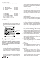
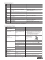
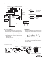
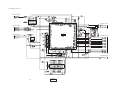
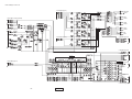
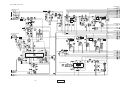
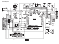
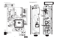
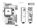
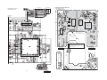
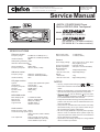
Clarion Co., Ltd.
50 Kamitoda, Toda-shi, Saitama 335-8511 Japan
Service Dept.: 5-66 Azuma , Kitamoto-shi, Saitama 364-0007 Japan
Tel: +81-48-541-2335 / 2432 FAX: +81-48-541-2703
Published by Service Dept.
298-6140-00 Dec.2003 P
Printed in Japan
Service Manual
AM/FM CD/MP3/WMA Player
Built-in DSP/EQ With Touchpanel
Model
(PE-2635B-A / For U.S.A.)
Model
(PE-2635K-A / For other countries)
(PE-2635K-B / For other countries)
SPECIFICATIONS
FM tuner section
Frequency range:
87.9MHz to 107.9MHz(U.S.A.)
87.0MHz to 108.0MHz(OTHERS)
Usable sensitivity:
9dBf
50dB quieting sensitivity: 15dBf
Alternate channel selectivity:
70dB
Stereo separation:
35dB (1kHz)
Frequency response:
30Hz to 15kHz (+/-3dB)
AM tuner section
Frequency range:
Usable sensitivity:
530kHz to 1710kHz(U.S.A.)
531kHz to 1629kHz(OTHERS)
25uV
CD player section
System:
Usable discs:
Frequency response:
S/N ratio:
Dynamic range:
Distortion:
+/-12dB (50Hz)
+/-12dB (12.5kHz)
General
Power supply voltage:
Current consumption:
Speaker impedance:
Dimensions(mm):
Source unit;
Remote control unit;
Weight:
Source unit;
Remote control unit;
14.4V DC(10.8V to 15.6V allowable) negative ground
Less than 15A,3A
4ohm(4ohm to 8ohm allowable)
178(W)x50(H)x155(D)
32(W)x56(H)x24(D)
1.7kg
80g(including battery)
NOTES
Compact disc digital audio system
Compact disc
5Hz to 20kHz (+/-1dB)
100dB (1kHz)
96dB (1kHz)
0.01%
MP3/WMA mode
MP3 sampling rate:
MP3 bit rate:
WMA bit rate:
Logical format:
Bass control action:
Treble control action:
11.025kHz to 48kHz
8kbps to 320kbps/VBR
48kbps to 192kbps
ISO9660 level1,2
JOLIET or Romeo
Audio section
Maximum power output: 53Wx4
Continous average power output:
18Wx4, into 4ohm, 20Hz to 20kHz,
1%THD
Line output level:
4V/F 2ch+4V/R 2ch (CD 1kHz)
4V/NON-FADER 2ch (CD 1kHz)
0.5V/2-ZONE 2ch (CD 1kHz)
-1-
* Use only compact discs bearing the
or
mark.
* Some CDs recorded in CD-R/CD-RW mode may not be
usable.
* WMA is the abbreviation of Windows Media Audio, an
audio file format developed by Microsoft Corporation.
, and the Windows logo are trade*
marks, or registerd trademarks of Microsoft Corporation
in the United States and/or other countries.
* This product includes technology owned by Microsoft Corporation and cannot be used or distributed without a license from MSLGP.
* This product is manufactured under license from Dolby
Laboratories."Dolby","Pro Logic" and the double-D symbol are trademarks of Dolby Laboratories.
* We cannot supply PWB with component parts in principle.
When a circuit on PWB has failure, please repair it by
component parts base. Parts which are not mentioned in
service manual are not supplied.
* Specifications and design are subject to change without
notice for further improvement.
DXZ945MP
DXZ946MP
COMPONENTS
PE-2635B-A,PE-2635K-A,PE-2635K-B
1.
2.
3.
4.
5.
6.
7.
8.
9.
10.
10-1.
10-2.
10-3.
Main unit
Rmote controller
Battery(SUM-3)
Mounting bracket
Universal MTG-bracket
DCP case
Outer escutcheon(*B-A)
Outer escutcheon(*K-A/B)
Extension lead
Parts bag
Removal key
Screw(M5x8)
Pad screw(M1.7x6)(*B-A)
----------RCB-164-600
----------300-4976-00
300-7742-00
335-5734-30
370-6089-00
370-6089-01
854-6349-50
----------331-2497-00
716-0496-01
716-0872-11
1
1
2
1
1
1
1
1
1
2
1
1
*B-A: For DXZ945MP (PE-2635B-A)
*K-A/B: For DXZ946MP (PE-2635K-A/B)
CAUTIONS
Use of controls, adjustment or performance of procedures
other than those specified herein, may result in hazardous
radiation exposure.
The COMPACT DISC player should not be adjusted or repaired by anyone except properly qualified service personnel.
Bottom view
of DXZ945MP
To engineers in charge of repair or
inspection of our products.
Before repair or inspection, make sure to follow the
instructions so that customers and Engineers in
charge of repair or inspection can avoid suffering
any risk or injury.
1. Use specified parts.
The system uses parts with special safety features against
fire and voltage. Use only parts with equivalent characteristics when replacing them.
The use of unspecified parts shall be regarded as remodeling for which we shall not be liable. The onus of product
liability (PL) shall not be our responsibility in cases where
an accident or failure is as a result of unspecified parts
being used.
2. Place the parts and wiring back in their original positions
after replacement or re-wiring.
For proper circuit construction, use of insulation tubes,
bonding, gaps to PWB, etc, is involved. The wiring conDXZ945MP
DXZ946MP
nection and routing to the PWB are specially planned using
clamps to keep away from heated and high voltage parts.
Ensure that they are placed back in their original positions
after repair or inspection.
If extended damage is caused due to negligence during
repair, the legal responsibility shall be with the repairing
company.
3. Check for safety after repair.
Check that the screws, parts and wires are put back securely in their original position after repair. Ensure for safety
reasons there is no possibility of secondary ploblems
around the repaired spots.
If extended damage is caused due to negligence of repair,
the legal responsibility shall be with the repairing company.
4. Caution in removal and making wiring connection to the
parts for the automobile.
Disconnect the battery terminal after turning the ignition
key off. If wrong wiring connections are made with the
battery connected, a short circuit and/or fire may occur. If
extensive damage is caused due to negligence of repair,
the legal responsibility shall be with the repairing company.
5. Cautions regarding chips.
Do not reuse removed chips even when no abnormality is
observed in their appearance. Always replace them with
new ones. (The chip parts include resistors, capacitors,
diodes, transistors, etc). The negative pole of tantalum
capacitors is highly susceptible to heat, so use special care
when replacing them and check the operation afterwards.
6. Cautions in handling flexible PWB
Before working with a soldering iron, make sure that the
iron tip temperature is around 270 . Take care not to apply the iron tip repeatedly(more than three times)to the
same patterns. Also take care not to apply the tip with force.
7. Turn the unit OFF during disassembly and parts replacement. Recheck all work before you apply power to the unit.
8. Cautions in checking that the optical pickup lights up.
The laser is focused on the disc reflection surface through
the lens of the optical pickup. When checking that the laser optical diode lights up, keep your eyes more than 30cms
away from the lens. Prolonged viewing of the laser within
30cms may damage your eyesight.
9. Cautions in handling the optical pickup
The laser diode of the optical pickup can be damaged by
electrostatic charge caused by your clothes and body. Make
sure to avoid electrostatic charges on your clothes or body,
or discharge static electricity before handling the optical
pickup.
9-1. Laser diode
The laser diode terminals are shorted for transportation in order to prevent electrostatic damage. After
replacement, open the shorted circuit. When removing the pickup from the mechanism, short the terminals by soldering them to prevent this damage.
9-2. Actuator
The actuator has a powerful magnetic circuit. If a
magnetic material is put close to it. Its characteristics will change. Ensure that no foreign substances
enter through the ventilation slots in the cover.
9-3. Cleaning the lens
Dust on the optical lens affects performance. To
clean the lens, apply a small amount of isopropyl
alcohol to lens paper and wipe the lens gently.
-2-
ERROR DISPLAYS
CD changer
DVD changer
Measure
Cause
A DISC is caught inside the CD deck and is not ejected.
This is a failure of CD deck's mechanism.
ERROR 3
A DISC cannot be played due to scratches,etc.
Replace with a non-scratched,non-warped-disc.
ERROR 6
A DISC is loaded upside-down inside the CD deck and does not
play.
Eject the disc then reload it properly.
AMP GUARD
The speaker protection circuit is operating.During this operation,
if any volume operation is performed, the display shows
"AMP GUARD".
"AMP GUARD" sometimes functions when special test signals are
used.
Turn down sound volume. Function can also be restored by
turning the power off and on again.
(Speaker volume is reduced automatically when the speaker
protection circuit operates).
ERROR 2
A DISC inside the CD changer is not loaded.
This is a failure of CD changer's mechanism.
ERROR 3
A DISC inside the CD changer cannot be played due to scratches,
etc.
Replace with a non-scratched, non-warped disc.
ERROR 6
A DISC inside the CD changer cannot be played because it is
loaded upside-down.
Eject the disc then reload it properly.
ERROR 2
A DISC inside the DVD changer cannot be played.
This is a failure of DVD mechanism.
ERROR 3
A DISC cannot be played due to scratches,etc.
Retry or replace with a non-scratched, non-warped-disc.
ERROR 6
A DISC inside the DVD changer cannot be played because it is
loaded upside-down.
Eject the disc then reload it properly.
ERROR P
Parental level error
Set the correct Parental level.
ERROR R
Region code error
Eject the disc and replace correct region code disc.
General
CD/MP3/WMA
Error Display
ERROR 2
*When an optional CD/DVD changer is connected through the CeNET cable, this unit can control CD/DVD changer operations.
*If an error display other than the ones described above appears, press the reset button.
TROUBLESHOOTING
Problem
Power does not turn on.
(No sound is produced.)
Measure
Cause
Fuse is blown.
Replace with a fuse of the same amperage.
Wire properly.
Power antenna lead is shorted to
ground or excessive current is required
for remote-on the amplifiers or power
antenna.
1. Turn the unit off.
2. Remove all wires attached to the power antenna lead. Check
each wire for a possible short to ground using an ohm meter.
3. Turn the unit back on.
4. Reconnect each amplifier remote wire to the turn off before
power antenna lead one by one. If the amplifiers
all wires are attached, use an external relay to provide
remote-on voltage(excessive current required).
Nothing happens when buttons
are pressed.
Display is not accurate.
The microprocessor has malfunctioned
due to noise,etc.
Turn of f the power , then
press the [ RELEASE ]
button and remove the DCP.
Press the reset button with
a thin rod.
DCP or main unit connectors are dirty.
Wipe the dirt off with a soft cloth moistened with cleaning alcohol.
There is a disc other than a compact
disc or foreign matter already in place.
With the slooping console open, press and hold the [ ] button
for 3 seconds or longer.The foreign matter is forcibly ejected.
MP3/WMA files are absent in a disc.
Write MP3/WMA files onto the disc properly.
Files are not recognized as an
MP3/WMA file.
Use MP3/WMA files encoded properly.
File system is not correct.
Use ISO9660 level 1, 2 or JOLIET or Romeo file system.
Disc is dirty.
Clean the disc with a soft cloth.
Disc is heavily scratched or warped.
Replace with a disc with no scratches.
Sound is cut or skipped.
Noise is generated or noise is
mixed with sound.
MP3/WMA files are not encoded properly.
Use MP3/WMA files encoded properly.
Sound is bad directly after power
is turned on.
Water droplets may form on the
internal lens when the car is parked in a
humid place.
Let dry for about 1 hour with the power on.
Wrong filename
File system is not correct.
Use ISO9660 level 1, 2 or JOLIET or Romeo file system.
Play list play is not performed.
File name or extension is not correct.
Use alphanumeric/ASCII characters for MP3/WMA file name.
Use ".M3U" for the file extension of a play list.
General
Incorrect wiring.
No sound output when operating
the unit with amplifiers or power
antenna attached.
CD/MP3/WMA
CD/MP3/WMA
No sound heard.
Sound skips or is noisy.
-3-
Reset button
DXZ945MP
DXZ946MP
DXZ945MP
DXZ946MP
-4-
IC770
DISPLAY
CONTROLLER
(LCD DRIVER)
IC701
DRIVER
IC302
ISOLATION
IE-BUS
DRIVER
IC602
IC740
TOUCH PANEL
U-COM
ACC 8V
STB
Q201
Q602
IC1
Q9
Q6
KEY
MATRIX
IC702
Q7
BL1
IC700
DCP U-COM
IC705
CONTRAST
Q700
IR
RECEIV.
IR700
IC301
Q701
VR700
ROTARY
Q703
IC501
IC606
MASTER
IC604
IC401
IE-BUS DRIVER
IC605
VOL
DET
DIMM
SW
Q710
IC508
IC509
IC507
Q711
BLINKING
LED
IC762
DCP
CD
MECH
CD MECH
MODULE
AUX IN
Ce-NET
ANT
AUDIO
Q201
Q210
Q227
8V STB
Q235
Q230
IC221
DSP 3.3V
IC220
6V STB
IC451
IC452
T201
IC101
IC201
Q603
Q212
Q213
Q229
Q231
Q226
KEY ILL
LCD BACK LIGHT
MOTOR
DRIVER
IC230
ILL SW
ILL DET
AUDIO
Q222,Q223
RCA
2-ZONE
Q456
Q457
PHONE
INT
ILL
POWER
ANT
AMP
REM
MECH 8V
STB
ACC
B/U
SP OUT
RCA NON
FADER
RCA
REAR
Q450
Q452
Q454
Q455
RCA
FRONT
Q451
Q453
BLOCK DIAGRAM
Main section
SLOPE
MOTOR
CD mechanism section
MP3&WMA Encoded disc/CD-DA disc
(CD-ROM ISO9660)
3.3V(I/O)
CD Mecha.
㵘㵘GS-1
1.6V(Core)
3.3V
IC4
LOGIC
SN74䌌䌖C139
P/U㵘CP-51
J2㵘10pin
IC6
DSP
TMS320DA140
(CD-ROM I/F)
(ECC)
(MPEG audio decode)
J1㵘15pin
IC101
DRIVER
FAN8047G3
IC102
CD㵘DSP
TC94A15F
(Digital servo)
(DF/DAC)
IC2
Regulator
3.3V㸢1.6V
IC7
LOGIC
SN74䌌䌖74
(WMA decode)
(CD-DA ESP)
3.3V
Q1
Transistor
5V㸢3.3V
IC9
DRAM
K4S641632F-TC60
(1M x 16bit x 4B)
3.3V
IC1
LOGIC
SN74䌌䌖C139
DAC
IC10
FLASH ROM
MBM29DL800BA
(8Mbit)
I/F-5V
V-BUS
AUDIO
D-OUT
IC3
LOGIC
SN74HCT08
ACC8V
J3 20pin (TO MAIN UNIT)
ACC5V
CODEMATIC
SYSTEM CHECK
This function prevents persons who do not know the touch
sequence from easily operating this unit. The Touch Code
display appears when DCP is attached and the power is
turned ON with "CODEMATIC" set to "ON".
The first time that this unit is turned on after wire connections are completed, this unit checks which equipment is
connected. (This is called the "system check.") When the
power is turned ON, and "System Check" is displayed, follow the procedure below to perform the system check.
1. When "System Check" appears on the display, press the
[ROTARY] knob.
The system check starts.
When the system check is complete,"Completed" appears on the display.
2. Press the [ROTARY] knob again.
The main display for the radio mode appears.
If you touch the display in this screen in the preset order,
"SUCCESSFUL" is displayed and the power is turned OFF.
When the power is next turned ON, the Touch Code display
does not appear, and the main display in the radio mode or
CD mode is displayed.
CONNECTIONS
16PIN SOCKET
(Power supply)
2-ZONE OUTPUT
(For wireless headphone)
GRN
AUX INPUT
8 MM
MA X
RCA 4CH OUTPUT
(For power amp)
EXTENSION LEAD
1
GRY
BLK
RED
RCA 2CH OUTPUT
(For center SP)
PUR
ANTENNA RECEPT.
(For radio antenna)
Ce NET
(For CD/DVD auto changer,TV)
* For details of connections, see "PRINTED
WIRING BOARD"(cf.page 31).
-5-
DXZ945MP
DXZ946MP
CIRCUIT DIAGRAM
Main PWB(B1) section 1/6
To Main PWB 5/6
(page 28)
5
To Main PWB 2/6
(page 25)
FM/AM Tuner
5
2
2
5
2
5
2
Selector
5
5
5
6
6
6
To Main PWB 6/6
(page 29)
To Main PWB 2/6
(page 25)
2
2
2
To Main PWB 2/6
(page 25)
2
2
AM+B
FM+B
2
To Main PWB 3/6
(page 26)
To Main PWB 6/6
(page 29)
3
6
3
6
6
To Main PWB 5/6
(page 28)
5
PLL
To Main PWB 2/6
(page 25)
2
SPE-ANA
2
2
6
To Main PWB 2/6
(page 25)
2
2
2
2
2
5
To Main PWB 5/6
(page 28)
- 24 -
DXZ945MP
DXZ946MP
To Main PWB 6/6
(page 29)
To Main PWB 2/6
(page 25)
Main PWB(B1) section 2/6
Inner escutcheon FPC(B4) section
To Main PWB 6/6
(page 29)
6
To Main PWB 1/6
(page 24)
1
1
IE-BUS Driver
1
13P DIN
(Ce NET)
1
To Main PWB 5/6
(page 28)
1
1
5
To Main PWB 6/6
(page 24)
1
1
1
To Main PWB 3/6
(page 26)
1
3
To Main PWB 5/6
(page 28)
3
3
5
3
PHONE-INT
5
3
To Main PWB 6/6
(page 29)
3
6
A
6
To J3 of CD PWB
(page 35)
To Main PWB 5/6
(page 28)
5
5
5
5
5
5
5
5
5
ILL-DET
Master Micro Computer
1
1
M30622MEP-126GP
1
To Main PWB 1/6 (page 24)
To Main PWB 4/6 (page 27)
4
4
1
1
1
1
1
To Main PWB 1/6 (page 24)
To Main PWB 6/6
(page 29)
5
6
B/U ACC-DET
6
6
6
Reset
6
To J701 of SW PWB
(page 32)
6
6
BLINKING-LED
DISC-IND
B
5
To Main PWB 5/6 (page 28)
For USA
(PE2635BA)
For Others
(PE2635KA,KB)
6
6
R688 10K
6
6
6
6
INNER ES FPC(B4)
SOCKET J800
To Main PWB 6/6
(page 29)
6
6
To Main PWB 6/6
(page 29)
- 25 -
DXZ945MP
DXZ946MP
Main PWB(B1) section 3/6
To Main PWB 2/6(page 25)
2
2
To Main PWB 1/6(page 24)
1
To Main PWB 2/6(page 25)
1
2
2
2
2
ADC/DSP/DAC
To Main PWB 6/6(page 29)
6
To Main PWB 4/6(page 27)
4
6
4
4
4
4
4
4
4
4
4
4
4
To Main PWB 5/6(page 28)
5
- 26 -
DXZ945MP
DXZ946MP
Main PWB(B1) section 4/6
To Main PWB 3/6
(page 26)
3
3
To Main PWB 5/6
(page 28)
5
To Main PWB 3/6
(page 26)
5
3
3
3
3
5
E-VOL
5
5
5
5
To Main PWB 3/6
(page 26)
3
3
3
3
To Main PWB 3/6
(page 26)
3
3
To Main PWB 6/6
(page 29)
6
6
To Main PWB 2/6
(page 25)
2
2
- 27 -
DXZ945MP
DXZ946MP
Main PWB(B1) section 5/6
To Main PWB 4/6(page 27)
NON FADER
OUTPUT
4
4
4
4
4
REAR
OUTPUT
4
To Main PWB 1/6,3/6,4/6(page 24,26,27)
1
3
4
FRONT
OUTPUT
To Main PWB 6/6(page 29)
6
6
6
2-ZONE
OUTPUT
To Main PWB 2/6(page 25)
2
AUX
INPUT
2
To Main PWB 1/6(page 24)
To Main PWB 1/6(page 24)
1
2
1
1
1
1
1
2
2
To Main PWB 6/6(page 29)
6
6
To Main PWB 2/6(page 25)
2
DISP
2
53Wx4 AMP
2
2
2
16P SOCKET
To Main PWB 2/6(page 25)
I
A
J
B
K
C
L
D
M
E
N
F
O
G
P
H
2
2
To Main PWB 1/6(page 24)
1
1
To Main PWB 2/6
(page 25)
2
2
6
6
6
To Main PWB 6/6(page 29)
- 28 -
DXZ945MP
DXZ946MP
Main PWB(B1) section 6/6
To Main PWB 1/6 (page 24)
1
To Main PWB 2/6 (page 25)
2
To Main PWB 1/6,4/6,5/6
(page 24,27,28)
2
Audio 8V
1
2
5
2
5
5
4
4
5
5
AMP
REM
6V STB
A-ANT
To Main PWB 5/6 (page 28)
5
-8V
To Main PWB 5/6
(page 28)
To Main PWB 2/6 (page 25)
2
2
20V
To Main PWB 5/6 (page 28)
5
5
5
To Main PWB 1/6,2/6,3/6
(page 24,25,26)
To Main PWB 2/6 (page 25)
2
1
2
2
5V
LCD +B
3
2
KEY ILL
SW
DISP 5V
2
8V STB
DISP 3.3V
To Main PWB 2/6 (page 25)
2
2
To Main PWB 3/6 (page 26)
3
To Main PWB 2/6 (page 25)
2
2
2
Slope motor ass'y
Motor driver
2
2
To Main PWB 2/6
(page 25)
1
To Main PWB 1/6
(page 24)
- 29 -
DXZ945MP
DXZ946MP
Main PWB(B1) section
Inner escutcheon FPC(B4) section
RCA 6CH cord
(855-5424-50)
RCA 4CH cord
(855-5493-50)
RED
RED
FRONT R-CH
GRY
13P DIN
(Ce NET)
2 13
O N M L
H
G F
K J
4
E D C B A
10
9
8 7
12
3
N.C
N.C
BUS(+)
11
13
RED
12
WHT
J
B
1
I
A
24
1
13
2Z-R
2Z-L
K
C
ANT Recept
23
AUX-L
M L
E D
WHT
11
AUX-R
N
F
NON FADER
R-CH
NON FADER
L-CH
1
NFL
NFR
O
G
2ZONE
R-CH
2ZONE
L-CH
WHT
PUR
ILLUMI
N.C
6 5 4 3
10 9 8 7
P
H
RED
GRN
REAR L-CH
R-CH(+)
2
WHT
REAR R-CH
BLK
I.REAR L-CH(-)(GRN/BLK)
A.REAR L-CH(+)(GRN)
1
12
25
13
14
24
C.FRONT L-CH(+)(WHT)
J.PHONE INT(BRN)
B.FRONT L-CH(-)(WHT/BLK)
D.FRONT R-CH(+)(GRY)
L.AUTO ANT(BLU)
M.REMOTE(BLU/WHT)
N.ILLUMI(ORG/WHT)
E.FRONT R-CH(-)(GRY/BLK)
F.REAR R-CH(+)(PUR)
G.REAR R-CH(-)(PUR/BLK)
FUSE(3A) 120-0030-00
56
15
43
28
1
24
1
29
42
100
76 75
1
2
1
25
51
50
1
16
26
1
28
75
51
K J
14
50
15
1
9
O N M L
A
16
P
F E D C B
I
100
26
1
25
Flat wire
(816-2643-50)
B
1
32
1
J800
18
Inner escutcheon
FPC(B4)
To J701 of SW PWB
(page 33)
Main PWB(B1)
COMPONENT SIDE
Slope motor ass'y
- 31 -
DXZ945MP
DXZ946MP
A
To J3 of CD PWB
(page 36)
20
17
8
Extension lead
(854-6349-50)
9
G
1
H
8
76
16
FUSE(15A) 120-0150-00
5
R-CH(-)
SYS-ACC
BUS(-)
L-CH(-)
GND
BACK UP 14V
L-CH(+)
1
6
I
FRONT L-CH
WHT
RED
12
P
FR
GRN
WHT/BLK
WHT
GRY
GRY/BLK
PUR
PUR/BLK
YEL
GRN/BLK
BRN
RED
BLU
BLU/WHT
ORG/WHT
YEL
BLK
RR
REAR L-CH(+)
FRONT L-CH(-)
FRONT L-CH(+)
FRONT R-CH(+)
FRONT R-CH(-)
REAR R-CH(+)
REAR R-CH(-)
BACK UP
REAR L-CH(-)
PHONE INT
ACC
AUTO ANT
REMOTE
ILLUMI
BACK UP(BUS)
GND
A
B
C
D
E
F
G
H
I
J
K
L
M
N
O
P
RL
FL
K.ACC(RED)
O.BACK UP(BUS)(YEL)
P.GND(BLK)
H.BACK UP(YEL)
16P Socket
AUX IN
R-CH
AUX IN
L-CH
RED
CIRCUIT DIAGRAM
Switch PWB(B2) section 1/2
CONTRAST ADJ:
CONTRAST ADJ:
ROTARY
VOL ADJ:5V or 0V
To SW PWB 2/2 (page 33)
2
2
2
To J800 of
Inner ES FPC
(page 25)
OTHER
CONTRAST ADJ:
2
CONTRAST ADJ:
B
2
2
To J772 of LCD PWB
(page 34)
C
(DIMMER:PLUS)
DCP Micro Computer
KEY ILL
0.6V(LIGHT)
MBM29F016A-90PFTN
ACC OFF:0V
OTHER:5.0V
- 32 -
DXZ945MP
DXZ946MP
4.9V(DARK)
PRINTED WIRING BOARD
Switch PWB(B2) section 2/2
Caution:
COMPONENT SIDE: Parts on the component side seen
from the component side are indicated.
Switch PWB(B2) section
SOLDER SIDE: Parts on the solder side seen from the
solder side are indicated.
2
2
2
2
2
2
1
To SW PWB
1/2(page 32)
To J800 of
Inner ES FPC
(page 31)
To J772 of
LCD PWB
(page 34)
C
Flat wire
(816-2641-50)
25
(Tuch panel SW-ON:PULS)
1
16
B
25
1
100
26
Touch Panel
Micro Computer
50
76
51
75
(Touch panel SW-ON:PULS)
24
To SW ass'y
(Touch panel)
4
25
48
1
D
1
(SW-ON:PULS)
48
37
1
To SW ass'y
(Touch panel)
D
36
25
12
13
24
(Tuch panel SW-ON:PULS)
(Tuch panel SW-ON:PULS)
(Tuch panel SW-ON:PULS)
(Tuch panel SW-ON:PULS)
- 33 -
DXZ945MP
DXZ946MP
Switch PWB(B2)
Switch PWB(B2)
COMPONENT SIDE
SOLDER SIDE
PRINTED WIRING BOARD
CIRCUIT DIAGRAM
LCD PWB(B3) section
Caution:
COMPONENT SIDE: Parts on the component side seen
from the component side are indicated.
C
SOLDER SIDE: Parts on the solder side seen from the
solder side are indicated.
CONTRAST ADJ:
CONTRAST ADJ:
25
28
15
1
14
1
100
26
50
76
51
75
1
LCD Controller
To J702 of Switch PWB
(page 33)
1
25
C
To LCD
E
To LCD
LCD Back Light on:
30
E
1
35
F
CONTRAST ADJ:
CONTRAST ADJ:
LCD PWB(B3)
F
COMPONENT SIDE
To LCD
To J702 of
SW PWB
(page 32)
LCD PWB(B3) section
- 34 -
DXZ945MP
DXZ946MP
LCD PWB(B3)
SOLDER SIDE
CIRCUIT DIAGRAM
CD PWB(B5) section 1/2
To CD PWB 2/2
(page 36)
To CD PWB1/2
(page 36)
A
To CD PWB 2/2
(page 36)
To J603 of Main PWB(page 25)
- 35 -
DXZ945MP
DXZ946MP
LED PWB-A(B6)
CD PWB(B5) section 2/2
LED PWB(B6) section
LED PWB-B(B6)
PRINTED WIRING BOARD
CD PWB(B5) section
LED PWB(B6) section
G
Spindle motor ass'y
M
Power motor ass'y
M
To CD PWB 1/2
(page 35)
H
G
Flat wire(816-2624-50)
Pick up ass'y
A
To J603 of Main PWB
(page 31)
Caution:
COMPONENT SIDE: Parts on the component side seen
from the component side are indicated.
SOLDER SIDE: Parts on the solder side seen from the
solder side are indicated.
SOLDER SIDE
CD PWB(B5)
Power motor ass'y
COMPONENT SIDE
H
G
LED PWB-B(B6)
To pick up ass'y
- 36 -
LED PWB-A(B6)
DXZ945MP
DXZ946MP
Spindle motor ass'y
CD PWB(B5)