1
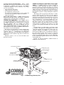
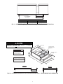
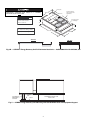
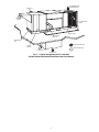
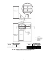
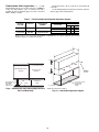
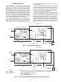
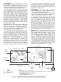
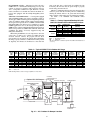
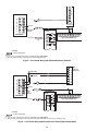
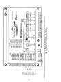
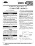
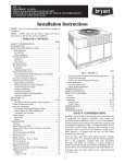
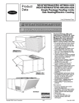
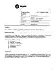
COBRA™ Energy Recovery Units
48/50HJ004-014 with 62AQ060-300
Single-Package Rooftop Units
and Field-Installed 62AQ060-300
ENERGY$RECYCLER™ Units
Application Data
CONTENTS
Page
GENERAL . . . . . . . . . . . . . . . . . . . . . . . . . . . . . . . . . . . . . 1-10
Features/Benefits . . . . . . . . . . . . . . . . . . . . . . . . . . . . . . . . 1
COBRA Curb Application . . . . . . . . . . . . . . . . . . . . . . . . 2
COBRA Iso-Exhaust Split Return Duct
Application . . . . . . . . . . . . . . . . . . . . . . . . . . . . . . . . . . . . 2
Field-Installed 62AQ Application . . . . . . . . . . . . . . . . 10
SYSTEM OPERATION . . . . . . . . . . . . . . . . . . . . . . . . 11-20
Cooling Mode . . . . . . . . . . . . . . . . . . . . . . . . . . . . . . . . . . . 12
Heating Mode . . . . . . . . . . . . . . . . . . . . . . . . . . . . . . . . . . . 12
Defrost . . . . . . . . . . . . . . . . . . . . . . . . . . . . . . . . . . . . . . . . . . 12
Changeover Thermostats . . . . . . . . . . . . . . . . . . . . . . . 15
Fans . . . . . . . . . . . . . . . . . . . . . . . . . . . . . . . . . . . . . . . . . . . . 16
COBRA and 62AQ Unit Options . . . . . . . . . . . . . . . . . 17
CONTROLS . . . . . . . . . . . . . . . . . . . . . . . . . . . . . . . . . . 21-28
Thermidistat™ Device. . . . . . . . . . . . . . . . . . . . . . . . . . . 21
PremierLink™ Controller . . . . . . . . . . . . . . . . . . . . . . . . 21
Gas Supply. . . . . . . . . . . . . . . . . . . . . . . . . . . . . . . . . . . . . . 28
WIRING . . . . . . . . . . . . . . . . . . . . . . . . . . . . . . . . . . . . . . 29-33
Field Power Supply. . . . . . . . . . . . . . . . . . . . . . . . . . . . . . 29
Factory-Supplied Non-Fused Disconnect . . . . . . . 29
Field Control Wiring . . . . . . . . . . . . . . . . . . . . . . . . . . . . . 29
CONDENSATE PIPING . . . . . . . . . . . . . . . . . . . . . . . . . . 34
DAMPERS. . . . . . . . . . . . . . . . . . . . . . . . . . . . . . . . . . . . . . . 34
Supply-Air Dampers. . . . . . . . . . . . . . . . . . . . . . . . . . . . . 34
Barometric Relief Damper . . . . . . . . . . . . . . . . . . . . . . . 34
Multiple Stage Cooling Control . . . . . . . . . . . . . . . . . . 34
DESIGN EXAMPLES. . . . . . . . . . . . . . . . . . . . . . . . . . .35,36
Design Example 1 . . . . . . . . . . . . . . . . . . . . . . . . . . . . . . . 35
Design Example 2 . . . . . . . . . . . . . . . . . . . . . . . . . . . . . . . 36
SELECTION PROCEDURE WITH
PACKAGED ROOFTOP BUILDER . . . . . . . . . . . .37,38
GENERAL
Carrier’s COBRA™ energy recovery units and fieldinstalled 62AQ Energy$Recycler™ units use Carrier’s patented
heat pump technology to reclaim energy from building exhaust
air. This energy is then used to pre-condition ventilation air for
the rooftop unit during winter and summer operation. These
units are designed to satisfy higher ventilation requirements and
other building codes while minimizing energy costs.
The 62AQ Energy$Recycler unit can be field-installed or
factory-installed. When it is factory-installed on a 48HJ or
50HJ rooftop unit, the combined total package is designated as
a COBRA unit. Factory installation of the 62AQ unit provides
the benefit of reduced field-installation time, single point
power connections, and the assurance of a factory test for the
complete COBRA unit. The COBRA unit requires less maintenance than other energy recovery systems and can be serviced
by a qualified refrigerant technician. See Fig. 1.
NOTE: The COBRA unit nameplate is located on the opposite
end of the rooftop section, on the upper right-hand part of the
panel due to the location of the 62AQ Energy$Recycler
section.
For field-installed 62AQ applications, the 62AQ unit must
be connected to the base unit in the field. The 62AQ unit
attaches directly to the return air opening of the rooftop unit
using hardware provided in an accessory mounting kit and
support rail. Power and control wiring for the 62AQ unit are
also field provided. The rooftop unit must be curb mounted in
the vertical supply and return configuration only. Connection to
competitive units requires field-supplied mounting arrangements and ductwork.
Additional literature available for 62AQ Energy$Recycler
units or the combined COBRA units include:
• The 62AQ Energy$Recycler Product Data: applies to
COBRA and field-installed 62AQ units.
• The COBRA Energy Recovery Unit Installation, StartUp and Service Supplement: applies to COBRA units
only.
• The 62AQ Energy$Recycler Installation, Start-Up and
Service Instructions applies to field-installed 62AQ
units.
Features/Benefits — Carrier’s COBRA and fieldinstalled 62AQ units provide all-in-one unitary offerings with
energy recovery capability and total latent load control.
DOWNSIZE ROOFTOP UNIT — By pre-conditioning the
outdoor air, the evaporator mixed entering air conditions can be
reduced, which may allow for use of a smaller tonnage rooftop
unit. Units have up to 100% outdoor air (OA) capability for
compliance with industry ventilation standards.
COST EFFICIENT OPERATION — Utilizing energy from
exhaust air allows for improved indoor air quality (IAQ) and
enhanced rooftop unit efficiency at both peak and part load
conditions.
ADDITIONAL STAGES — System flexibility allows for the
energy recovery device to operate as an additional stage of
heating or cooling.
EASE OF INSTALLATION — Available as a factoryinstalled option on the Weathermaster® 48/50HJ 3 to 121/2 ton
rooftop product line, COBRA energy recovery units provide
expanded capability to the rooftop unit’s performance. The
factory-installed COBRA energy recovery unit is applicable
for vertical-supply, vertical-return configuration units only.
UNIT MOUNTING — The 62AQ Energy$Recycler unit is
designed to mount directly to vertically ducted rooftop units
using an accessory mounting kit and support rail. No additional
roof curb is required.
Manufacturer reserves the right to discontinue, or change at any time, specifications or designs without notice and without incurring obligations.
Catalog No. 514-80013
Printed in U.S.A.
Form 48/50HJ,62AQ-2XA
Pg 1
12-05
Replaces: 48/50HJ,62AQ-1XA
Book 1 1
Tab 1a 1b
COBRA Iso-Exhaust, Split Return Duct Application — A COBRA application is capable of utilizing an
FACTORY INSTALLATION BENEFITS — When a 62AQ
Energy$Recycler™ unit is factory-installed on a rooftop unit, it
is designated as COBRA™ unit. See Fig. 1 for COBRA
configuration. Benefits of factory installation of the energy
recovery section include:
• reduced field-installation time
• single point power connections
• pre-configured iso-exhaust option
• less maintenance than other energy recovery systems and
serviceable by any qualified refrigeration technician
• single unit nameplate
ROOF CURB APPLICATIONS — COBRA and field-installed
62AQ units both require specific curb designs to support the
additional weight of the Energy$Recycler (E$R) unit.
“iso-exhaust” feature. Developed with indoor air quality in
mind, the iso-exhaust option allows the exhaust of poor quality
return air directly outside without contaminating supply air. In
addition, the energy from the previously unused exhaust air is
reclaimed and used to precondition the outdoor air, reducing
the load on the evaporator coil and providing better comfort for
occupants.
This design is ideal for applications where there is contaminated air (bathroom, photo processing, etc.) that cannot be
returned to the conditioned space and, therefore, MUST be
exhausted. A split-return-duct arrangement allows two separate
return ducts to be attached to the roof curb: “R2,” which contains “contaminated air,” is routed into the E$R section; “R1”
contains normal air that can be recirculated back to the space.
This design separates the two return airstreams so that the
exhaust air and the rooftop unit return air do not mix. Thus,
separate ducting is required for each stream of air, sized
according to the openings of the E$R section and rooftop unit
return.
The full perimeter roof curb featuring a “split-return” design
is available for this application. Although the position of the
“curb splitter bracket” that separates the return air into two
openings is adjustable, the COBRA “scoop” that directs the
return air into the E$R section is a fixed dimension. Therefore,
the “return support bracket” must be moved to appropriate
dimension for the applicable scoop, and the scoop must be
sealed (via provided seal-strip) to the roof curb. Additionally,
the R1 and R2 field-supplied ductwork must be mated and
sealed with the curb.
See Fig. 3A, 3B, 8A and 8B for additional details on
COBRA iso-exhaust dimensions.
COBRA Curb Application — The COBRA unit has
two proven mounting options. The preferred method is to use
the COBRA full-perimeter roof curb. See Fig. 2, 3A and 3B.
Two full perimeter curbs are available: part number
CRRFCURB022A00 is used with size 004-007 units, part
number CRRFCURB023A00 is used with size 008-014 units.
The full perimeter curb complies with NRCA (National Roofing Contractors Association) standards.
The unit may also be mounted on a Carrier standard rooftop
unit roof curb in combination with an accessory supplemental
equipment support or a field-fabricated and field-installed
support for the 62AQ section. The 62AQ section support is
required if the Carrier standard rooftop unit roof curb is used.
See Fig. 4-7.
Ductwork attaches to the roof curb. DO NOT attach
ductwork to the unit.
COBRA SUPPLY FAN
NON-FUSED DISCONNECT
COBRA SUPPLY COIL
COBRA OUTDOOR
AIR (OA) DAMPER
PREMIERLINK™
CONTROL OPTION
OUTDOOR
AIR
HIGH-STATIC FAN OPTION
EXHAUST
COBRA EXHAUST COIL
STAINLESS STEEL HEAT
EXCHANGERS OPTION
COBRA EXHAUST FAN
SUPPLY
AIR
Fig. 1 — COBRA Energy Recovery Unit
2
RETURN
AIR
FULL PERIMETER
ROOF CURB
UNIT
3 to 6 Ton
71/2 to 121/2 Ton
PART NUMBER
CRRFCURB022A00
CRRFCURB023A00
WEIGHT (lb)
135
162
Fig. 2 — COBRA™ Energy Recovery Unit Mounting with Full Perimeter Unit Roof Curb
DO NOT USE THIS DRAWING TO FIELD-FABRICATE A CURB!
SIGNIFICANT PROBLEMS CAN OCCUR IF A CARRIER
APPROVED CURB IS NOT USED.
Deck pans
2" Return support.
Only used on some
applications.
37 3/16"
67 3/8"
DUCT OPENING SIZES
3 1/4
R1
Supply = 13 7/8" x 20 1/4"
R1 = 13 5/8" x 17 3/4"
R2 = 13 5/8" x 12 5/16"
R2
14"
Deck pans must be
watertight
Supply
14"
R1 = Return from building to HVAC
2"
92 1/2"
R2 = Return from building to 62AQ
37 3/16"
SIDE VIEW
END VIEW
Fig. 3A — COBRA Energy Recovery Unit Full-Perimeter Roof Curb — 48/50HJ004-007 with 62AQ060, 100
3
Deck pans
DO NOT USE THIS DRAWING TO FIELD-FABRICATE A CURB!
SIGNIFICANT PROBLEMS CAN OCCUR IF A CARRIER
APPROVED CURB IS NOT USED.
2" Return support.
Only used on some
applications.
49 15/16"
78 1/4"
3 1/4
DUCT OPENING SIZES
R1
Supply = 15 11/16" x 31 3/8"
R1 = 15 5/16" x 29 1/16"
R2 = 15 5/16" x 9"
R2
14"
Deck pans must
be watertight
Supply
14"
2"
R1 = Return from building to HVAC
110 11/16"
R2 = Return from building to 62AQ
49 15/16"
SIDE VIEW
END VIEW
Fig. 3B — COBRA™ Energy Recovery Unit Full-Perimeter Roof Curb — 48/50HJ008-014 with 62AQ200, 300
ADJUSTABLE
EQUIPMENT
SUPPORT
RUBBER
PAD
STANDARD ROOFTOP UNIT
ROOF CURB
ROOF
Fig. 4 — COBRA Energy Recovery Unit Mounting with Standard Roof Curb and Equipment Support
4
CONNECTOR
PKG. ACCY.
B
C
D ALT
DRAIN
HOLE
CRBTMPWR001A01
CRBTMPWR002A01
CRBTMPWR003A01
CRBTMPWR004A01
GAS
3/ ″
4
[19]
NPT
1′-911/16″ 1′-4″
[551]
[406]
13/4″
[44.5]
1/ ″
2
[12.7]
NPT
3/ ″ [19]
4
NPT
POWER
3/
CONTROL
ACCESSORY
PWR
4″
[19]
NPT
1
1 /4″
[31.7]
3/ ″ [19]
4
NPT
11/4″
[31.7]
1/ ″
2
[12.7] NPT
1/ ″
2
[12.7] NPT
ROOF CURB
ACCESSORY
A
1′-2″
CRRFCURB001A01 [356]
2′-0″
CRRFCURB002A01 [610]
UNIT SIZE
004-007
NOTES:
1. Roof curb accessory is shipped disassembled.
2. Insulated panels.
3. Dimensions in [ ] are in millimeters.
4. Roof curb: galvanized steel.
5. Attach ductwork to curb (flanges of duct rest on
curb).
6. Service clearance: 4 ft on each side.
7.
Direction of airflow.
8. Connector packages CRBTMPWR001A01 and
2A01 are for thru-the-curb type gas. Packages
CRBTMPWR003A01 and 4A01 are for thru-thebottom type gas connections.
Fig. 5 — Roof Curb Details (48/50HJ004-007 Section Only)
5
CONNECTOR
PKG. ACCY.
B
C
D ALT
DRAIN
HOLE
CRBTMPWR001A01
CRBTMPWR002A01
CRBTMPWR003A01
CRBTMPWR004A01
GAS
3/ ″
4
[19]
NPT
2′-87/16″ 1′-1015/16″
[827]
[583]
13/4″
[44.5]
1/ ″
2
[12.7]
NPT
3/ ″ [19]
4
NPT
POWER
CONTROL
ACCESSORY
PWR
3/ ″
4
[19]
NPT
1
1 /4″
[31.7]
3/ ″ [19]
4
NPT
11/4″
[31.7]
1/ ″
2
[12.7] NPT
1/ ″
2
[12.7] NPT
ROOF CURB
ACCESSORY
A
1′-2″
CRRFCURB003A01 [356]
2′-0″
CRRFCURB004A01 [610]
UNIT SIZE
008-014
NOTES:
1. Roof curb accessory is shipped disassembled.
2. Insulated panels: 1-in. thick polyurethane foam,
13/4 lb density.
3. Dimensions in [ ] are in millimeters.
4. Roof curb: 16-gage steel.
5. Attach ductwork to curb (flanges of duct rest on
curb).
6. Service clearance 4 ft on each side.
7.
Direction of airflow.
8. Connector packages CRBTMPWR001A01 and
2A01 are for thru-the-curb gas type. Packages
CRBTMPWR003A01 and 4A01 are for thruthe-bottom type gas connections.
Fig. 6 — Roof Curb Details (48/50HJ008-014 Section Only)
6
CONDENSER-FAN
DISCHARGE AIR
EXHAUST
AIR
FRESH AIR
INLET
OUTDOOR-AIR
INLET
ROOF CURB
RETURN AIR
BAFFLE
MOUNTING
KIT
OUTDOOR AIRFLOW
FILTER
ACCESS
INDOOR AIRFLOW
SUPPLY AIR
RETURN AIR
Fig. 7 — Typical Energy$Recycler™ Installation
(Field-Installed 62AQ with Standard Unit Roof Curb Shown)
7
(W)
AA
(L)
R2
R1
62AQ060 or 100
LOCATION
10.3 in.
10.3 in.
(W)
A
B
(L)
LIP ON
SCOOP
EXTENDS
OVER THIS
AREA
62AQ060 or 100
LOCATION
SUPPLY
LEGEND
R1 — Airflow recirculated
through the 48/50HJ
rooftop unit
R2 — Airflow through the
62AQ unit
62AQ SIZE
060,100
COBRA SCOOP OPENING
FOR RETURN AIR (A)
L (in.)
W (in.)
10.3
10.1
48/50HJ
SIZE
004-007
ROOFTOP RETURN-AIR
DUCT OPENING DIMENSIONS
(B)
L (ft-in.)
W (ft-in.)
0-1015/16
2-111/16
Fig. 8A — COBRA™ Iso-Exhaust Return Air Hood Dimensions —
48/50HJ004-007 Units with 62AQ060, 100
8
(W)
(L)
A
R1
R2
62AQ200 or 300
LOCATION
18.9 in.
18.9 in.
(W)
B
A
62AQ200 or 300
LOCATION
(L)
LIP ON
SCOOP
EXTENDS
OVER THIS
AREA
SUPPLY
LEGEND
R1 — Airflow recirculated
through the 48/50HJ
rooftop unit
R2 — Airflow through the
62AQ unit
62AQ SIZE
200, 300
COBRA SCOOP OPENING
FOR RETURN AIR (A)
L (in.)
W (in.)
18.9
10.1
48/50HJ
SIZE
008
009-014
ROOFTOP RETURN-AIR
DUCT OPENING DIMENSIONS
(B)
L (ft-in.)
W (ft-in.)
1-05/8
2-911/16
3-03/8
1-05/8
Fig. 8B — COBRA™ Iso-Exhaust Return Air Hood Dimensions —
48/50HJ008-014 Units with 62AQ200, 300
9
Field-Installed 62AQ Application — A fieldinstalled 62AQ energy recovery unit cannot use a COBRA™
rooftop unit full perimeter curb. A standard curb with a
mounting kit and an adjustable support are used, as shown in
Table 1 and Fig. 9 and 10.
Ductwork attaches to the roof curb; do not attach ductwork
to the unit.
See the 62AQ installation instructions for details on mounting kits, support rails and installation.
Table 1 — Field-Installed 62AQ Required Equipment Support
ROOFTOP
UNIT SIZE
62AQ UNIT
MOUNTING KIT
NUMBER
3-6 Ton
060, 100
CRMTGKIT001A00
71/2 -121/2 Ton
200, 300
CRMTGKIT002A00
ADJUSTABLE EQUIPMENT SUPPORT RAIL
Dimensions (in.)
Part Number
A
B
C
CRAQSUPT001A00
36.9
40
8 to 14
CRAQSUPT002A00
36.9
40 14 to 24
CRAQSUPT003A00
49.7
54
8 to 14
CRAQSUPT004A00
49.7
54 14 to 24
NOTE: Pairing 3 to 6 ton rooftop units with 62AQ200 or 62AQ300 units is not a factory supported option. Contact
Application Engineer for additional information.
4”
A
FLUSH MOUNTING
ENERGY$RECYCLER™
SECTION
ADJUSTABLE
EQUIPMENT
SUPPORT
(SEE FIG.10)
PAD
ROOF
C”
ROOFTOP UNIT
SECTION
SCREW
SUPPORT
IN PLACE
UNIT ROOF
CURB
Fig. 9 — Rooftop Unit and Field-Installed 62AQ Unit
(NOT a COBRA Unit)
0.75” THICK
10” x B (SEE CHART)
PROTECTIVE
RUBBER PAD
(EPDM)
NOTE: See dimensions in Table 1.
Fig. 10 — Adjustable Equipment Support
10
SYSTEM OPERATION
net effect takes heat from the incoming outdoor air and rejects
it into the exhaust air.
In heating mode, the E$R lower coil acts as the evaporator,
which absorbs heat from the exhaust air before it is ejected into
atmosphere. The upper coil acts as the condenser, which adds
heat to the outdoor air before it enters the rooftop unit. The net
effect is to remove heat from the building exhaust air and use it
to warm the incoming outdoor ventilation air.
Additionally, the COBRA and field-installed 62AQ units
utilize an occupied/unoccupied strategy to maximize conditioning efficiency. In general, a maximum of three stages are
available for cooling: OA (if suitable for free cooling), the
62AQ Energy$Recycler unit and rooftop unit compressor 1,
and the rooftop unit circuit 2. However, the 62AQ Energy$Recycler unit utilizes the occupied/unoccupied schedule, room
temperature, humidity set points, and the OA thermostat set
points to determine what is necessary to properly condition
the air.
The COBRA™ and field-installed 62AQ Energy$Recycler™ units replace the rooftop unit economizer and
contain their own powered two-position outdoor air (OA)
damper. See Fig. 1. Outdoor air passes through the damper,
then through the upper coil and into the rooftop unit, where it
mixes with return air before entering the rooftop evaporator
coil. The exhaust portion of the rooftop unit return air is directed past the 62AQ Energy$Recycler (E$R) compressor, through
the lower coil and then out to the atmosphere. The E$R portion
of the unit is a heat pump that uses the preconditioned exhaust
air as a heat source/sink. Refer to Fig. 11-17 and Tables 2A and
2B for operating information and system response.
In cooling mode the E$R upper coil acts as the evaporator.
When needed, the E$R upper coil cools and dehumidifies the
outdoor air before it enters the rooftop unit. The lower coil acts
as the condenser, which is cooled by building exhaust air. The
ROOFTOP UNIT
ENERGY RECOVERY SECTION
MIXED AIR
CONDENSER
COMPRESSOR
R
EXHAUST AIR
EVAPORATOR
O
AT
R
O
AP
EV
OUTSIDE AIR
ROOF LINE
ROOM AIR
SUPPLY AIR
THERMIDISTAT/
HUMIDISTAT
Fig. 11 — Typical Unit Airflow Diagram
ROOFTOP UNIT
ENERGY RECOVERY SECTION
COMPRESSOR
CONDENSER
EXHAUST AIR
MIXED AIR
EVAPORATOR
R
O
AT
R
O
AP
EV
70 F db/
67 F wb
OUTSIDE AIR
ROOF LINE
ROOM AIR
85 F db/
75 F wb
db
RH
wb
LEGEND
— Dry Bulb
— Relative Humidity
— Wet Bulb
SUPPLY AIR
THERMIDISTAT/
HUMIDISTAT
NOTES:
1. If outdoor air quality is poor or outdoor air relative humidity is too high, only the rooftop unit compressor will be
on during cooling. The energy recovery section will not energize when outdoor air is unsuitable.
2. Space temperature unoccupied set point = 84 F
Space temperature = 85 F
Space relative humidity set point = 65% RH
Space relative humidity = 63% RH
Fig. 12 — Typical Unoccupied Cooling Operation (Unsuitable Outdoor Air)
11
Cooling Mode — The cooling changeover thermostat
located on the hood of COBRA™ and 62AQ energy recovery
units determines when the energy recovery unit goes into
economizer mode. When the outdoor temperature is below the
cooling set point, the unit will be in economizer mode.
In the unoccupied mode, fans are normally set for AUTO
operation, causing the fans to cycle on only as needed for heating or cooling. If the light commercial Thermidistat™ device is
set for “AUTO” fan, the rooftop unit fan will be off except
when cooling or humidity control is required. The energy
recovery unit fans will be off except when unit is running in the
economizer mode. If the light commercial Thermidistat device
is set to “ON” for fan, the energy recovery unit and rooftop unit
fans will run continuously. If outdoor air is below the outdoor
air thermostat set point, the compressors are locked off and the
unit operates in economizer mode when cooling is required. If
outdoor air is unsuitable due to humidity or quality, the energy
recovery unit turns off and only the rooftop unit compressor
runs when cooling is required.
NOTE: The energy recovery unit does not run and dampers are
closed when the outdoor air is unsuitable for cooling and the
mode is unoccupied. If outdoor air is suitable, first stage cooling is energy recovery unit in economizer mode and all compressors are off. Second stage cooling adds the energy recovery
unit compressor and rooftop unit compressor no. 1.
In occupied mode, when the energy recovery unit compressor runs in cooling mode, it is extracting heat from the incoming outdoor air and rejecting heat to the exhaust air. The energy
recovery unit and rooftop unit fans run continuously. On a first
stage call, all compressors will be off if the outdoor air is
suitable for free cooling. Otherwise, the energy recovery unit
compressor and rooftop unit compressor no. 1 will run
whenever there is a first stage demand for cooling. For units
with a 2-stage rooftop unit, the energy recovery unit compressor and the rooftop unit compressor no. 1 and 2 will run
whenever there is a demand for cooling on a second stage call.
Units with a single stage rooftop unit are not factory configured
for a second stage call. If there is a demand for humidity
control but not cooling, only the energy recovery unit
compressor will run. If there is a field-installed CO2 sensor and
the levels are below that sensor set point, then the unit will
operate in the unoccupied mode sequence (the energy recovery
unit dampers will be closed and rooftop unit operation
maintains space conditions only).
Heating Mode — The heating changeover thermostat
located on the energy recovery unit hood determines the stage
1 to stage 2 switchover point in heating mode.
In unoccupied mode, the energy recovery unit is off and all
compressors are locked off. First stage heat is rooftop unit heat
at 50%. Second stage heat is rooftop unit heat at 100%.
In unoccupied mode, when the energy recovery unit compressor runs in heat mode, it is extracting heat from the exhaust
air and rejecting heat to the incoming outdoor air; it is returning
energy to the building that would, otherwise, be “thrown
away.” The energy recovery unit and rooftop unit fans run continuously. The rooftop unit compressors are always off. On a
first stage call, the energy recovery unit compressor is on in
heat mode. Rooftop unit heat is off if the outdoor air is above
the set point. Rooftop unit heat is on at 50% if the outdoor air is
below the set point. On a second stage call, the energy recovery
unit compressor is on in heat mode. Rooftop unit heat is on a
50% if the outdoor air is above the set point. Rooftop unit heat
is on at 100% if the outdoor air is below the set point.
Defrost — If the temperature of the 62AQ section condenser (exhaust air) coil drops below 28 F at the defrost
thermostat (DFT) and the defrost timer is at the end of a timed
period (adjustable to 30, 50 or 90 minutes), then the reversing
valve solenoid (RVS) is energized and the condenser fan contactors are deenergized. This switches the position of the
reversing valve and shuts off the 62AQ section condenser
(exhaust air) fan. The unit continues to defrost until the coil
temperature measured at the DFT reaches 65 F or the defrost
cycle completes a 10-minute cycle. At the end of the defrost
cycle the RVS deenergizes and the exhaust fan motor energizes
to put the unit in heating mode. If the space thermostat is satisfied during a defrost cycle, then the 62AQ section will continue
in the Defrost mode until the defrost cycle is complete.
ROOFTOP UNIT
ENERGY RECOVERY SECTION
O
R
O
AT
MIXED AIR
CONDENSER
COMPRESSOR
R
EXHAUST AIR
EVAPORATOR
AP
EV
67 F db/
57 F wb
OUTSIDE AIR
ROOF LINE
ROOM AIR
85 F db/
72 F wb
db
RH
wb
LEGEND
— Dry Bulb
— Relative Humidity
— Wet Bulb
SUPPLY AIR
THERMIDISTAT/
HUMIDISTAT
NOTES:
1. First stage — Unit is in economizer mode.
2. Second stage — Both energy recovery section and rooftop unit section compressors are not running.
3. Space temperature unoccupied set point = 84 F
Space temperature = 85 F
Space relative humidity set point = 65% RH
Space relative humidity = 55% RH
Fig. 13 — Typical Unoccupied Cooling Operation (Suitable Outdoor Air)
12
ROOFTOP UNIT
ENERGY RECOVERY SECTION
O
R
O
AT
MIXED AIR
CONDENSER
COMPRESSOR
R
EXHAUST AIR
EVAPORATOR
AP
EV
95 F db/
78 F wb
OUTSIDE AIR
ROOF LINE
ROOM AIR
78 F db/
69 F wb
LEGEND
db — Dry Bulb
RH — Relative Humidity
wb — Wet Bulb
SUPPLY AIR
THERMIDISTAT/
HUMIDISTAT
NOTES:
1. Space temperature occupied set points
Stage 1 = 75 F
Stage 2 = 76.5 F
Space temperature = 78 F
Space relative humidity set point = 60% RH
Space relative humidity = 65% RH
2. Stage 1 Cooling = Energy Recovery section compressor ON, Rooftop Unit section compressor no. 1 ON.
Stage 2 Cooling = Energy Recovery section compressor ON, Rooftop Unit section compressors no. 1
and 2 ON. (2-Stage Rooftop units only)
Fig. 14 — Typical Occupied Cooling Operation (Space Temperature and Humidity Above Set Points)
ROOFTOP UNIT
ENERGY RECOVERY SECTION
O
R
O
AT
MIXED AIR
CONDENSER
COMPRESSOR
R
EXHAUST AIR
EVAPORATOR
AP
EV
95 F db/
78 F wb
OUTSIDE AIR
ROOF LINE
ROOM AIR
78 F db/
75 F wb
LEGEND
db — Dry Bulb
RH — Relative Humidity
wb — Wet Bulb
SUPPLY AIR
THERMIDISTAT/
HUMIDISTAT
NOTES:
1. Space temperature occupied set points
Stage 1 = 75 F
Stage 2 = 76.5 F
Space temperature = 78 F
Space relative humidity set point = 60% RH
Space relative humidity = 50% RH
2. Stage 1 Cooling = Energy Recovery section compressor ON, Rooftop Unit section compressor no. 1 ON.
Stage 2 Cooling = Energy Recovery section compressor ON, Rooftop Unit section compressors no. 1 and
2 ON. (2-Stage Rooftop units only)
Fig. 15 — Typical Occupied Cooling Operation
(Space Temperature Above Set Point and Space Humidity Below Set Point)
13
ROOFTOP UNIT
ENERGY RECOVERY SECTION
COMPRESSOR
CONDENSER
EXHAUST AIR
MIXED AIR
EVAPORATOR
R
O
AT
R
O
AP
EV
85 F db/
75 F wb
OUTSIDE AIR
ROOF LINE
ROOM AIR
74 F db/
65 F wb
LEGEND
db — Dry Bulb
RH — Relative Humidity
wb — Wet Bulb
SUPPLY AIR
THERMIDISTAT/
HUMIDISTAT
NOTES:
1. Space temperature occupied set points
Stage 1 = 75 F
Stage 2 = 76.5 F
Space temperature = 74 F
Space relative humidity set point = 60% RH
Space relative humidity = 66% RH
2. Energy recovery section will energize compressors to provide humidity relief. Rooftop unit compressors
will not energize.
Fig. 16 — Typical Occupied Cooling Operation
(Space Temperature Below Set Point and Space Humidity Above Set Point)
ROOFTOP UNIT
ENERGY RECOVERY SECTION
O
R
O
AT
MIXED AIR
CONDENSER
COMPRESSOR
R
EXHAUST AIR
EVAPORATOR
AP
EV
95 F db/
78 F wb
OUTSIDE AIR
ROOF LINE
ROOM AIR
72 F db/
60 F wb
db
IAQ
RH
wb
—
—
—
—
LEGEND
Dry Bulb
Indoor-Air Quality
Relative Humidity
Wet Bulb
SUPPLY AIR
THERMIDISTAT/
HUMIDISTAT
NOTES:
1. Space temperature occupied set points
Stage 1 = 75 F
Stage 2 = 76.5 F
Space temperature = 72 F
Space relative humidity set point = 60% RH
Space relative humidity = 50% RH
2. Unit will not bring on compressors. Energy recovery and rooftop supply fans will run to provide outdoor
air to satisfy IAQ ventilation demand.
Fig. 17 — Typical Occupied Cooling Operation
(Space Temperature and Humidity Below Set Points)
14
Table 2A — COBRA™ Energy Recovery Unit Sequence of Operation — Unoccupied
COOLING
Indoor Temperature Above Y2*
Humidity Low & OAT Low
Humidity Low & OAT High
Humidity High & OAT Low
Humidity High & OAT High
Indoor Temperature Between Y1 & Y2*
Humidity Low & OAT Low
Humidity Low & OAT High
Humidity High & OAT Low
Humidity High & OAT High
Indoor Temperature Below Y1
Humidity Low
Humidity High
NOTE: OAT < 55 F all compression off
HEATING
Indoor Temperature Above W1
Indoor Temperature Between W1 & W2
Indoor Temperature Below W2
E$R Compressor
UNOCCUPIED
E$R Fans
RTU Compressor 1
RTU Compressor 2*
RTU Fans
RTU Heat
On
Off
Off
Off
On (cyc.)
Off
Off
Off
On
On
On
On
Off
On
On
On
On (cyc.)
On (cyc.)
On (cyc.)
On (cyc.)
Off
Off
Off
Off
Off
Off
Off
Off
On (cyc.)
Off
Off
Off
Off
On
On
On
Off
Off
On
On
On (cyc.)
On (cyc.)
On (cyc.)
On (cyc.)
Off
Off
Off
Off
Off
Off
Off
Off
Off
On
Off
On
Off
On (cyc.)
Off
Off
E$R Compressor
E$R Fans
RTU Compressor 1
RTU Compressor 2*
RTU Fans
Off
Off
Off
Off
Off
Off
Off
Off
Off
Off
Off
Off
Off
On (cyc.)
On (cyc.)
LEGEND
E$R — Energy$Recycler™ Unit
OAT — Outdoor Air Temperature
RTU — Rooftop Unit
RTU
Heat†
Off
On, 50%
On, 100%
*Second stage for Y2 call applicable on rooftop units with 2 circuits only.
†50% rooftop unit heat only applicable with 2-stage electric or gas heating
units.
Table 2B — COBRA Energy Recovery Unit Sequence of Operation — Occupied
COOLING
Indoor Temperature Above Y2*
Humidity Low & OAT Low
Humidity Low & OAT High
Humidity High & OAT Low
Humidity High & OAT High
Indoor Temperature Between Y1 & Y2*
Humidity Low & OAT Low
Humidity Low & OAT High
Humidity High & OAT Low
Humidity High & OAT High
Indoor Temperature Below Y1
Humidity Low
Humidity High
NOTE: OAT < 55 F all compression off
HEATING
Indoor Temperature Above W1
Indoor Temperature Between W1 & W2
OAT >Set Pt (30 F)
OAT <Set Pt (30 F)
Indoor Temperature Below W2
OAT >Set Pt (30 F)
OAT <Set Pt (30 F)
E$R Compressor
OCCUPIED
E$R Fans
RTU Compressor 1
RTU Compressor 2*
RTU Fans
RTU Heat
On
On
On
On
On
On
On
On
On
On
On
On
Off
On
On
On
On
On
On
On
Off
Off
Off
Off
Off
On
On
On
On
On
On
On
Off
On
On
On
Off
Off
On
On
On
On
On
On
Off
Off
Off
Off
Off
On
On
On
Off
Off
Off
Off
On
On
Off
Off
E$R Compressor
Off
E$R Fans
On
RTU Compressor 1
Off
RTU Compressor 2
Off
RTU Fans
On
RTU Heat
Off
On
On
On
On
Off
Off
Off
Off
On
On
Off
On, 50%
On
On
On
On
Off
Off
Off
Off
On
On
On, 50%
On, 100%
LEGEND
E$R — Energy$Recycler Unit
OAT — Outdoor Air Temperature
RTU — Rooftop Unit
*Second stage for Y2 call applicable on rooftop units with 2 circuits only.
†50% rooftop unit heat only applicable with 2-stage electric or gas heating
units.
Changeover Thermostats — Changeover thermostats
are used to adjust the changeover set points for heating and
cooling. The thermostats must be relocated from the shipping
location to the operating location in the supply outdoor air
hood. See Fig. 18 for shipping arrangement.
COOLING — The cooling outdoor air changeover thermostat
set point determines when the energy recovery unit goes into
economizer mode (energy recovery compressor OFF, energy
recovery supply fan ON). It is adjustable from 45 F to 75 F, will
“make” as the temperature falls and will reset at 4º F differential above the set point.
For example, if the cooling changeover thermostat is set for
72 F, the unit is in unoccupied or occupied mode, the outdoorair temperature is 70 F, there is low space relative humidity,
and the unit cooling set point (Y1) is 75 F, then the first stage of
cooling is the 62AQ Energy$Recycler section economizer. The
second stage of cooling is the 62AQ Energy$Recycler section
and the rooftop unit compressor no. 1. The rooftop unit no. 2
compressor is locked out below 55 F.
HEATING CHANGEOVER
THERMOSTAT (RED LABEL)
COOLING CHANGEOVER
THERMOSTAT
Fig. 18 — Changeover Thermostat
Shipping Location
15
HEATING — The heating outdoor air changeover thermostat
determines the heating stage 1 to heating stage 2 switchover
point. During heating, the rooftop unit supply fan and energy
recovery unit supply fan are both always on. It is adjustable
from 5 F to 50 F, will “make” as the temperature falls and will
reset at 4º F differential above the set point.
As an example, if the switchover set point is 30 F and the
outdoor ambient temperature is above 30 F, then the first stage
of heating is the energy recovery unit. The second stage of
heating is the energy recovery unit and the first stage of heating
for the rooftop unit.
If the switchover set point is 30 F and the outdoor ambient
temperature is below 30 F, then the first stage of heating is the
62AQ Energy$Recycler™ unit and the first stage of heating
for the rooftop unit. The second stage of heating is the 62AQ
Energy$Recycler unit and the second stage of heating for the
rooftop unit.
NOTES:
1. On rooftop units with only single stage heat, set the heating changeover thermostat as low as possible for 2-stage
heat capability.
2. On units produced prior to December 2004, the labels for
the Heating thermostats may require replacement. The
correct label is shown in Fig. 19. See Service Managers
Bulletin (SMB) 04-0044 for obtaining a current outdoor
air thermostat for heating label.
MIN
0˚
MAX
20˚
50˚
40˚
o
10˚
30˚
OUTDOOR AIR THERMOSTAT
MOUNTING
1. MOUNT HEATING OUTDOOR AIR
THERMOSTAT (RED LABEL) WITH
QUICK CONNECTS TOWARD TOP.
2. SET DESIRED OUTDOOR AIR
TEMPERATURE BELOW WHICH
THE SECOND STAGE HEAT OF
THE MAIN UNIT IS ALLOWED
TO BE ENERGIZED.
Fig. 19 — Outdoor-Air Thermostat Heating Label
If the desired fan speed is not specified during the job selection, the proper settings for the E$R supply fan and damper and
exhaust fan and damper must be determined using the applicable fan tables, the desired outdoor air cfm and return static pressure. See applicable Supply Air Fan Kit Accessory Installation
Instructions for additional details on altering fan speeds.
Fans — There are two fans in the Energy$Recycler (E$R)
portion of the COBRA™ energy recovery unit or fieldinstalled 62AQ unit: the supply fan and exhaust fan. For applicable fan curves, see the 62AQ Energy$Recycler Installation,
Start-Up and Service Instructions or the 62AQ
Energy$Recycler Product Data manual.
16
COBRA™ and 62AQ Unit Options
COBRA/62AQ energy recovery units equipped with the
Humidi-MiZer dehumidification option.
Unoccupied mode with Humidi-MiZer (Table 3A) — In the
unoccupied mode, the Energy$Recycler (E$R) unit is off and
all compressors are locked off. First stage heat is rooftop unit
heat at 50%. Second stage heat is rooftop unit heat at 100%.
Occupied Mode with Humidi-MiZer (Table 3B) — In the occupied mode, when the E$R compressor runs in heat mode, it
extracts heat from the exhaust air and rejects heat to the incoming outdoor air, returning energy to the building that otherwise
would be wasted. The E$R and rooftop unit fans run continuously. Rooftop unit compressors are always off.
On a first stage call, the E$R compressor is on in heat mode.
If the outdoor air is above the set point, rooftop unit heat is off.
Rooftop unit heat is on at 50% if the outdoor air is below the
set point. On a second stage call, the E$R compressor is on in
heat mode. Rooftop unit heat is on at 50% if the outdoor air is
above the set point. Rooftop unit heat is on at 100% if the
outdoor air is below the set point.
NOTE: If there is a thermostat call from the space for heating,
all dehumidification (both subcooling mode and hot gas reheat
mode) will not operate.
HUMIDI-MIZER™ OPTION (Units after October 2004) —
Units equipped with the Humidi-MiZer dehumidification
option are capable of increased humidity control by utilizing a
common subcooling/reheat dehumidification coil. This unique
and innovative design provides the capability of the rooftop
unit to operate in both a subcooling mode and a hot gas reheat
(HGRH) mode. A 48/50HJ rooftop unit equipped with the
Humidi-MiZer system can be used with or without a 62AQ
Energy$Recycler™ unit. See Fig. 20 for the HGRH mode of
operation. See the Humidi-MiZer Application Data manual for
additional details.
The incorporation of the Humidi-MiZer adaptive dehumidification system on a COBRA unit or a rooftop unit with a
field-installed 62AQ unit adds significant flexibility to the
overall system. The response of the Humidi-MiZer system to
varying space conditions is extremely dynamic. The 48/50HJ
rooftop unit equipped with the Humidi-MiZer system, with or
without a COBRA energy recovery unit, will respond based on
the temperature and humidity requirements as sensed in the
space. Either a Carrier Thermidistat™ device (combined
temperature and humidity sensing capability) or separate thermostat and humidistat can be used with the Humidi-MiZer
system. Tables 3A and 3B outline the sequence of operation for
HGSV
(Hot Gas
Solenoid Valve)
Condenser
Coil
Evaporator
Coil
Discharge
Line
Compressor
(Crankcase
Heater)
Subcooling / Reheat
Dehumidification
Coil
ir
rA
o
tdo
Ou
id
e
Lin
u
Liq
Suction Line
CCH
(Crankcase
Heater)
(Equalizer
Line)
(Bulb)
LPS
(Low Pressure
Switch)
or
o
Ind
Air
TXV
(Thermostatic
Expansion
Valve)
Fig. 20 — Humidi-MiZer Dehumidification Option Schematic
(Hot Gas Reheat Mode of Operation)
17
LLSV
(Liquid Line
Solenoid Valve)
Table 3A — Humidi-MiZer™ Adaptive Dehumidification System Rooftop with COBRA™ Energy Recovery Unit
Sequence of Operation — Unoccupied
COOLING
Indoor Temperature Above Y2
Humidity Low & OAT Low
Humidity Low & OAT High
Humidity High & OAT Low
Humidity High & OAT High
Indoor Temperature Between Y1 & Y2
Humidity Low & OAT Low
Humidity Low & OAT High
Humidity High & OAT Low
Humidity High & OAT High
Indoor Temperature Below Y1
Humidity Low
Humidity High
NOTE: OAT < 55 F all compression off
HEATING
Indoor Temperature Above W1
Indoor Temperature Between W1 & W2
Indoor Temperature Below W2
LEGEND
E$R
— Energy$Recycler™ Unit
HGRH — Hot Gas Reheat
OAT
— Outdoor Air Temperature
E$R Compressor
UNOCCUPIED
E$R Fans
RTU Compressor 1
RTU Compressor 2
RTU Fans
RTU Heat
On
Off
Off
Off
On (cyc.)
Off
Off
Off
On without SC
On without SC
On with SC
On with SC
Off
On without SC
On with SC
On with SC
On (cyc.)
On (cyc.)
On (cyc.)
On (cyc.)
Off
Off
Off
Off
Off
Off
Off
Off
On (cyc.)
Off
Off
Off
Off
On without SC
On with SC
On with SC
Off
Off
On with HGRH
On with HGRH
On (cyc.)
On (cyc.)
On (cyc.)
On (cyc.)
Off
Off
Off
Off
Off
Off
Off
Off
Off
On with HGRH
Off
On with HGRH
Off
On (cyc.)
Off
Off
E$R Compressor
Off
Off
Off
E$R Fans
Off
Off
Off
RTU Compressor 1
Off
Off
Off
RTU Compressor 2
Off
Off
Off
RTU Fans
Off
On (cyc.)
On (cyc.)
RTU Heat
Off
On, 50%
On, 100%
RTU — Rooftop Unit
SC — Subcooling
Table 3B — Humidi-MiZer Adaptive Dehumidification System Rooftop with COBRA Energy Recovery Unit
Sequence of Operation — Occupied
COOLING
Indoor Temperature Above Y2
Humidity Low & OAT Low
Humidity Low & OAT High
Humidity High & OAT Low
Humidity High & OAT High
Indoor Temperature Between Y1 & Y2
Humidity Low & OAT Low
Humidity Low & OAT High
Humidity High & OAT Low
Humidity High & OAT High
Indoor Temperature Below Y1
Humidity Low
Humidity High
NOTE: OAT < 55 F all compression off
HEATING
Indoor Temperature Above W1
Indoor Temperature Between W1 & W2
OAT >Set Pt (30 F)
OAT <Set Pt (30 F)
Indoor Temperature Below W2
OAT >Set Pt (30 F)
OAT <Set Pt (30 F)
LEGEND
E$R
— Energy$Recycler Unit
HGRH — Hot Gas Reheat
OAT
— Outdoor Air Temperature
E$R Compressor
OCCUPIED
E$R Fans
RTU Compressor 1
RTU Compressor 2
RTU Fans
RTU Heat
On
On
On
On
On
On
On
On
On without SC
On without SC
On with SC
On with SC
Off
On without SC
On with SC
On with SC
On
On
On
On
Off
Off
Off
Off
Off
On
On
On
On
On
On
On
Off
On without SC
On with SC
On with SC
Off
Off
On with HGRH
On with HGRH
On
On
On
On
Off
Off
Off
Off
Off
On
On
On
Off
On with HGRH
Off
On with HGRH
On
On
Off
Off
E$R Compressor
Off
E$R Fans
On
RTU Compressor 1
Off
RTU Compressor 2
Off
RTU Fans
On
RTU Heat
Off
On
On
On
On
Off
Off
Off
Off
On
On
Off
On, 50%
On
On
On
On
Off
Off
Off
Off
On
On
On, 50%
On, 100%
RTU — Rooftop Unit
SC — Subcooling
will allow additional outdoor air to be brought in if the CO2
level is high, independent of 62AQ unit operation. In the occupied mode, the 62AQ will usually bring in enough fresh air to
maintain CO2 levels below the set point. If not, the 25%
outdoor-air damper will open to allow additional fresh air to be
brought in. See Fig. 22 and 23 for control wiring. The recommended CO2 sensor is a 33ZCSENC02 and the recommended
25% outdoor-air damper is a CRTWOPOS001A01 or a
CRTWOPOS002A01 (dependent on rooftop unit size). See
33ZCSENC02 or 25% outdoor-air damper installation instructions for additional information.
ENERGY EFFICIENCY RATIO (EER) — The Air Conditioning and Refrigeration Institute (ARI) rates rooftop units
with specific external static pressure per net capacity rating
with no outdoor air. The 62AQ Energy$Recycler unit uses outdoor air that is pre-conditioned by the return air. Therefore, no
ARI rating is available for COBRA™ and field-installed 62AQ
units since there is no standard for these types of units.
MOISTUREMI$ER™ OPTION (Units prior to October
2004) — Units equipped with the MoistureMi$er dehumidification option have an up to 40% increase in latent capacity in
hot, humid climates. The MoistureMi$er dehumidification
option increases humidity control and comfort in the occupied
space by automatically lowering the evaporator coil temperature down to optimum dehumidification levels while simultaneously reheating the leaving air to prevent overcooling. The
MoistureMi$er capabilities have been incorporated into the
Humidi-MiZer system; the MoistureMi$er is no longer an
available option for units produced after October 2004.
INDOOR AIR QUALITY AND CO2 SENSORS — If a space
CO2 sensor is desired, a field-installed 25% outdoor-air damper
must be used for proper Demand Control Ventilation (DCV)
operation. If not, the 62AQ Energy$Recycler Unit outdoor-air
dampers will remain shut unless the space CO2 levels are
above the CO2 set point.
The 25% outdoor-air damper should be placed in the normal location on the base rooftop unit. See Fig. 21. This damper
18
value of the OA cfm to satisfactorily precondition the OA.
Conversely, the OA flow must be great enough to properly
transfer energy from the OA coil.
Therefore, a minimum OA flow exists; the exhaust air flow
cannot be greater than the incoming OA flow. Additionally,
allowing the exhaust airflow to be greater than the incoming
outdoor airflow could result in space pressurization problems.
See Table 5 for minimum and maximum airflow
parameters.
ECONOMIZER USAGE — The energy recycler portion of a
COBRA unit or a field-installed 62AQ energy recovery unit
contains an integral economizer with barometric relief for
“free” cooling when conditions are right. Therefore, an additional economizer is not needed and cannot be mounted on a
rooftop unit equipped with the 62AQ Energy$Recycler™
feature.
AIRFLOW CONSIDERATIONS — A rooftop unit equipped
with a 62AQ Energy$Recycler section is potentially capable of
allowing up to 100% OA. This application depends specifically
on the air conditions and the amount of airflow desired. Table 4
shows typical OA expectations for a COBRA or field-installed
62AQ Energy$Recycler unit. For exact capabilities on specific
COBRA applications, refer to the Packaged Rooftop Builder
(PRB) selection software. Field-installed 62AQ applications on
similar rooftop models as COBRA units will have similar OA
capabilities. See Table 5 for factory supported rooftop and
62AQ unit combinations.
When sizing the E$R unit, it is also important to select the
correct ratio of outdoor air to exhaust air. When using the
electronic selection software, the program will not allow
unacceptable ratios. In general, the exhaust airflow determines
the energy capacity available to condition the incoming outside
air. Typically, the exhaust air cfm must be at least 50% the
Table 5 — Factory Supported Rooftop Unit with
62AQ Unit Combination and Allowable Airflows
48/50HJ
UNIT SIZE
004-007
008-014
62AQ
MODEL
(E$R)
060
100
060*
100*
200
300
OUTDOOR AIR
CFM RANGE
(Min-Max)
300 - 600
500 - 1000
300 - 600
500 - 1000
1000 - 2000
1800 - 3000
EXHAUST
CFM RANGE
(Min-Max)
300 - 100% of OA Value
500 - 100% of OA Value
300 - 100% of OA Value
500 - 100% of OA Value
1000 - 100% of OA Value
1800 - 100% of OA Value
LEGEND
E$R
— Energy$Recycler Unit
OA
— Outdoor Air
*This unit combination is available only when the 62AQ is field-installed as an
accessory.
Table 4 — Typical COBRA™ Unit Outdoor Air Usage
48/50HJ
UNIT
SIZE
NOM.
TONS
004
005
006
007
008
009
012
014
3
4
5
6
71/2
91/2
10
121/2
OA
RETURN
AIR AT
325 Cfm/Ton
(Total Cfm)
975
1300
1625
1950
2438
2763
3250
4063
OUTDOOR
AIR
(Cfm)
%
OA
1000
1000
1000
1000
3000
3000
3000
3000
103
77
62
51
123
109
92
74
RETURN
AIR AT
350 Cfm/Ton
(Total Cfm)
1050
1400
1750
2100
2625
2975
3500
4375
OUTDOOR
AIR
(Cfm)
%
OA
1000
1000
1000
1000
3000
3000
3000
3000
95
71
57
48
114
101
86
69
RETURN
AIR AT
375 Cfm/Ton
(Total Cfm)
1125
1500
1875
2250
2813
3188
3750
4688
OUTDOOR
AIR
(Cfm)
%
OA
1000
1000
1000
1000
3000
3000
3000
3000
89
67
53
44
107
94
80
64
RETURN
AIR AT
325 Cfm/Ton
(Total Cfm)
1200
1600
2000
2400
3000
3400
4000
5000
LEGEND
— Outdoor Air
NOTE: Shading indicates outdoor-air usage capabilities of at least 100%.
Optional 25% OA Damper
OPTIONAL
HUMIDI-MIZER COIL
EVAPORATOR
ROOFTOP UNIT (RTU)
COMPRESSOR 2
ENERGY$RECYCLER™
SECTION
OUTSIDE
AIR
COILS
COMPRESSOR
MIXED AIR
HEAT
EXHAUST
AIR
ROOF LINE
RA1
COMPRESSOR 1
RA2
RETURN AIR
SUPPLY AIR
THERMIDISTAT™/
HUMIDSTAT
Fig. 21 — 25% Outdoor Air Damper Location
19
OUTDOOR
AIR
(Cfm)
%
OA
1000
1000
1000
1000
3000
3000
3000
3000
83
63
50
42
100
88
75
60
R
C
Y1
Y2
G
W1
W2
R1
OC
DEHUM
Commercial
Thermidistat
J8
8
7
6
5
4
3
2
1
24v Power
NO
(Alarm Relay
Contact)
3
1
R1
33ZCSENCO2
HM
24v Power
COM
62AQ CONNECTION
BOARD
4
6
R1
OC
GRA
GRA
YEL
YEL
VIO
6
7
10
8
2
3
4
1
5
9
11
12
CRTWOPOS001A01 or CRTWOPOS002A02
TWO POSITION DAMPER PLUG
W2
T STAT
W1
WHT
WHT
LEGEND
Field-Provided Wires
NOTES:
1. R1 is a 2-pole, normally open relay (recommended relay: HN61KK040).
2. The space CO2 level and set point can be read and changed locally.
Fig. 22 — CO2 Sensor Wiring with Electro-Mechanical Controls
SIG COM
4-20 mA
R1
J8
8
7
6
5
4
3
2
1
TB-2
1
2
3
4
5
6
7
8
(base unit
control box)
24v Power
NO
(Alarm
Relay
Contact)
1
3
R1
33ZCSENCO2
HM
24v Power
4
6
R1
COM
62AQ CONNECTION
BOARD
OC
GRA
GRA
YEL
YEL
VIO
6
7
10
8
2
3
4
1
5
9
CRTWOPOS001A01 or CRTWOPOS002A02
TWO POSITION DAMPER PLUG
W2
T STAT
W1
WHT
WHT
LEGEND
Field-Provided Wires
NOTES:
1. R1 is a 2-pole, normally open relay (recommended relay: HN61KK040).
2. The space CO2 level can be read on the Carrier Comfort Network®; set point must be changed locally.
Fig. 23 — CO2 Sensor Wiring with PremierLink™ Direct Digital Control (DDC)
20
11
12
CONTROLS
to be connected to the Carrier Comfort Network® (CCN)
system, where all the input and output points and control
screens can be monitored for servicing and troubleshooting
purposes. However, the PremierLink can also be connected and
operated via a thermostat. For details and additional information, refer to the Retrofit PremierLink Installation Instructions
and Application Data.
The PremierLink controller is available factory-installed or
as a field retrofit accessory. The PremierLink controller is
designed to allow users the access and ability to change factory
defined settings, thus expanding the function of the standard
rooftop unit control. However, the PremierLink controller does
not have an incorporated visual interface. It requires a
CCN accessory such as a Navigator™ device, System Pilot
or personal computer equipped with Carrier’s Proprietary
ComfortWORKS® or ServiceTool software.
The PremierLink controller does not support humidity
control. A separate field-supplied humidity device that
supports contact closure must be used. However, remote
humidity sensing and control on a CCN ystem is possible using
a PremierLink controller, a 3V™ universal controller and a 3V
compatible humidity sensor. In this configuration, the universal
controller provides 24 vdc power to the humidity sensor and
accepts a 4 to 20 mA humidity signal from the humidity sensor.
The universal controller provides an output relay contact that is
connected to the HM terminal in the 62AQ section’s control
box. The humidity sensor output does not connect directly to
the COBRA unit. The universal controller is used to configure
the humidity sensor’s set point; when the sensed humidity level
is reached, the controller sends a signal to the HM terminal.
The universal controller is also connected to the CCN bus
wiring, therefore the humidity set point and sensed humidity
value is displayed on the network. One universal controller can
be used for up to eight (8) different COBRA units.
The PremierLink controller has two modes of sensor input:
Temperature mode or Sensor mode. In Temperature mode, the
PremierLink controller accepts input from a Carrier approved
space thermostat. Input connections for this mode use terminal
strip TB3 as shown in Fig. 28-30. Terminal strip TB3 connects
to the J4 contacts on the PremierLink module. When the
PremierLink controller is factory-installed, it is completely
wired, except for the field-installed sensors. Currently, the only
sensor that is included from the factory is the supply air temperature sensor. The following field installed sensors are
required for PremierLink controller operation:
• space temperature — in sensor mode a space temperature
sensor (SPT) is required, or for thermostat mode a thermostat is required, for all applications.
• outdoor-air temperature sensor (OAT) — required for all
applications.
• supply-air temperature sensor (SAT) — required for all
applications (included when PremierLink controller is
factory- installed).
• indoor-air quality sensor (IAQ) — required for demand
control ventilation.
• outdoor-air quality sensor (OAQ) — required for
demand control ventilation.
There are three required inputs to properly control
COBRA™ or field-installed 62AQ units: temperature, humidity
and an occupied/unoccupied schedule. The four recommended
control combinations are:
• Thermidistat™ and electro-mechanical controls (Fig. 24)
• digital thermostat, humidistat and electro-mechanical controls (Fig. 25)
• humidistat, space temperature sensor and PremierLink™
controls (Fig. 26)
• Thermidistat and PremierLink controls (Fig. 27)
The most widely used combinations are the light commercial Thermidistat or PremierLink with thermostat and
humidistat.
If the unit is equipped with the Humidi-MiZer™ or
MoistureMi$er™ option, these systems also require a humidity
input. Non-E$R units require this humidity input to be wired
into terminals in the rooftop unit. However, this is not necessary for a COBRA or field-installed 62AQ E$R unit. The E$R
wiring accepts the sensed space humidity input and sends the
appropriate signal to the rooftop unit. See Fig. 24-27.
NOTE: The humidity sensor device used with a COBRA or
field-installed 62AQ unit with or without a Humidi-MiZer or
MoistureMi$er dehumidification option must be a contact
closure type device such as a humidistat or a light commercial
Thermidistat device.
Thermidistat Device — The light commercial Thermidistat device is a 7-day programmable, wall-mounted, low
voltage field-installed control. It combines temperature and
humidity control in a single unit and provides separate set
points for heating and cooling. The control adds a dehumidification control function with separate set points for up to
2 occupied and unoccupied periods per day.
Different heating and cooling set points and times are programmable for up to 4 periods per day, 7 days per week. In case
of a power loss, an internal memory stores programs and settings for unlimited time, and the clock continues to run for at
least 8 hours. Batteries are not used. The light commercial
Thermidistat device (or Humidistat and temperature sensor)
provides direct control of the energy recovery section, rooftop
unit fans, and rooftop unit compressor in response to the
programmed time schedules and temperature settings. The dehumidification output signal controls the energy recovery compressor to cool and dehumidify the supply air.
The light commercial Thermidistat device provides many
operational control features which include a time guard timer,
staging timer, minimum on-time, set point adjustment, equipment run indicators, dehumidification output and set point
adjustment, auto changeover, power checks, error codes and
smart recovery.
For additional information on the light commercial
Thermidistat device, refer to the light commercial Thermidistat
device installation instructions.
PremierLink Controller — The PremierLink digital
controller, is a Direct Digital Control (DDC) box that mounts in
the rooftop unit under the main unit control box. It is designed
21
BASE UNIT
CONNECTION
BOARD
CONNECTION
BOARD
HM
OC
W2
R
Y1
Y2
W1
T STAT
W1
W2
G
C
W2
X
UNIT
W1
CONTROL BOX
HM
CONTROL
BOX
THERMOSTAT
CONNECTION
BOARD
R
C
Y1
Y2
G
W1
W2
OC
DEHUM
LIGHT COMMERCIAL THERMIDISTAT
Fig. 24 — Control Wiring with Thermidistat™ and Electro-Mechanical Controls
22
HM
BASE UNIT
CONNECTION
BOARD
CONNECTION
BOARD
R
HM
Y1
OC
W2
Y2
T STAT
W1
W1
W2
G
C
W2
X
UNIT
W1
CONTROL BOX
HM
CONTROL
BOX
HM
GRA
HM
R
RED
HUMIDISTAT
O/W2
Y1/W2
R
G
Y/Y2
W/W1
C
B
L
DO NOT
USE
SI
S2
OPEN HOLE
FOR WIRES
MOUNTING HOLES
Fig. 25 — Control Wiring with Digital Thermostat, Humidistat and Electro-Mechanical Controls
23
TB2
1
2
3
4
5
6
7
8
BLU
BRN
BLK
TB1
R
Y1
HM
OC
W2
Y2
W1
T STAT
W1
W2
G
C
W2
X
UNIT
W1
CONTROL BOX
HM
CONTROL
BOX
PREMIERLINK
CONTROLS
HM
ROOFTOP UNIT
SECTION
HM
R
GRA
R1
RED
HUMIDISTAT
1
2
3
4
SEN
SW1
5
6
RED(+)
WHT(GND)
BLK(-)
CCN COM
SET
BLK
(T56)
BRN (GND)
BLU (SPT)
SENSOR WIRING
JUMPER
TERMINALS
AS SHOWN
Cool
Warm
SPACE TEMPERATURE SENSOR
(33ZCT56SPT)
Fig. 26 — Control Wiring with Humidistat, Space Temperature Sensor, and PremierLink™ Controls
24
TB1
1
2
3
4
5
6
7
8
R
HM
Y1
Y2
OC
W2
W1
T STAT
W1
W2
G
C
W2
X
UNIT
W1
CONTROL BOX
HM
CONTROL
BOX
PREMIERLINK
CONTROLS
THERMOSTAT
CONNECTION
BOARD *
C
G
R
Y1
Y2
W1
W2
OC
DEHUM
LIGHT COMMERICAL THERMIDISTAT
NOTE: Thermidistat connection terminal arrangement for schematic purposes only.
Fig. 27 — Control Wiring with Thermidistat™ and PremierLink™ Controls
25
HM
26
Fig. 28 — PremierLink™ Controller Sensor Wiring —
With Programmable or Non-Programmable Thermostat
NOTE: Remove all unused red wires from J4 connector to prevent 24 vac shorting other components or ground. Inputs on J4 are 24 vac; red leads are voltage source.
27
Fig. 29 — PremierLink™ Field-Installed Controller Sensor Mode Contacts
NOTE: Remove red wire from J4-9 to prevent 24 vac shorting out other components or ground.
GAS VALVE
CONNECTION
GAS
REGULATOR
(FIELD
SUPPLIED)
MANUAL
SHUTOFF
(FIELD
SUPPLIED)
GAS
PIPING
Fig. 32 — Thru-the-Bottom Gas Connections
TERMINAL
BLOCK
Fig. 30 — Field Wiring Connections
(Terminal Block in Energy Recovery Section)
Gas Supply — The gas supply for 48HJ gas heat units
can be run through the curb or through the bottom of the unit.
See Fig. 31 and 32. When installing the gas supply through
the curb, the gas piping will exit through the side of the roof
curb. The thru-the-curb accessory service connections (part
numbers CRBTMPWR001A01 and CRBTMPWR02A01)
are required. A field-supplied regulator is installed outside
the unit and the piping is connected to the unit gas valve.
When installing gas supply through the bottom of the unit,
the gas piping is routed through a knockout in the unit basepan
and then connected to the unit gas valve. The thru-the-bottom
accessory service connections (part numbers CRBTMPWR003A01
and CRBTMPWR004A01) are required. See Fig. 33 and 34.
EMBOSSMENT
BRASS FITTING
SUPPORT
BRACKET
Fig. 33 — Internal Gas Piping with Thru-the-Bottom
Connection (3 to 6 ton Models Shown)
GAS VALVE
CONNECTION
GAS
REGULATOR
(FIELD
SUPPLIED)
UNION
MANUAL
SHUTOFF
(FIELD
SUPPLIED)
MANUAL
SHUT OFF
LOUVERED
PANEL
GAS
PIPING
DRIP LEG
Fig. 34 — External Gas Piping with Thru-the-Bottom
Connection (3 to 6 Ton Models Shown)
Fig. 31 — Thru-the-Curb Gas Connections
28
WIRING
When installing units, provide a disconnect per the NEC
(National Electrical Code). All field wiring must comply with
NEC and local requirements.
FIELD-INSTALLED 62AQ UNITS — Field-installed 62AQ
units are labeled with a separate nameplate from the rooftop
unit. Both units must be provided with a disconnect; unlike a
COBRA unit, the 62AQ unit cannot be powered with a single
rooftop disconnect. However, Fig. 39 and 40 show two available methods of providing power wiring for field-installed
62AQ units. Note that Method A requires use of the “combined
power” information, as seen on a typical electronic performance selection. Fig. 35, 36, 39 and 40 for field-installed
62AQ power wiring.
See the installation manual for 62AQ units for additional
information.
When installing units, provide a disconnect per the NEC
(National Electrical Code). All field wiring must comply with
NEC and local requirements.
For a COBRA™ unit, all interconnecting wiring between
the rooftop unit section and the energy recovery section is
factory-supplied and factory-wired. Wiring from power supply
to unit is field-supplied. See the COBRA installation manual or
the 62AQ Energy$Recycler™ Installation Manual for applicable unit wiring diagrams.
For routing of electrical wires through the base of the unit,
via thru-the-bottom service connections (part numbers
CRBTMPWR001A01, 002A01, 003A01, and 004A01) see
applicable installation instructions. See Fig. 35. See Fig. 36 for
factory-supplied wiring routing in unit. These connections
must be installed prior to setting the unit on the roof curb.
DO NOT install wire or gas connections through the base of
the unit without proper watertight connectors.
Field Power Supply
COBRA UNITS — All units except 208/230-v units are factory wired for the voltage shown on the nameplate. If the 208/
230-v unit is to be connected to a 208-v power supply, the
transformer must be rewired by moving the black wire with the
1/ -in. female space connector from the 230-volt connection
4
and moving to the 200-volt 1/4-in. male terminal on the primary
side of the transformer.
Refer to unit label diagram for additional information.
Pigtails are provided for field wire connections. Use factorysupplied splices or UL (Underwriters’ Laboratories) approved
copper/aluminum connector. See Fig. 35-38 for COBRA
power wiring information.
Factory-Supplied Non-Fused Disconnect — The
factory-supplied disconnect is capable of handling disconnect
amps up to 80 A for the Weathermaster® COBRA unit. For
disconnect amps greater than 80 A, a field-supplied disconnect
is required.
Field Control Wiring — A COBRA or field-installed
62AQ unit requires 3 inputs for proper control of the unit:
temperature, humidity and an occupied/unoccupied schedule.
Table 1 shows the recommended sensor configurations.
See Fig. 30 and 41 for terminal block locations. See
Fig. 24-27 for control wiring information. See Fig. 42 for CCN
(Carrier Comfort Network®) wiring information.
NFD
NFD
COBRA™ UNIT
COBRA UNIT
NFD
NFD
COBRA UNIT
COBRA UNIT
MAIN POWER SUPPLY
(FUSES OR HACR BKRS)
POWER
WIRING
LEGEND
NFD — Non-Fused Disconnect
NOTE: If disconnect amps exceed 80 amps, a field-supplied disconnect is required.
Fig. 35 — Typical Field Wiring Power Connections
29
MOTORIZED OUTDOOR AIR DAMPER
ENERGY
RECOVERY
SECTION
ROOFTOP
UNIT
SECTION
CONTROL
BOX
UNIT
CONTROL
BOX
DISCONNECT
UNIT
WIRING
FACTORY-MOUNTED
STEP DOWN
TRANSFORMER
(460-V 004-007 ONLY)
Fig. 36 — Factory Wire Routing for COBRA™ Energy Recovery Unit
POWER WIRING OPTIONS FOR FIELD INSTALLED 62AQ ENERGY RECYCLER
(NOT Applicable to COBRA Units)
Wire sized per 62AQ Amp rating
(62AQ MCA)
Disconnect
sized per 62QA
MOCP and
Disconnect
ratings
62 AQ
FieldIns talled
48/50HJ Rooftop Unit
Disconnect sized per
combined MOCP and
Disconnect ratings
Wire sized to handle combined
Amp load (Combined RTU with
62AQ MCA)
LEGEND
MCA — Minimum Circuit Amps
MOCP — Maximum Overcurrent Protection
RTU — Rooftop Unit
NOTE: Single power feed to rooftop unit and branch feed to 62AQ unit.
Fig. 37 — Method A: Field-Installed 62AQ Combined Power Wiring Connections
Disconnect sized 62AQ MOCP and
Disconnected ratings
Wire sized
per 62AQ
Amp rating
(62AQ MCA)
62 AQ
FieldIns talled
48/50HJ Rooftop Unit
Disconnect sized per
RTU MOCP and
Disconnect ratings
Wire sized per RTU Amp load
(RTU MCA)
LEGEND
MCA — Minimum Circuit Amps
MOCP — Maximum Overcurrent Protection
RTU — Rooftop Unit
NOTE: Dual power feed to both rooftop and 62AQ units.
Fig. 38 — Method B: Field-Installed 62AQ With Separate Power Wiring
30
RACEWAY
LOW VOLTAGE
CONNECTIONS
INTEGRATED GAS UNIT
CONTROLLER (IGC)
FIELD-SUPPLIED
DISCONNECT
(IF REQUIRED)
OPTIONAL
INTERNAL
DISCONNECT
(80 AMP MAX)
PREIMERLINK™
CONTROL
(OPTIONAL)
CONDUIT WITH
WATERTIGHT
CONNECTIONS
(FIELD-SUPPLIED)
ROOF CURB
POWER
SUPPLY
POWER WIRING
Fig. 39 — Power Wiring Routing with Thru-the-Bottom Accessory (COBRA™ and 62AQ Units)
RACEWAY
LOW VOLTAGE
CONNECTIONS
INTEGRATED GAS UNIT
CONTROLLER (IGC)
FIELD-SUPPLIED
DISCONNECT
(IF REQUIRED)
OPTIONAL IINTERNAL
DISCONNECT
(80 AMP MAX)
PREIMERLINK™
CONTROL
(OPTIONAL)
CONDUIT
WIRING KNOCKOUT
CONDUIT
ROOF
POWER
SUPPLY
ROOF CURB
POWER WIRING
Fig. 40 — Power Wiring Routing from Outside of Unit (COBRA and 62AQ Units)
31
PREMIERLINK™ TERMINAL
BLOCK
(TB2)
CONTROL WIRING
TERMINAL BLOCK
(TB1)
DISCONNECT
(TB3)
POWER WIRING
Fig. 41 — Field Wiring Connections (Terminal Blocks in Rooftop Unit Section)
32
COBRA™ ENERGY RECOVERY
UNIT CONTROL
BOX
TB3
1
2
3
4
5
6
RED
7
WHT
BLK
8
COBRA ENERGY RECOVERY
UNIT CONTROL
BOX
TB3
1
2
3
4
5
6
RED
7
WHT
BLK
8
3 WIRE COM BUS
COBRA ENERGY RECOVERY
UNIT CONTROL
BOX
TB3
1
2
3
4
5
6
RED
7
WHT
BLK
8
3 WIRE COM BUS
3 WIRE COM BUS
T-58
DIGITAL
DISPLAY
SENSOR
Cool
T-58
DIGITAL
DISPLAY
SENSOR
Warm
Cool
T-58
DIGITAL
DISPLAY
SENSOR
Warm
Cool
Warm
CCN
Carrier
COMFORT
NETWORK
TEMPORARY OR PERMANENT ACCESS
LID2B
RS-2
MO 32 TO
DEL RS
485 - 485
SD9
R
PC
RS
-48
5
RS
-23
2
ASCII
OUTPUT/INPUT
READ/WRITE
RS232, RS485 ADAPTER
BUILDING MECHANICAL ROOM
3 RD
PARTY*
CONTROL
PLATFORM
DATA LINK
READ/WRITE
*Example: METASYS, Allerton, ALC, Landis Stafa.
Fig. 42 — CCN Bus Wiring
33
OR
CONDENSATE PIPING
cool outside air. Stage 2 is efficient cooling with the energy
recovery section as outdoor temperatures rise. Stage 3 is
cooling operation of the rooftop unit during peak outdoor
conditions.
Condensate piping from the COBRA™ energy recovery
unit exits at the Energy$Recycler™ unit, near the bottom left
corner of the exhaust air outlet. Condensate from the rooftop
unit is piped to the Energy$Recycler condensate pan, so only
one field-installed condensate line is required.
The bottom drain on the rooftop unit cannot be used as a
condensate drain on a COBRA unit. An external P trap at least
4 in. deep is required, and must be protected against freeze-up
in cold climates. Do not use pipe smaller than ¾ in. See Fig. 43.
Additionally, ensure that condensate drain from the rooftop
section and the condensate drain hose from the drain pan is not
crimped or sagging or water will not flow through the tubing.
SUPPLY
AIR DAMPER
TWO-POSITION
OUTDOOR AIR DAMPER
STOPS (ADJUSTABLE)
DAMPERS
The outdoor-air dampers of the energy recovery section are
fully adjustable. See Fig. 44.
Supply-Air Dampers — The supply-air damper is a
motorized, two-position (open/closed), spring-return type
damper. There are 3 adjustable outdoor air intake stops to fix
the amount of outdoor air intake in economizer mode. The factory set position is 45 degrees. The supply air fan motor is a
3-speed motor that is factory set for medium speed.
Barometric Relief Damper — The barometric relief
damper is located in the exhaust fan section. The exhaust air
fan motor is a 3-speed motor that is factory set for medium
speed. The damper limiter can be set for 30, 45, or 60 degrees
open (90 degrees open is not required) based on cfm and fan
speed.
Multiple Stage Cooling Control — Stage 1 is free
cooling by opening the supply-air dampers and bringing in
CONDENSATE DRAIN
FROM ROOFTOP
SECTION
BAROMETRIC RELIEF DAMPER
(IN EXHAUST HOOD)
Fig. 44 — Outdoor-Air Dampers
CONDENSATE DRAIN FROM
ENERGY RECOVERY SUPPLY
(EVAPORATOR) COIL
ENERGY RECOVERY EXHAUST
(CONDENSER) COIL
ENERGY RECOVERY
SECTION DRAIN PAN
CONDENSATE
DRAIN
OUTLET
FROM UNIT
Fig. 43 — Condensate Drain Location
34
DESIGN EXAMPLES
Including total sensible capacity:
33,000 + 9,276 = 42,776
Total latent capacity:
6,150 + 11,934 = 18,084
Select the 48/50HJ006 5-ton rooftop unit based on the total
outdoor air and room load requirements.
Design Example 1 — Carrier’s COBRA™ energy recovery unit pre-conditions ventilation air by recovering energy
from the building exhaust air during both summer and winter
operation. Additionally, the COBRA energy recovery unit
will benefit the application by potentially allowing higher
amounts of outdoor air to be utilized. This section outlines two
brief design examples to illustrate the flexibility and dehumidification capacity of a COBRA energy recovery unit or
Weathermaster® 48/50HJ rooftop unit with the field-installed
62AQ Energy$Recycler™ section and how this system would
perform.
Consider a school classroom in Houston, Texas with the
following design characteristics:
• Total classroom area = 1,500 sq ft
• Total classroom volume = 15,000 cu ft
The design occupancy for this classroom is 30 students or
roughly 10 people per 500 sq ft. Based on this occupancy, in
accordance with ASHRAE (American Society of Heating,
Refrigeration, and Air Conditioning Engineers) 62, the design
ventilation rate would be 15 cfm/person or 450 cfm total for
this classroom.
To evaluate the full and part load rooftop performance,
design requirements for the classroom will be evaluated at
three conditions to assess annual full and part load operation to
include:
1. Peak dry bulb (outdoor)
2. Peak dew point (outdoor)
3. Extremely high humidity (outdoor)
For each condition, the necessary rooftop performance will
be calculated to evaluate the capacity requirements and associated required supply-air temperature from the unit to maintain
space comfort conditions. The following formulas will be used:
OA Sensible Load = 1.08 x cfmoa x (Toa – Tsp)
OA Latent Load = 0.7 x cfmoa x (Woa – Wsp)
Where:
Cfmoa = outdoor airflow in cu ft/min
Toa = temperature of outdoor air in degrees of Fahrenheit
Tsp = temperature of space in degrees of Fahrenheit
Woa = grains of water per pound of dry air of outdoor air
Wsp = grains of water per pound of dry air of space
Table 6 — Peak Dry Bulb Temperature Summary
TEMPERATURE SUMMARY
Outside-Air Temperature
Space Temperature
Entering-Air Temperature
DRY BULB
94 F
75 F
80.3 F
WET BULB
77 F
62.5 F
66.7 F
Now that the desired supply air quantity is known, it is
possible to estimate the required supply-air temperature and
performance for the rooftop unit to maintain the desired indoor
conditions. At peak conditions, the SHR (the sensible to total
heat rise in the room) and associated supply air temperature
requirement is:
SHR (Peak Dry Bulb) = 33,000/39,150 = 0.84
33,000 Btuh = 1.08 x 1,600 cfm x (75 F – T)
Supply Air Temperature = 56 F
A supply-air temperature of 56 F is required for the sensible
to total (SHR) heat ratio of 0.84 in the room. A supply-air
temperature of 56 F is required to absorb the proportions of
sensible and latent room load (per the SHR), so that space
conditions are maintained at 75 F. Table 7 outlines a comparison of classroom requirements vs. actual rooftop performance
to summarize the required classroom conditioning and the
associated rooftop capacity under peak dry bulb conditions.
Table 7 — Peak Dry Bulb Operation Summary,
Normal Design Cooling Mode
48/50HJ006
Total Capacity
Outdoor Sensible
Outdoor Latent
Sensible Capacity
Latent Capacity
Room Sensible
Room Latent
Supply Air
SHR
NOTE: The Woa and Wsp values of outdoor air can be obtained
using the psychrometric chart.
For Houston, the outdoor peak dry bulb (db) and coincident
mean wet bulb (mwb) 1% conditions are 94 F db and 77 F (per
the ASHRAE Fundamentals Handbook). The design room
conditions are 75 F (space temperature) db and 62.5 F wet bulb
(wb) (or roughly 50% relative humidity). At these conditions,
the calculated indoor sensible (wall, roof, solar, windows, etc.)
and latent (people) room loads for the classroom are
33,000 Btuh and 6,150 Btuh. The total room load is 33,000 +
6,150 = 39,150 Btuh.
For design purposes, there will be roughly 6.5 air changes
per hour for the classroom. Therefore, the constant volume
supply air from the rooftop unit would be (15,000 cu ft x 6.5)/
60 = approximately 1,600 cfm. For this design supply airflow
rate, the mixed air conditions entering the standard evaporator
coil is 80.3 F db/66.7 F wb. See Table 6 for summary of peak
db temperature conditions. In addition the calculated outdoor
air loads are:
OA (sensible) = 1.08 x 450 x (94 – 75) = 9,276 Btuh
OA (latent) = 0.7 x 450 x (111 – 72) = 11,934 Btuh
The total capacity required of the rooftop unit including all
sensible and latent room and outdoor loads is:
33,000 + 6,150 + 9,276 + 11,934 = 60,360 Btuh
DB
ECAT
SHR
WB
—
—
—
—
CLASSROOM
REQUIREMENTS
(Computer Simulation)
60,360 Btuh
9,276 Btuh
11,934 Btuh
—
—
33,000 Btuh
6,150 Btuh
56 F
0.84
ROOFTOP
PERFORMANCE
(ECAT)
61,113 Btuh
—
—
42,930 Btuh
18,183 Btuh
33,718 Btuh
6,249 Btuh
55.8 F
0.84
LEGEND
Dry Bulb
Carrier Electronic Catalog Program
Sensible Heat Ratio
Wet Bulb
NOTES:
1. Data provided in terms of gross capacities.
2. Peak Dry Bulb Condition = 94 F DB/77 F WB.
Table 7 provides a breakdown of all the room load information and rooftop performance. To determine the available
capacity that the rooftop unit has for room sensible and latent
conditioning, the outdoor loads were subtracted from the total
loads. For example, to evaluate the sensible capacity available
for room conditioning, the outdoor sensible load of 9,276 Btuh
was subtracted from the total rooftop sensible capacity of
42,930 Btuh. This yields a sensible capacity of 33,718 Btuh,
which closely matches the classroom sensible requirement of
33,000 Btuh. The same calculation can be made to evaluate
latent capacity requirements as shown in Table 7. Overall,
under the peak dry bulb condition, the rooftop unit is sized
appropriately to handle both the outdoor ventilation loads and
room loads.
35
Table 9 — Peak Dry Bulb Operation Summary,
48/50HJ005 with COBRA™ Energy Recovery Unit
A COBRA™ energy recovery unit makes it possible to:
• Select a smaller 4-ton 48/50HJ rooftop to operate with
the same total airflow to satisfy the same conditions.
• Pre-condition the same or larger quantities of outdoor air,
depending on the application and climate.
• Provide an additional stage of capacity for both cooling
and heating mode for enhanced part load performance.
In the previous example the following design changes
would be made to accommodate more people. The occupancy
would be increased from 30 to 35 people, increasing the
required ventilation to 525 cfm (35 x 15 cfm/person).
A COBRA energy recovery unit is sized to accommodate
and pre-treat the outdoor air to the rooftop unit. The COBRA
unit brings in 600 cfm of outdoor air and pretreats it. Using
the peak dry bulb information from the example (94 F db/
77 wb F), the pre-treated outdoor air is mixed with the portion
of the return air that is not used for energy recovery, resulting in
a 75 F db/63 F wb mixed air condition entering the rooftop
evaporator coil.
The outdoor and total equipment capacity requirements are
as follows:
OA (sensible) = 1.08 x 570 x (94 – 75) = 10,882 Btuh
OA (latent) = 0.7 x 570 x (111 – 72) = 13,923 Btuh
48/50HJ005
Total Capacity
Outdoor Sensible
Outdoor Latent
Sensible Capacity
Latent Capacity
Room Sensible
Room Latent
Supply Air
SHR
DB
ECAT
SHR
WB
Design Example 2 — Carrier’s COBRA energy recovery unit preconditions the outdoor air, resulting in the ability of
the combined rooftop unit and 62AQ Energy$Recycler section
to condition larger latent loads. However if the latent requirements are large enough, the Humidi-MiZer dehumidification
system may also be required to properly control the space
humidity.
Consider an application where the COBRA unit is designed
to operate in a region and/or application where a low sensible/
high latent load exists. In this example, a COBRA unit consisting of a 10-ton 48HJ012 rooftop with a 62AQ200 unit is used
to supply 4000 cfm to the space, with the following conditions:
Table 8 — Peak Dry Bulb with COBRA Unit,
Temperature Summary
DRY BULB
94 F
75 F
75 F
LEGEND
Dry Bulb
Carrier’s Electronic Catalog Program
Sensible Heat Ratio
Wet Bulb
NOTES:
1. Data provided in terms of gross capacities.
2. Outdoor Peak Dry Bulb Condition = 94 F DB/77 F WB.
Notice that these outdoor air loads are higher than was
previously calculated in the example using 30 people. See
Table 8 for peak db with COBRA unit temperature summary.
In addition, the indoor latent load will increase as follows:
35 x 205 Btuh/person = 7,175 Btuh
TEMPERATURE SUMMARY
Outside-Air Temperature
Space Temperature
Entering-Air Temperature
—
—
—
—
COBRA UNIT
CLASSROOM
PERFORMANCE
REQUIREMENTS
(ECAT)
(Computer Simulation)
64,980 Btuh
62,920 Btuh
10,882 Btuh
—
13,923 Btuh
—
—
40,380 Btuh
—
22,540 Btuh
33,000 Btuh
29,498 Btuh
7,175 Btuh
8,617 Btuh
56 F
58.3 F
0.84
0.77
WET BULB
77 F
62.5 F
63 F
AIRFLOW SUMMARY
Total Supply Air
Outdoor Air (RA1)
Recirculation Air (RA2)
The total capacity required of the rooftop unit including all
sensible and latent room and outdoor loads is:
33,000 + 7,175 + 10,882 + 13,923 = 64,980 Btuh.
Table 9 outlines the performance of the 4-ton 48/50HJ005
unit in combination with a COBRA energy recovery unit.
Overall, the combined unit capacities and supply-air
temperature closely match the conditions for the room loads to
maintain space conditions. In addition, the combined system is
able to condition more outdoor air. Since the energy recovery
unit consists of a heat pump that can operate as the first stage of
heating or cooling, additional system flexibility is provided
utilizing a smaller size rooftop unit.
Additionally, use of the Humidi-MiZer™ adaptive dehumidification system with the COBRA or field-installed 62AQ
unit will significantly affect the capacity and performance of
the unit. For a design example in this application, reference
Carrier’s electronic software or the Humidi-MiZer Application
Data manual.
AIRFLOW (Cfm)
4000
2000
1400
Table 10 — Dry Bulb with COBRA Unit
Temperature Summary
TEMPERATURE SUMMARY
Outside-Air Temperature
Space Temperature Set Point
Return-Air Temperature
Evaporator Entering-Air Temperature
COBRA Supply-Air Temperature
DRY
BULB
75 F
75 F
75 F
74 F
54 F
WET
BULB
73 F
64 F
66 F
66 F
52 F
% RH
90
55
63
65
87
The given COBRA supply air temperatures indicate that the
supply air humidity level is over 90%. Therefore, another device
is necessary to control humidity levels in this application. By
using a Humidi-MiZer dehumidification system, the latent
capacity can be significantly increased and the sensible capacity
decreased. In this situation, the Humidi-MiZer system will operate in the hot gas reheat mode (HGRH) and will result in leaving
air conditions of 72 F db/60 F wb with 50% humidity.
36
SELECTION PROCEDURE WITH
PACKAGED ROOFTOP BUILDER
Next, select the applicable operating requirements for the
Energy$Recycler section (62AQ) in the Design Criteria tab.
Finally, click on the Performance tab. The performance output screen will be shown with the pre-treated (energy recovery
unit) airflow data included on the screen. The rooftop unit
performance data, energy recovery unit performance data, and
the combined COBRA energy recovery unit performance data
are all shown on the same page. The rooftop unit electrical
data, 62AQ Energy$Recycler unit electrical data, and the
combined COBRA energy recovery unit electrical data are also
shown on the page.
The selection procedure with Packaged Rooftop Builder
(PRB) works like a normal selection procedure, except that
ratings for the rooftop section, 62AQ Energy$Recycler™
section, and the combined COBRA™ energy recovery unit
ratings are all shown. See Fig. 45 and 46.
First, select the desired COBRA unit and applicable options
in the Factory Options tab. To select the field-installed 62AQ
only, go to the Accessories tab. Note that the COBRA option is
only applicable for 3 to 121/2 ton 48HJ and 50HJ unit
selections. All other 3 to 121/2 ton models are for field installation only.
Fig. 45 — Electronic Selection Program — COBRA Design Criteria
37
Fig. 46 — Electronic Selection Program — Performance Summary
38
Copyright 2005 Carrier Corporation
Manufacturer reserves the right to discontinue, or change at any time, specifications or designs without notice and without incurring obligations.
Catalog No. 514-80013
Printed in U.S.A.
Form 48/50HJ,62AQ-2XA
Pg 40
12-05
Replaces: 48/50HJ,62AQ-1XA
Book 1 1
Tab 1a 1b