1
1 ISSUE - APRIL 2008
EOS DISHWASHER
PLATFORM.
FREE STANDING
DIGIT INTERFACE
(LEVEL III)
MODELS
Covered
LFF 825 IT/HA
COMM
Code
50262
Service
Manual
GB
Service Manual
Manual LFF 825 IT/HA
Edition
2008.04.01
Language
English
CONTENTS
Chapter 1
Chapter 2
2.1.
2.2.
2.3.
Chapter 3
Chapter 4
4.1.
4.2.
4.3.
4.4.
Chapter 5
Chapter 6
Chapter 7
7.1.
7.2.
7.2.1.
7.2.2.
7.2.3.
7.2.4.
7.3.
Chapter 8
Product description
General Information
Legend
Control panel
General technical data
Product installation
Product description
Programmes
Wash options
How to use the appliance
Innovative features
Components
Electrical diagram
Assistance
Demo Mode
Autotest function
”SAT” autotest start sequence
Sequence performed by the machine
Fault display
Fault table
Dr. (PC, Palm, Smart Reader)
Disassembly
3
3
3
4
5
5
8
8
9
9
10
13
16
16
16
16
17
17
18
18
19
20
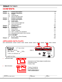
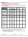
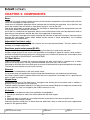
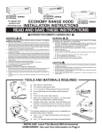
APPLIANCE DATA PLATE
1
1
LFT 228 A7HA
220-240 V 50 Hz
MAX.1900 W
2
2
37464540200 S/N 70614 1476
1800 W
19506353401
0,03 : 1MPa
TYPE LS12-DEA601 S3
IEC 436
12
MADE IN ITALY
1
Industrial code:
37 46454 0200
Commercial and Technological modifications
Commercial code
Factory Code
2
Serial Number:
7 06
14 1476
Factory Correlative
Day of Manufacture
Month of Manufacture
Year of Manufacture
Service Manual
Manual LFF 825 IT/HA
Edition
2008.04.01
2
Language
English
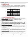
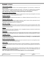
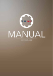
CHAPTER 1: PRODUCT DESCRIPTION
1 Upper rack
2 Upper spray arm
3 Flip-up shelves
1
3
4 Rack height regulator
4
2
5 Lower rack
6 Lower spray arm
7 Cutlery basket
5
6
8
7
9
1
10
10
11
11
8 Washing filter
9 Salt container
10 Detergent dispenser and rinse aid
dispenser
11 Data plate
12 Control panel
12
CHAPTER 2: GENERAL INFORMATION
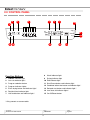
2.1: LEGEND
HOTPOINT / ARISTON:
L
K
L: Dishwasher
B: knob entry
xxxxxxxxxxxx K: knob basic
F: digit
D: LCD
F
F: 60 cm
S: 45 cm
7
2
A EN
#: n°.
1: basic features draining:
overflow
Programmes 2: medium
or: New
features
Acquastop
3: features
5: visible alarm
blank:
polar white
X: Stainless
steel
A: Aluminium
EN: market
HOTPOINT:
F
F: Full Size
S: Slimline
D
D: Dishwasher
L
D: LCD
F: Digit
L: LED
M: Mechanical
5
7
5: Aquarius
7: Acquarius +
9: Ultima
Number
Programmes
Service Manual
Manual LFF 825 IT/HA
Edition
2008.04.01
3
O
Series: 0-9
P
P: Polar
G: Graphite
A: Aluminium
K: Black
Language
English
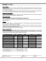
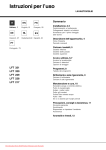
2.2. CONTROL PANEL
2
3
4
5
6
7
8
1
9
10
15 14
13
12
11
Function Buttons
8
Wash indicator light
1
ON/OFF indicator light
9
Drying indicator light
2
Low salt indicator light *
10 End indicator light
3
Program selection button
11 Start/Pause button and indicator light
4
Program Indicator Lights
12 Combined action tabs button and indicator light *
5
Extra drying button and indicator light *
13 Delayed start button and indicator light *
6
Residual time indicator light
14 Low rinse aid indicator lights *
7
Half load button and indicator light *
15 On-Off/Reset button
* Only present on some models
Service Manual
Manual LFF 825 IT/HA
Edition
2008.04.01
4
Language
English
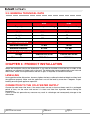
2.3: GENERAL TECHNICAL DATA
Technical Data
EU
Capacity
UK
12 standard place settings 12 standard place settings
Dimensions
Width
59.5 cm
59.5 cm
Height
82 cm
82 cm
Depth
57 cm
57 cm
Maximum Pressure
10 bar
10 bar
Minimum Pressure
0.5 bar
0.5 bar
Voltage
220/230 Volt 50 Hz
220/240 Volt 50 Hz
Minimum Power
1900 Watts
1900 Watts
Water Connections
Electrical Connections
CHAPTER 3: PRODUCT INSTALLATION
Select the installation site for the dishwasher: it can also be installed so that the rear or sides of the
appliance are adjacent to kitchen units or the wall. The dishwasher comes supplied with water inlet and
drain hoses, which can be positioned to the left or right, as required, to facilitate installation.
LEVELLING
Having positioned the dishwasher, loosen or tighten the feet to achieve the desired height and then level
the appliance properly. Make sure the appliance is not off the level by more than 2 degrees. Proper
levelling ensures good appliance operation.
CONNECTION TO THE COLD WATER SUPPLY
Connect the cold water inlet hose. If the water hoses are new or have not been used for a prolonged
period of time, run the water and ensure it is clean and free from impurities before making the
connections.
Failure to take this precautionary measure may result in a blockage and consequently damage to the
dishwasher.
Service Manual
Manual LFF 825 IT/HA
Edition
2008.04.01
5
Language
English
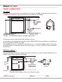
DRAIN CONNECTION
Standpipe
Make sure that the drain hose is not inserted too far inside the standpipe. If the end of the drain hose is
provided with “support fins”, make sure these are fully inserted in the standpipe.
120
min
65 mm (2 ½”) max.
40 mm (1 ½”) min.
Recommended height for
standpipe 500 mm (20”)
FIGURE:
Recommended height for standpipe: 500mm (20’’)
This prevents the hose from jolting during installation and use.
Do not position the standpipe near electrical sockets. MAKE SURE that the drain hose is not kinked and
that it is positioned as shown in the figure.
The standpipe must have a diameter of at least 38 mm (1½’’). It must be installed as shown in the figure,
be provided with a trap and drain into the same drain system as the sink. IT MUST NOT be connected to
the sink drain.
Sink drain system
For draining below the sink:
Before connecting the drain hose, eliminate any internal restrictions in order to prevent the build-up of any
foreign material which could lead to blockages.
800 mm
(31 ½ In.)
min.
FIGURE:
Spigot height
600 mm min.
Fit hose to waste
securely using a
‘Jubliee type clip
Tap height 600 mm min.
Fix the drain hose securely using a hose clamp with screws.
Service Manual
Manual LFF 825 IT/HA
Edition
2008.04.01
6
Language
English
Eliminate any restrictions in the drain trap and make sure the plug has been removed. The hose must be
positioned so that it sits at a minimum height of 800 mm (31½’’).
NOTE:
1.
2.
3.
4.
Make sure that the sink drain pipe has a minimum diameter of 32 mm.
Unfasten the end of the GREY drain hose from the rear of the appliance.
Connect the GREY drain hose to the support bend, as shown.
If installing the drain system below the sink, cut the membrane, plug or cover.
Fit the drain hose securely to the waste below the sink.
Service Manual
Manual LFF 825 IT/HA
Edition
2008.04.01
7
Language
English
CHAPTER 4: PRODUCT DESCRIPTION
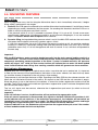
4.1. PROGRAMMES
Indications for
programme selection
Heavily soiled crockery
and pans (not for delicate
items).
Crockery and pans with
normal soiling. Standard
daily programme.
Reduced load of crockery
with normal soiling (4
place settings + 1 pot +
1 pan).
Pre-wash, for load to be
completed at a later stage.
Energy-saving eco wash,
suitable for crockery and
pans.
Quick, energy-saving
cycle for lightly soiled
crockery to be washed
immediately after use.
(2 plates + 2 glasses +
4 cutlery items +1 pot +
1 small pan).
Quick, energy-saving
cycle for delicate crockery
more sensitive to high
temperatures, to be
washed immediately.
(12 long-stemmed
glasses + fine plates).
Sanitizing cycle for
washing baby bottles and
accessories (rings and
teats) together with plates,
cups, glasses and cutlery.
Load the dishes in the
upper rack.
Programme
Detergent
(A) = dispenser A
(B) = dispenser B
powder
liquid
tabs
Programme
with drying
cycle
Options
Programme
duration
(margin
±10%)
Intensive
30 g (A)
30 ml (A)
1 (A)
Yes
A-B-C-D
2:15’
Normal
25 g (A)
5 g (B)
25 ml (A)
5 ml (B)
1 (A)
Yes
A-B-C-D
1:45’
Daily a 60°
25 g (A)
25 ml (A)
1 (A)
No
A-B-C
1:00’
Soak
No
No
No
No
A-B
0:08’
Eco *
25 g (A)
5 g (B)
25 ml (A)
5 ml (B)
1 (A)
Yes
A-B-C-D
2:20’
Speed
25 g (A)
25 ml (A)
1 (A)
No
A-C
0:25’-0:35’
Glass
30 g (A)
30 ml (A)
1 (A)
Yes
A-B-C-D
1:30’
Baby cycle
20 g (A)
20 ml (A)
No
Yes
A
1:20’
N. B.:
1
2
3
The number and type of programmes may vary depending on the dishwasher model.
“Washing times” are adjusted automatically based on the wash options selected by the use and the
degree of soiling of crockery being washed
“Washing times” are adjusted automatically based on the wash options selected by the use and the
degree of soiling of crockery being washed.
Service Manual
Manual LFF 825 IT/HA
Edition
2008.04.01
8
Language
English
4.2. WASH OPTIONS
The table specifies all the options available on EOS Platform dishwashers and compatibility /
incompatibility of all options with all programs.
Always check the user handbook of individual models to see which options are present and to check
compatibility with the various programs.
A
Delayed
Start
Intensive
Normal
Daily a 60°
Soak
Eco
Speed 25’
Glass
Baby cycle
YES
YES
YES
YES
YES
YES
YES
YES
B
C
D
Half Load Combined Extra Dry
Action
Tabs.
YES
YES
YES
YES
YES
YES
YES
YES
NO
YES
NO
NO
YES
YES
YES
NO
YES
NO
YES
YES
YES
NO
NO
NO
4.3. HOW TO USE THE APPLIANCE
Starting a programme:
Use the programme selector to select a programme, then press the Start/Pause button.
Resetting the programme in progress:
Long press the On/Off button, the appliance will emit a long beep, indicating that the program has been
reset.
Important: in the previous EVO 3 Platform, appliances were Reset by long pressing the “P” button
(program selection button). REMEMBER THAT IN THE EOS PLATFORM, IF YOU LONG-PRESS
BUTTON “P” IMMEDIATELY AFTER SWITCHING ON THE DISHWASHER, YOU ACCESS THE
WATER HARDNESS SETTING MODE AND THE MACHINE WILL NOT RESET.
Changing a programme in progress:
If you have selected the wrong programme, you can change it as long as it has only just started: to change
the wash programme which has just started, long press the ON/OFF/Reset button to switch the appliance
off, switch it back on again with the same button, select the desired programme and options, then press
the start/pause button.
Adding more crockery:
Press the Start/Pause button, (the corresponding indicator light flashes). Open the door, bearing in mind
hot steam may exit, and insert the crockery. Press the Start/Pause button again: the wash cycle starts
again after a long beep.
Accidental interruptions:
The programme is interrupted if the door is opened or if there is a power cut. When the door is shut or the
power supply restored, the dishwasher will resume the wash cycle from where it was interrupted.
Service Manual
Manual LFF 825 IT/HA
Edition
2008.04.01
9
Language
English
4.4. INNOVATIVE FEATURES
Water filling:
When a programme starts, the first thing the dishwasher does is drain. Immediately afterwards, it begins
filling, which is performed in two stages:
1.
Static fill: the PCB opens the solenoid valve and the dishwasher loads between 2.5 and 3 litres of water
(depending on model), checked by the litre counter. On reaching this threshold, the Main PCB runs a
check to verify that the pressure switch is on full.
If the pressure switch is on full, it proceeds to dynamic filling; if it is not on full, it loads more water,
approximately 100cc more. If the pressure switch is on full, dynamic filling begins, if not, the machine
signals a Pressure Switch Non Compliant alarm condition.
2.
Dynamic filling: having checked the pressure switch is on full, the Main PCB activates the wash motor
and opens the fill solenoid valve until it reaches approx. 4 litres.
If, after this second filling, the main PCB senses the pressure switch on full, the machine continues
washing. If it does not, it continues loading water until the pressure switch is on full or up to 5.5 litres
(whichever occurs first). If it is full, the appliance will wash as normal. If not, it will drain and proceed to
the next step.
Important:
With the EOS platform, water cannot be loaded manually into the tank: manual loading results in a
“Turbine Alarm”. The litre counter turbine and the pressure switch function independently, with one
component monitoring correct operation of the other: if water is loaded manually, the pressure
switch will signal “full” while the litre counter turbine will indicate that no water has been loaded
since it did not detect water filling, thus creating a conflict which will generate an alarm condition.
Salt Indicator Management:
Regeneration salt is managed by an optical sensor with a transmitter led and a receiver led. It is important
to note that the sensors are not positioned on the bottom of the water softener, but about half-way down
(to avoid the chance of impurities in the salt giving a false reading).
The presence of salt interrupts the beam of light, signalling to the Main PCB that the softener contains salt.
When the salt falls below the level of the sensor, this signals to the PCB that the salt container is empty.
Since the sensor is not on the bottom of the softener, in actual fact further regeneration cycles will still be
possible. The PCB will switch on the indicator light when 6 regeneration cycles have been completed since
the salt container empty signal.
The "no salt" signal must be constant, otherwise the 6 regeneration cycle count (to switch on the salt
indicator), starts over.
Important:
If the salt indicator is not on, the dishwasher will not perform the regeneration cycle.
If the salt sensor\ connector is disconnected, this signals to the Main PCB that the container is full,
so the indicator will not switch on. If the technician reconnects it, the indicator will not switch on
immediately even if the salt container is empty. The Main PCB will detect this situation and begin
counting the 6 regeneration cycles, after which it will switch on the salt indicator.
If the salt indicator is on, the dishwasher will not perform the regeneration cycle, even if the number
of litres loaded exceeds the limits set by Editor.
Service Manual
Manual LFF 825 IT/HA
Edition
2008.04.01
10
Language
English
Rinse Aid Indicator Management:
The sensor used in the EOS platform for management of Rinse Aid is a Magnetic Reed Switch located
inside the rinse aid dispenser. It uses a float to monitor the presence of rinse aid.
The User Interface takes the sensor reading, conveying the data to the Main PCB; the latter decides whether
to switch the indicator on or off and signals the data to the User Interface, which will switch it on or off.
Setting water hardness:
Unlike previous platforms, where regeneration is performed with every wash cycle (except soak); with the
EOS Platform regeneration is performed based on the appliance conditions/operation settings.
When the appliance is installed, or when the Main PCB is replaced, water hardness MUST be set in order
to guarantee proper appliance operation and to prevent depletion of the resins contained in the softener.
The factory default setting for water hardness is “3”, which corresponds to 30° French degrees, with
regeneration every 65 litres of water loaded.
If using combined-action tabs:
Set water hardness as when using any other detergent, if using combined action tabs fill the salt
container in any case.
WATER HARDNESS
°d
fH
mmol/l
LEVEL
Hardness
N° Litres
0
6
0
10
0
1
1
1
150
6
11
11
20
1.1
2
2
2
100
12
17
21
30
2.1
3
3
3
65
17
34
31
60
3.1
6
4
4
30
34
50
61
90
6.1
9
5
5
7
From 0°F to10°F the use of salt is not recommended
How to set the water hardness level in 6-LED appliances:
In appliances with Led interface without knobs, water hardness is set as follows:
1. Switch the dishwasher on (On/Off button)
2. Press button “P” for 6 seconds; the appliance will emit an acoustic signal and the indicator light for the
set hardness will flash; as in Built In machines
3. Next press button “P” until you reach the desired hardness
4. To exit water hardness setting, switch off the dishwasher or wait for 30 seconds.
Note.: The factory default setting for water hardness is 3.
Important: Resin regeneration is not carried out at every cycle as it was in previous Platforms, but
based on the water hardness setting and the amount of water loaded and only with certain
programmes (so for example, not with the soak programme). If the number of litres of water loaded
exceeds the Editor setting for the particular hardness selected (see attached Table) at the end of
the cycle the appliance will run the resin regeneration cycle.
Service Manual
Manual LFF 825 IT/HA
Edition
2008.04.01
11
Language
English
REGENERATION PROCEDURE:
1. Load a certain amount of water (approx. 90cc), activating the solenoid valves (fill and regeneration)
in order to direct the flow through the salt, thus flushing brine through the resins. Then shut the
solenoid valves.
2. Wait about 10 minutes.
3. Load a second amount of water (about 190cc), in the same way.
4. Wait 5 minutes.
5. The next step is to wash the resins, flushing between 1 and 2 litres of water over them, activating only
the fill solenoid valve and not the regeneration solenoid valve.
6. Final draining.
Important: It is important to bear in mind that each time the Main PCB is replaced, the litre count
for management of water hardness setting is lost, and must therefore be reset.
Water softening may be less than optimal for another few cycles.
Drying phase:
The drying system operates on the same principle as that on EVO 3 dishwashers. In the last phase, the
appliance runs a hot rinse, activating the wash element. The water will reach a high temperature, which
will depend on the programme chosen, for example it will reach 70°C for certain programmes but will not
exceed 64°C with the “Baby Cycle”.
Next, a certain period of time is allowed to pass with water in the tank so that the crockery drains and the
steam condenses on the walls. The liquid rinse aid (that placed in the rinse aid dispenser by the user),
plays an important part in drying performance, helping water to “run-off” dishes.
The drying phase includes a certain period of time with no water in the tank.
Note.: Excellent washing and drying results can be obtained by using powder detergent and liquid
rinse aid.
“Extra Dry” Option:
Free Standing appliances with led interface may also feature the “Extra Dry” option”. Choosing this option
extends the duration of the drying phase with no water in the tank by 10-20 minutes (depending on the
programme selected).
Nonetheless, the drying temperature remains unchanged.
Blocked Filters:
If the filters become clogged or the user inserts a pot facing upwards, the Pressure Switch may signal
empty.
In this case, in the Evo 3 platform the dishwasher proceeded to “Filter Cleaning”; in this platform no such
routine is present, so the appliance will load water until the pressure switch signals full again or until
5.5 litres of water have been loaded. In this case (5.5 Litres loaded) the dishwasher will drain and proceed
to the next wash step. In the event of chronically clogged filters, the user may call to report crockery still
being dirty at the end of a wash cycle.
Advice for the Call Center:
1. wash the filters
2. Position pots upside down and try washing again
Service Manual
Manual LFF 825 IT/HA
Edition
2008.04.01
12
Language
English
CHAPTER 5: COMPONENTS
Base:
The base is a plastic structure which contains all the functional components of the dishwasher and also
serves as the support for the wash tank.
In the base of integrated appliances there are three feet for levelling the appliance, two at the front and
one in the middle at the rear which is adjusted by means of a nut at the front.
One of the advantages of the new base is the possibility of accessing the motor compartment from the
Front Door, which is secured with two hooks.
As for the Pan, underneath the appliance, there are two further hooks which must be released in order to
open the pan and remove it towards the front of the appliance for dismantling.
Note.: In the even of damage to the hooks securing the front door of the base or the pan, the base can be
secured with self-tapping screws which enable correct closure of these components, thus avoiding
replacement of the entire base.
Adjustable Feet (front only):
The feet, 2 in total, are for levelling the machine and must be adjusted directly. The rear section of the
machine is not height adjustable.
Brushless wash motor pump (BLDC):
Featured on TOP of range machines. The principal characteristic is quiet motor operation.
Another unique feature of this motor is the possibility of managing its speed of rotation, which makes it
possible to change the water pressure for washing and, thus, to add wash options like, for example, those
used in this platform (GOOD NIGHT and SHORTIME).
AC Wash Motor:
The AC wash motor is tasked with managing washing with both water inlets in a specific way. It directs
water first to the top spray arm only, then to the bottom spray arm only, and so forth.
If the program lasts less than 1 hour, both spray arms wash at the same time to guarantee optimal wash results.
The user can also choose to wash in one rack only.
Element:
The element is fitted directly to the wash pump volute.
It can be removed and replaced by simply turning the element/motor anti-clockwise and removing.
An O-ring is fitted in order to prevent water leaks: be sure to reposition it and check it is in a good state of
repair in order to prevent leaks.
Acqua Stop:
Positioned at the start of the feed hose, it manages water loading into the machine and, in addition, it
prevents filling in the event of a malfunction.
The flow capacity has been reduced to 2.5 litres per minute, hence filling time is longer but compensated
by quiet operation. This is managed by the PCB by means of a triac.
Air break:
The Air break is located on the left of the appliance; it is designed to:
1. Prevent the backflow of water from the machine into the water supply.
2. Vent
3. Permit the entry of around 3% of unsoftened water to prevent the formation of excess suds
4. House the Litre-Counter Turbine
Unlike the previous model, this Air break does not hold water. Bear in mind that the resin regeneration
process in this platform differs.
Service Manual
Manual LFF 825 IT/HA
Edition
2008.04.01
13
Language
English
Litre-counter turbine:
As in Evo 3, it monitors the amount of water entering the appliance. This information is verified by the
pressure switch.
Every 270 impulses emitted by the turbine equals approx. 1 litre of water. This setting will have a correction
value of around 2 %. Where the water pressure is lower than 1 bar, the correction value will be 6 %.
Note.: Below 0.5 Bar, the litre-counter reading system might not work properly.
Regeneration Solenoid Valve:
It is fixed to the water softener and its function is to allow the flow of water to pass through the salt in order
to collect brine, which is used to regenerate the resins.
Pressure switch:
The pressure switch, although physically identical, has a different calibration from that of EVO 3, so it is
not interchangeable.
Pressure switch hose:
Special hooks have been designed to keep the pressure switch in place and thus guarantee the seal,
ensuring the hose does not fall and risk filling up with water.
The hose must be inserted so that it is not overly taut.
RFI Filter & Plug:
There are two kinds of electrical socket, one for the European market and one for the UK market. There
are also two kinds of filter, one for the synchronous wash motor and another for the BLDC motor (in total
4 different spare part codes).
Wiring:
Wiring is specific for each type of dishwasher, and is managed by the spares warehouse in odd volumes
(like those of washing machines and EVO 2).
Reservoir:
The reservoir is very different from that on Evo 3 and is fixed to the tank with 4 screws. It is designed to house
other components, for example: Drain Pump, Turbidity Sensor, Drain Hose, AC Wash Motor, NTC, Air trap.
Turbidity sensor:
Although physically different, it performs the same functions as in Platform Evo 3, i.e. it gauges the level
of soiling of crockery in order to establish the wash characteristics accordingly. It is sited in the reservoir,
in direct contact with the water.
Spoiler and water diverter:
Designed to limit suction of water during the wash cycle, it prevents the motor from running without water.
It uses basket filters over the entire filter surface.
Drain hose:
The drain hose is connected to the reservoir by means of a press-fit connection. 2 O-rings seal the connection.
The antirelease mechanism consists of hose fixture using a mechanical blocking device on the lower rear
crosspiece.
Hinges:
The hinges used in free standing appliances are self-balancing. The right and left hinges are different and
are easy to fit/remove compared to those used in previous platforms. They are located between the wash
compartment (rack) and the plastic support.
Note.: The hinges of built-in and free-standing appliances are not interchangeable.
Service Manual
Manual LFF 825 IT/HA
Edition
2008.04.01
14
Language
English
Drain Pump:
the new Drain Pump does not have a volute assembly so the wash impellers are uncovered. It must be
fitted directly to the reservoir. The drain hose too is connected directly to the reservoir and not to the Pump
as in the previous platform.
A small hole has been provided in the upper section where the Drain Pump is attached, in order to prevent
the formation of “Air Bubbles” which result in cavitation (working without pumping water).
Detergent Dispenser:
Physically and functionally identical to that of Evo 3. With double catch system; the first catch for opening
the cover and the second (double) for adding rinse aid.
Anti-flood float:
Functionally identical although physically different to that used in Evo 3.
From an electrical point of view, it is normally closed, (unlike EVO3).
When activated by water in the pan (switch electrically open), the dishwasher will drain and activate an
“Overflow” alarm.
Filters:
There are 3 filters: the first (1) is made of steel and is flat, much larger than those in the previous platform
in order to prevent it becoming easily clogged.
The second (2) is a basket filter, similar to that on the previous platform; and the third (3), the microfilter,
which in this case does not rotate but is fixed.
In order to exploit the entire filtering surface of these last two filters, a small “spoiler” has been fitted inside
the reservoir to direct water from all areas to the filters.
Other components
The other components, although physically different, perform the same functions as they did in
the previous platform (Evo 3). This does not mean that they are interchangeable, since technical
characteristics will differ (for example: the pressure switch).
Electrical Component
Volts
Frequency
Watts
Ohm
Amp
Fill solenoid valve
220/240
50/60 Hz
+/- 8 W
3720 Ω
0.03
Acquastop Solenoid Valve
220/240
50/60 Hz
+/- 8 W
4130 Ω +/- 10% (20°C)
0.03
Regeneration Solenoid
220/240
50/60 Hz
+/- 7 W
4109 Ω
0.02
Dispenser Solenoid
220/240
50 Hz
---
1619 Ω
0.19
Drain Pump
220/240
50 Hz
26 W
216 Ω +/- 7%
0.03
Synchronous Element (all Mkt) (3)
220/240
50 Hz
1800 W +/- 5%
29.2 Ω +/- 5%
8
Synchronous Element (Uk) (2)
220/240
50 Hz
1800 W +/- 5%
31.8 Ω +/- 5%
8
BLDC resistor (4)
220/240
50 Hz
1800 W +/- 5%
31.5 Ω +/- 5%
8
---
---
---
---
---
(1) The Brushless motor cannot be inspected. The motor is controlled by an internal electronic circuit board.
(2) Thermoprotector: 95° C +/- 5° C - Thermofuse: 206° C +/- 10° C
(3) Thermoprotector: 95° C +/- 5° C - Thermofuse: 206° C +/- 10° C
(4) Thermoprotector: 95° C +/- 5° C - Thermofuse: 206° C +/- 10° C
Service Manual
Manual LFF 825 IT/HA
Edition
2008.04.01
15
Language
English
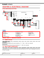
CHAPTER 6: ELECTRICAL DIAGRAM
SYNCHRONOUS MOTOR
(CN01- 2 )
(CN01-3 )
TIMER DEA 601
LINEA IP (CN02-1)
1
CN02
E
PIENO
(CN02-2)
VUOTO
(CN02-3)
RR
(CN02-4)
RR
(CN02-5)
V
1 2 3 4 5 6 7 8 9 1 01 11 21 31 4 1 2 3 4 5 6 7 8 9
REF
GND
SCL_BUS
LINEA IP
TX
RX
SDA_BUS
CN08
1
1
123
H
+ VCC
NEUTRO
LINEA _IP
TRIAC ALT.
TX
RX
+ 12 VOLT
REF
H2O STOP
TURBINA
LINEA IP
LINEA IP
RIGENERA
EV CARICO
GND
INPUT
4 3 2 1
G
CN07
CN06
CN11
DISPENSER
CN05
CN04
1
+ VCC
LINEA IP
LINEA
POMPA LAV
CN03
F
POMPA SC
D
LINEA
LINEA
LINEA IP (CN01-4)
5 4 3 2 1
4 3 2 1
CN01
B
C
NEUTRO (CN01- 1)
1
220/240V 50 HZ
A
1
123
12345678
U
L
I
N
M
S
O P
R
Q
Legend
A
B
C
D
E
Mains power
RFI filter
Door Switch
Pressure switch
1 Shared
2 Full
3 Empty
Thermofuse (206 °C)
F
G
H
I
L
M
N
O
Wash Element
Thermoprotector (95 °C)
Drain Pump
Wash Motor Pump
Salt Reed Switch
Fill Solenoid
Regeneration Solenoid
Overflow Switch
P
Q
R
S
T
U
V
Litre-counter Turbine
Duo Wash motor
Turbidity sensor
Dispenser Solenoid
Interface
Rinse Aid Reed Switch
NTC
CHAPTER 7: ASSISTANCE
7.1. DEMO MODE
In Digit Appliances:
Activation:
Starting with the appliance off, press the buttons: “P” + “Tabs” + “Start” for 6 seconds.
Deactivation:
Starting with the machine off, press the buttons “P” + “Start” for 6 seconds.
7.2. AUTOTEST FUNCTION
The new electronic EOS platform does not have the integrated long autotest function that we are familiar
with (“ROD”); it can only start and test dishwashers with the short “SAT” cycle. A description of how this
is done is provided.
Service Manual
Manual LFF 825 IT/HA
Edition
2008.04.01
16
Language
English
7.2.1. SAT” AUTOTEST START SEQUENCE”
Start with the appliance off and the door open:
1. Switch the dishwasher on ( On/Off key).
2. Switch the dishwasher off ( On/Off key).
3. Press button “P” for 3 seconds
4. Switch the dishwasher on (On/Off button)
5. Press the Start/Pause button.
Note.: If the dishwasher door is opened during the Autotest cycle, it will remain in Running mode.
7.2.2. SEQUENCE PERFORMED BY THE MACHINE
If there are no faults in the “ Last Fault” memory, the following steps execute when the autotest is run:
1. Tank emptied until pressure switch empty + 30 seconds.
2. AC wash motor positioned at “zero” (both water inlets open).
3. Static filling of 3.1 litres of water.
4. Dynamic filling of 1.1 litres of water.
5. Wash pump runs for 60 seconds and water filled via pressure switch to a total of 5.5 litres.
6. Wash pump stops.
7. Heating element activated for 10 seconds.
8. Dispenser activated for 10 seconds.
9. Wash pump activated for 10 seconds.
10. Regeneration solenoid activated for 15 seconds (alone).
11. Tub emptied to pressure switch empty + 5 seconds.
12. Turbo Dry activated for 10 seconds (when installed, otherwise nothing will happen for 10 seconds).
13. The fill solenoid and the drain pump are activated together for 20 seconds ("blowing") in the production
line to empty the hydraulic circuit.
If a fault has been saved to the “Last Fault” memory, the appliance will display the fault for the first
15 seconds when the Autotest sequence is run, after which the previously described sequence will
commence automatically. At the end of the autotest, the fault will be deleted from the “Last Fault” memory”;
otherwise, if the autotest sequence is stopped while it is still running, the last fault will remain in the
memory and will be displayed again when a new Autotest is run.
Service Manual
Manual LFF 825 IT/HA
Edition
2008.04.01
17
Language
English
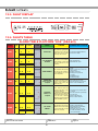
7.2.3. FAULT DISPLAY
7.2.4. FAULTS TABLE
ALARM TABLE PLATFORM “EOS” (DEA 601)
!,!2-
!,
!,
$IGIT ,%$
,%$
,%$
.!-%
/6%2&,/7
&),,3/,%./)$
"2/+%.
!,
$2!). 4)-%/54
!,
4(%2-)34/2
.4#CIRCUITNOT
COMPLIANT
!,
!,
#!53%
#/22%#4)6% !#4)/.3
4HE0#"HASREGISTEREDTHE
ELECTRICALCLOSUREOFTHEPAN ,EAKFROMLOCKNUTJOINTTANKETC
mOAT SENSOR %G mOAT HAS &LOAT3ENSORFAULTY
MOVEDUPDUETOALEAK
4HEMAIN0#"HASREGISTERED
THE ROTATION OF THE TURBINE
&ILLSOLENOIDBROKEN
WATERmOWINGEVENTHOUGH
-AIN0#"4RIACSTUCK
THE FILL SOLENOID WAS NOT
ACTIVATED
&OREIGNBODYBLOCKINGTHEDRAIN
PUMP
0UMPCONNECTORDISCONNECTEDOR
4HEMAXIMUMTIMEALLOWED
FALSECONTACT
FOR THE 0RESSURE 3WITCH TO
$RAINHOSEBLOCKED
REACH %-049 HAS BEEN
$RAINPIPENOTPOSITIONED
EXCEEDEDMIN
CORRECTLY
!IRBUBBLEINHOSE
$RAINPUMPFAULTY
4HEMAIN0#"HASREGISTERED
A FAULT IN THE .4# CIRCUIT .4#CABLESDISCONNECTED
! SHORT CIRCUIT # OR .4#SHORTCIRCUITOROPENCIRCUIT
BROKEN CABLE # HAS &ALSECONTACTIN0#"LEADS
BEENDETECTED
02%3352%
37)4#(NON
COMPLIANT
4 H E M A I N B O A R D H A S
REGISTERED THE FAILURE OF THE
PRESSURESWITCHAS
$URINGSTATIClLLINGAFTER
LITRESTHEPRESSURESWITCHDID
NOTMAKETHE&5,,CONTACT
!T THE END OF HEATING
TIMEOUTTHEPRESSURESWITCHIS
STILLINTHE%-049POSITION
&),,7!4%2
4)-%/54
4URBINECONNECTORDISCONNECTED
4URBINECABLESDAMAGED
4HETIMEALLOWEDFORWATERTO
-AIN0#"WATERMETERTURBINE
lLLANDFORTHE0RESSURE3WITCH
4URBINEFAULTYORWET
TOREACH&ULLSECONDS
-ORETHANLITREOFWATERHAS
HASBEENEXCEEDED
BEENlLLEDMANUALLYTOTHETUB
NOTRECOMMENDED
Service Manual
Manual LFF 825 IT/HA
Edition
2008.04.01
18
#HECKIFPRESSURESWITCHISSTUCK
ONEMPTY
0RESSURESWITCHHOSEPUNCTURED
DISCONNECTED
3UMPAIRTRAPBLOCKED
%XCESSSUDSINMACHINE
Language
English
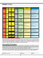
!,!2-
!,
!,
!,
$IGIT ,%$
,%$
,%$
.!-%
#!53%
#/22%#4)6% !#4)/.3
4URBINEDAMAGED
4HEMAIN0#"HASDETECTED
WATER IN THE TANK VIA THE
PRESSURE SWITCH WITHOUT
RECEIVINGANYASSOCIATEDlLL
SIGNALFROMTHETURBINE
4URBINECONNECTORDISCONNECTED
4URBINECABLESDAMAGED
-AIN0#"WATERMETERTURBINE
4URBINEFAULTYORWET
-ORETHANLITREOFWATERHAS
BEENlLLEDMANUALLYTOTHETANK
NOTRECOMMENDED
4%-0%2!452%
4)-%/54
4HEMAXIMUMTIMEALLOWED
TO REACH THE REQUIRED
TEMPERATUREINTHISPHASE
HOURHASBEENEXCEEDED
.OTE *UST BEFORE THE
ALARMTHEPRESSURESWITCHIS
STILLINTHE&5,,POSITION
.4#DISLODGED
(EATINGELEMENTFALSECONTACT
FAULTY
)42NOTCALIBRATEDPROPERLY
%CCESSSUDSUNSUITABLE
DETERGENTS
3OFTWARE
RECOGNITION
ERROR"OARDNOT
PROGRAMMED
.OSETTINGlLEFOUND
,OADASETTINGlLEUSINGASMART
CARDOR0$!
4HE-AIN0#"HASREGISTERED
THEELECTRICALOPENINGOFTHE
HEATING CIRCUIT ELEMENT
)42WIRINGx
.OTE
!LARMACTIVEWHENHEATER
RELAYNOTINSERTED
4HE OPEN CIRCUIT SIGNAL
MUST BE PRESENT FOR MINUTES
(EATERFAULTY
#ABLESDISCONNECTEDINHEATER
CIRCUIT
(EATERCONNECTORDISCONNECTED
ONTIMERSIDE
-AIN0#"RELAYFAULTY
!,
(%!4).' %,%-%.4
CIRCUITNOTCOMPLIANT
!,
7ASH0UMP
"REAKDOWN
#/--5.)#!4)/.
ERRORBETWEENMAIN
0#"ANDDISPLAY
0#" ./4
!,
!,
4 H E M A I N B O A R D H A S #HECKCONNECTORSONTHEMAIN
REGISTERED A FAULT IN THE 0#"PUMPSIDE
ELECTRONICELECTRICCIRCUITFOR #HECKCONTINUITYOFCABLES
THE",$#MOTOR
2EPLACEWASHPUMP
.OCOMMUNICATIONBETWEEN
MAIN 0#" AND DISPLAY
CARD
#HECKCOMMUNICATIONCABLES
BETWEENMAIN0#"ANDDISPLAY
CARD
$ISPLASYFAULTY
2ENEW0#"
7.3. PC, PALM, SMART READER
EOS Electronic Platform dishwashers are fitted with the DEA 601 Main PCB. An update of the DEA 600 Main
PCB used in Seven Digit appliances. Two types are available, one for models with synchronous motor and
another for models with BLDC motor. The PCB is located at the rear part of the door, secured with a snap-in
fastening. To release it, simply push the PCB gently at the connectors side.
How is the Main PCB managed?
The Main PCB is supplied unprogrammed, so if the market does not have PDAs or PCs, technicians will have to
use the Smart Reader and ask the spare parts warehouse for the specific Main PCB plus Smart Card for the
appliance. Eeprom will not have to be used. The Setting File will be registered directly in the PCB microprocessor.
The PCB will have to be installed (observing safety standards), after which it can be programmed. In any case,
consult the documentation relating to the use of the programming device being utilized.
Very Important: When working on the Main PCB, close the front door: it is very important to make sure
that the wires of the PCB do not create mechanical interference with the float. This could block it.
Service Manual
Manual LFF 825 IT/HA
Edition
2008.04.01
19
Language
English
CHAPTER 8: DISASSEMBLY
Detergent Dispenser:
1
2.
3.
4.
Remove the 2 screws at the sides of the inner door and remove the front panel.
Remove the 2 screws on the front of the door, behind the exterior cover panel.
Disconnect the dispenser wires and remove the 6 screws that secure it to the inner door.
Remove the dispenser from the inner door, lifting it up out of its seat.
Display PCB:
1. Remove the 6 screws on the inner door.
2. Disconnect the display PCB wires.
3. Use a small flat blade screwdriver for leverage on the tab securing the control assembly-display PCB
and remove it.
4. Repeat the operation with the screwdriver on the other tab to remove the support altogether.
Inner Door and Hinges:
1. Remove the front panel.
2. Follow the procedure for Removing the Display PCB.
3. Insert a screw into the hole in the hinge (both sides of the machine) to block the door in a semi-open
position (for safety).
4. Using pliers, remove the tie, rotating it around its own fixing hole.
5. Remove the earth faston connected to the hinge.
6. Remove the 4 side screws (2 each side) that secure the hinges to the inner door and remove it.
7. Pull upwards to remove the inner door.
8. Disconnect earth fastons on the hinges.
9. Remove the screws (one left, one right), inside the appliance which secure the hinges to the wash tank.
10. Remove the four screws (two each hinge) which secure the hinges to the base of the dishwasher.
Pressure switch:
1. Remove the four screws (two front, two rear) which secure the right side panel.
2. Release the panel using a flat blade screwdriver for leverage (there are two hooks, one at the front
and one at the rear of the machine).
3. Dismantle the pressure switch, using a flat blade screwdriver for leverage.
4. Disconnect the pressure switch wiring.
Note.: when reassembling the pressure switch, take care to position the hose properly on its hooks.
Float:
1. Slide the PCB out, taking care not to disconnect the wiring.
2. Release the float, releasing the hook and removing it in the direction of the reservoir.
3. Disconnect the float connector.
RFI filter and support:
1. Remove the four screws (two front, two rear) which secure the right side panel and remove the panel.
2. Remove the filter, sliding it out along its support runners.
3. Disconnect the RFI filter.
Service Manual
Manual LFF 825 IT/HA
Edition
2008.04.01
20
Language
English
4. Insert a small screwdriver or the tip of a tester into the hole next to the support to lift the hook securing
the support, then slide it in the direction indicated by the arrow.
Note.: be mindful of the wiring during dismantling and reassembly.
Fill Hose and Drain Hose:
1. Remove the four screws (two front, two rear) which secure the right side panel and remove the panel.
2. Turn the appliance upside down.
3. Remove the pan by releasing the tabs securing it to the lower support and sliding it out towards the
front of the dishwasher.
4. Insert a flat blade screwdriver to release the tab securing the hose support.
5. Lift up the cover and remove it.
6. Pull the drain hose to remove it from its seat (it is pressure-inserted).
7. Remove the clamp that secures the feed hose to the Air break and remove the hose.
Air break & Softener:
1. Remove the four screws (two front, two rear) which secure the right side panel and remove the panel.
2. Remove the ring nut that secures the Air break to the dishwasher tank.
3. Disconnect the Litre Counter Turbine connector.
4. Remove the Air break.
5. Remove the clamp that secures the feed hose to the Air break.
6. Remove the plug and ring nut of the softener.
7. Disconnect the regeneration valve and release the softener from its support hook.
8. Rotate the softener, lifting it up to remove it laterally.
Note.: be careful with the Air break feed hose, pushing it in towards the base in order to prevent the
softener disengaging.
10. Disconnect the salt reading module.
11. Remove the softener-reservoir hose clamp.
12. Remove the softener.
Reservoir:
1. Remove the filters and the lower rotor.
2. Remove the two fixing screws of the top rotor delivery hose to release it from its coupling.
3. Remove the four screws of the reservoir ring nut and remove it.
4. Turn the machine upside down and remove the pan.
5. Carry out the disassembly of the AC wash motor.
6. Carry out the disassembly procedure of the electric wash pump.
7. Remove the drain hose and unscrew the drain pump.
8. Disconnect the conductivity sensor.
9. Disconnect the NTC.
10. Remove the reservoir
Top rotor delivery:
1.
2.
3.
4.
Remove the racks.
Remove the filters and the bottom rotor.
Remove the two fixing screws of the top rotor delivery hose to release it from its coupling.
Use a flat blade screwdriver for leverage at the side in order to release the upper rotor delivery hose
from its seat.
Service Manual
Manual LFF 825 IT/HA
Edition
2008.04.01
21
Language
English
Electric wash pump:
1. Turn the machine upside down.
2. Release the pan.
3. Release the float.
4. Use pliers to open the clamps.
5. Remove the electric wash pump by disengaging the rubber support from its seat.
6. Disconnect the heating element earth connection.
7. Disconnect the resistor power supply.
8. Disconnect the motor feedback wire.
9. Disconnect the power to the motor.
10. Remove the electric wash pump.
Disassembly of the AC wash motor:
1.
2.
3.
4.
5.
6.
7.
Turn the machine upside down.
Release the pan.
Pull out the rear foot adjustment rod.
Open the clamps and remove the AC wash motor hose.
Disconnect the motor terminal board.
Remove the three screws to dismantle the AC wash motor
Remove the AC wash motor, minding the O-rings.
Dismantling the Plinth
1.
2.
3.
4.
Open the door.
Remove the 2 screw (one each side) which fix the plinth to the dishwasher base.
Pull it gently at the bottom to release.
Remove completely.
Service Manual
Manual LFF 825 IT/HA
Edition
2008.04.01
22
Language
English
Service Manual
Manual LKF 72-71 LBF 51-5
Edition
2008.04.01
Language
English
GB