1
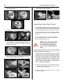
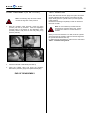
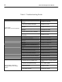
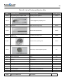
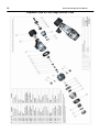
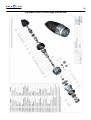
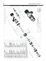
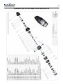
SERVICE MANUAL
KRONOS
FIRST STAGE
Copyright ©2006 Aqualung France
Ref : Service Manual-HP Kronos Rev. 07/2006
2
Kronos First Stage Service Manual
Index
COPYRIGHT............................................................................................................................... 3
INTRODUCTION........................................................................................................................ 3
WARNINGS, ATTENTION, NOTES..........................……………............................................... 3
MAINTENANCE.......................................................................................................................... 3
GENERAL INSTRUCTIONS........................................……........................................................ 3
GENERAL CONVENTIONS....................................................................………………….......... 3
DISASSEMBLY PROCEDURE................................................................…................................4
RE-ASSEMBLY PROCEDURE................................................................…................................7
ADJUSTING THE FIRST STAGE................................................................….............................9
FINAL ASSEMBLY…...................................................................................................................11
Table 1. Troubleshooting guide............................................……................................................12
Table 2. List of tools and service kits..................................................…………...........................13
Table 3. Recommended cleaners and lubricants................................….................................... 14
Procedure A. Cleaning and lubricating.........................................................................................15
Table 4. Torque settings......................................................................……….............................
16
Table 5. Checking specifications..........................................................……................................17
Exploded view of Kronos First Stage....…............................................……................................18
F I R S T
T O
3
D I V E
COPYRIGHT
GENERAL INSTRUCTIONS
This manual is the property of Aqualung France. Any
copying, photocopying, reproduction, translation, electronic
distribution (email, Internet...), even partial, and in whatever
format, is expressly forbidden without the written consent of
Aqualung France.
1.
In order to carry out the procedures described in this
manual correctly it is important that you follow the steps
in the exact order indicated. Read the manual through
completely so that you become familiar with all the
procedures, the special tools and the replacement parts,
before starting to disassemble the product. Keep this
manual open near to you so that you can refer to it step
by step. Do not rely on your memory.
2.
All servicing and repair procedures should be carried
out in a workshop that is clean, well lit, easy to access
and specially fitted for the purpose.
3.
The regulator body should never be directly held in the
jaws of a vice. To hold the body, screw the tool 006230
into the HP port and then grip the tool with the vice.
4.
Once the regulator has been disassembled, the reusable components should be separated from the
components that need to be replaced. Fragile items with
seats or crowns with critical sealing surfaces should be
separated and protected during servicing in order to
prevent any damage.
WARNINGS, ATTENTION, NOTES
5.
Certain icons have been used to facilitate the reading and
understanding of this manual. They have the following
meanings :
Use only spare parts from Aqualung service kits. Never
replace an Aqualung part with one from another
manufacturer, even if it appears similar.
6.
Never re-use regulator parts which should be replaced
on the pretext that the regulator has seen little use since
its manufacture or since its last service.
7.
When reassembling, check that the torque used
conforms with that shown in Table 4, Torque. Some
parts can be irretrievably damaged if the acceptable
torque is exceeded.
©2006 Aqua Lung France.
INTRODUCTION
This manual gives the instructions and the recommendations
for the disassembly, the cleaning, the checking, the
reassembly and the adjustment of an Aqualung regulator.
This manual is not an instruction manual for unqualified
personnel. The procedures described in this manual are
intended only for qualified personnel who have been trained
in the servicing of Aqualung equipment during a specialised
course.
If you do not understand certain procedures in this manual
you should contact an Aqualung service consultant before
undertaking any operation.
.
WARNING: Indicates situations that could result in
serious or fatal accidents if the advice given is not
followed correctly.
.
ATTENTION: Indicates a situation or action that
could cause serious damage to the product,
making it dangerous if the advice given is not
followed correctly.
GENERAL CONVENTIONS
NOTE : Notes are used to emphasize
important points as well as information which
needs to be remembered.
1.
Unscrew: to unscrew a threaded part, turn it anticlockwise.
2.
Screw: to screw a threaded part, turn it clockwise.
3.
Remove the O-ring: To remove an O-ring follow the
method below, using the special tool provided for this
purpose. Any tool that could damage the O-ring should
be avoided. In every case, replace the O-ring removed
with a new one.
MAINTENANCE
Attention: Whatever the number of dives
carried out during a year, the regulator should
receive a complete service each year. If the
regulator is used in a chlorinated or
aggressive environment the service period
should be reduced to six months.
In order to conform with the Aqualung Regulator
Lifetime Guarantee, all servicing (inspection, servicing
and repairs) should be recorded in the Service Record
incorporated in the regulator User Manual.
The conventions described below define the actions to be
carried out when an instruction is given.
Press simultaneously on the
two sides of the O-ring in
order to form an ‘eye’. .
Insert the special tool into this
eye to remove the O-ring.
4
Kronos First Stage Service Manual
4.
The acronyms used:
LP: Low Pressure
MP: Medium Pressure
HP: High Pressure
5.
Numbers in brackets indicate the part number of the
component shown on the exploded view attached.
1.
Unscrew the hoses from the first stage using the
appropriate spanner. Screw the holding tool (116320)
into a free HP port and grip the tool in a vice.
2.
Disassembly of the ACD connection on the yoke
version.
DISASSEMBLY PROCEDURE
Note: Before commencing disassembly, consult
the exploded view to check the reference
numbers of all parts requiring replacement.
These parts should all be replaced by new parts
and should not be re-used on the pretext that
the regulator has seen little use since its
manufacture or since its last service.
Unscrew the yoke seat (127576).
Remove the assembly seat + yoke + yoke screw + dust
cap.
Remove the filter (A05106) and the seal (820016).
Remove the elastomer washer (127575)
Attention: Use only the special tool when
removing O-rings in order to avoid damaging the
seal recess. The slightest scratch on a sealing
surface could cause a leak. If a surface should be
damaged then this part should be replaced with a
new one. Do not use any pointed instrument or
metal tool to remove O-rings.
2.1 Tighten the yoke screw, compressing the dust cap, grip
the assembly in a vice, tighten the hex nut of the yoke
seat. Using a 3mm allen key, turn it in a clockwise
direction to unscrew the nut (129207)
F I R S T
T O
2.2 Completely unscrew the yoke nut, then the dust cap to
remove the mechanism completely. Extract the two Orings.
3.
5
D I V E
Disassembly of the ACD connector on the DIN version,
4.
Using a 7/16’ rod’, remove the shutter screw.
(127573), then remove the seal (124703)
5. Remove the
DIN hand wheel
Remove the cap (129216). Take a DIN/yoke adapter
(Ref : 125237 ) and screw it completely home on the
DIN handwheel in order to compress the spring.
6.
Using a 26mm flat spanner, unscrew the DIN seat
(127572) then remove the seal (820016)
7.
Remove the filter (A05106).
8.
Using a 1/2’’ spanner remove the spring block (127562).
Remove the spring block and the spring (122244)
3.1 Unscrew the nose (129202) using an allen key.
3.2 Unscrew the DIN/yoke adapter. Remove the seat
(129203) and the spring (129204). Remove the 2 Orings on the seat (124709) and (473057)
6
9.
Kronos First Stage Service Manual
Remove the O-ring (124612) and the AE ring (119129)
14. Disassembly of the dry chamber (Kronos Supreme).
Turn the body over and using a lug spanner (129198)
unscrew the diaphragm nut (127582). Remove the
diaphragm (127579), and then the piston (127581).
10. Turn the body over to recover the valve (124624) and
the needle (127564)
11. Disassembly of the wet chamber.
Turn the body over and remove the elastomer washer
(127586). Using a 8mm allen key unscrew the adjusting
screw (127566).
15. Using a 8 mm allen key, unscrew the adjusting nut
(127566). Remove the washer (127568) and then the
spring (127567). Remove the elastomer washer
(127587).
Using a 32mm spanner, unscrew the nut (127577).
12. Remove the washer (127568) and the MP spring
(127567).
Using a 32mm spanner, unscrew the wet chamber
(127588)
16. Manually remove the diaphragm (119159), the spring
base (127565) and then remove the spring (127563)
13. Remove the spring base (127565), the diaphragm
(119159) and the spring (127563)
F I R S T
T O
7
D I V E
17. Remove the body from the vice, turn it over, and recover
the seat (127585) using the seat tool (116236). Remove
the seat seal (124704)
RE-ASSEMBLY PROCEDURE
Fit a new lubricated O-ring (124704) on the seat (127585).
Slide the seat onto the tool (116236), push the seat into the
body (HP side) to position the seat and push with the tool.
1.
Screw the holding tool (116320) into a port and grip the
body in a vice. Fit the valve (124624) (with its face
toward the inside of the body) and fir the spring
(122244).
18. Remove the MP (122233) and HP (122237) plugs.
Remove their O-rings (124703) et (124701).
Note: Before continuing, closely examine the antiextrusion washer (119129). You will note that it
has a flat side and a concave side. For correct
assembly the concave side should be against the
O-ring, as shown in the picture below.
END OF DISASSEMBLY
O-ring
Before starting to re-assemble the regulator,
make sure that all replacement parts have
been cleaned and lubricated in accordance
with Procedure A : Cleaning and Lubricating
on page 14.
Anti extrusion washer
2.
Fit a new lubricated anti-extrusion washer (119129) then
a new lubricated O-ring (124612) in the spring block
(127562). Using a small brush add a little grease to the
inside of the spring block.
8
Kronos First Stage Service Manual
4.
5.
Fit the spring block (127562) on the spring.
Screw the spring block fully home inside the body.
Reassembly of the yoke version
Fit a new lubricated O-ring (124703) inside the seat.
9.
Grip the assembly in a vice and then using a torque
wrench, screw the nose at 0.2m.kg in an anticlockwise direction.
10. Remove the assembly
from the vice, unscrew
the yoke nut.
Check that the shutter is
about 1.5mm proud.
Check that the shutter
acts correctly by
compressing it with your
thumb.
6.
Fit the nose (129207) into the seat and fit a clean
lubricated O-ring (473056) around the nose.
11. Turn the assembly over
with the threaded part
uppermost. Fit the filter
(A05106) and then the
seal (820016).
Fit the washer on the
body (127575).
7.
Fit the spring (129204) inside the yoke seat (127576)
then fit the shutter seat onto the spring.
8.
Fit the assembly into the yoke. Introduce the cap
between the yoke and the shutter, screw the yoke screw
(127574) so that the spring is compressed. Stop
screwing when the shutter is in this position. The yoke
screw will become hard to screw.
Manually screw the body fully home onto the
seat, ensuring that the seat is held in a vertical
position. Take care that the filter and O-ring are
not dislodged from their position.
12. Reassembly of the DIN version.
Fit the O-ring (820016) onto the DIN seat (127572).
Fit the filter (A05106) inside the seat.
F I R S T
T O
D I V E
9
16. Fit the spring (129204) inside the handwheel then the
seat (129203) on the spring.
13.
Holding the seat vertical, with the seal and filter
uppermost, manually screw the body down onto it
taking care that the filter and O-ring are not
dislodged from their position.
Screw the holding tool (116320) into an outlet, turn the
body over and grip the tool in a vice.
Using a torque wrench, tighten the seat (127572) to 2.5
m.kg.
17. Screw the DIN/yoke adaptor right down to compress the
spring. Engage the nose (129202) in the screw and
screw the nose in at 0.2 m.kg using a torque wrench.
Remove the adaptor and then remove the regulator
from the vice.
14. Fit the DIN handwheel (127571). Fit a new lubricated Oring (124703) on the shutter screw (127573). Fit the
screw into the handwheel and continue screwing using
a 7/16’’ torque wrench at 1.5 m.kg.
18. Turn the body over then put the assembly back in the
vice. Fit the needle (127564) then the button (127563).
19. Reassembly of the wet chamber version.
Fit the diaphragm (119159) into its position in the wet
chamber (127583). Tighten the wet chamber at 2.5
m.kg using the rod (122152).
15. Fit the O-ring (473057) and O-ring (124709) into the
seat (129203)
10
15. Fit the spring base (127565), the spring (127567), and
the washer (127568).
Kronos First Stage Service Manual
19. Screw the MP adjusting screw (127566) until you see
the first threads of the dry chamber.
ADJUSTING THE FIRST STAGE
a.
Screw an MP gauge (0-25 bar) into one of the MP ports.
If the gauge is not fitted with an over-pressure valve,
then it is vital that the second stage is fitted so that it can
act as an over-pressure valve in the event of an HP leak.
b.
Connect the first stage to a cylinder charged to 200bar.
Slowly open the cylinder valve to put the regulator under
pressure.
c.
After checking that there is no leak, adjust the MP by
turning the adjusting screw: Screwing in increases the
MP, unscrewing reduces the MP.
16. Fit the MP screw (127566) then fit the washer (127586).
17. Reassembly of the dry chamber (Kronos Supreme)
Fit the diaphragm (119159) into its position in the dry
chamber (127577). Tighten the chamber at 2.5 m.kg
using the tool (122152)
Attention: if the MP indicated rapidly
exceeds 9.5bar then this indicates a
HP leak. Close the cylinder valve
immediately and purge the regulator.
Refer to Table 1. Troubleshooting
Guide.
Turn the screw by increments of 1/8 of a turn and purge the
regulator several times, using the second stage, after each
increment. Adjust the MP (see Table 5).
18. Fit the washer (127587), the spring base (127565), the
spring (127567) and the washer (127568).
Once the MP has been adjusted, purge the second
stage about ten times. When this is finished check the
pressure gauge. The MP should be stable at the desired
value (8.5b or 9.5b depending on the regulator). Make
any further adjustments that may be necessary. Leave
the regulator under pressure for several minutes and
check that the MP remains stable. If the MP rises more
than 0.3 bar this indicates that there is a leak. Refer to
Table 1. Troubleshooting Guide.
20. Close the cylinder valve and completely purge the
regulator. Put the regulator under pressure once more
and check that the MP is stable.
If the MP is different, repeat steps 3 and 4 until a stable
pressure is obtained.
F I R S T
T O
FINAL ASSEMBLY (cf VE 103191)
Note: The following step should be carried
out with the regulator under pressure.
1.
11
D I V E
With the regulator under pressure, insert the piston
(127581) into the dry chamber. Place the diaphragm
(127579) right to the bottom of the diaphragm screw
(127582). Screw it fully home on the body using a lug
spanner (129198)
TEST IN WATER
Check that all the MP and HP plugs are in place and that a
correctly adjusted second stage is connected to the first
stage. Slowly open the cylinder valve to put the regulator
under pressure.
Immerse the first stage completely in water to check that
there are no leaks.
Note: Do not mistake any bubbles that are
trapped in the regulator with a leak. If there
is a leak there will be a constant stream of
bubbles.
When you are sure that there is no leak, close the cylinder
valve and purge the regulator. Remove the first stage from
the cylinder and refit the dust cap.
If a leak has been detected then note its source and refer to
Table 1. Troubleshooting Guide.
2.
Check that the MP is still stable (see table 5)
3.
Close the cylinder valve and purge the regulator.
Remove the pressure gauge and replace the MP plug.
END OF REASSEMBLY
12
Kronos First Stage Service Manual
Table 1. Troubleshooting Guide
SYMPTOM
Increase in MP
(likely to cause a second stage leak)
External leak
Reduced airflow or significant
breathing resistance on complete
regulator.
POSSIBLE CAUSE
TREATMENT
1. The HP seat (124624) is worn or
damaged.
1. Replace the HP seat.
2. The crown (127585) is damaged.
2. Replace the crown
3. The O-ring (124704) is worn or
damaged.
3. Replace the O-ring
4. Groove on the spring block (127562)
damaged
4. Remplacer le barillet
5. O-ring (124612) is worn or damaged.
5. Replace the O-ring
6. O-ring groove on the crown on the body
is damaged
6. Replace the body
1. O-rings on the MP a and HP plugs are
worn, extruded or damaged.
1. Replace the O-ring(s)
2. The diaphragm(119159) is worn or
damaged.
2. Replace the diaphragm
3.The diaphragm (127579) is worn or
damaged.
3. Replace the diaphragm
4. The sealing face of the diaphragm is
damaged.
4. Replace the body
5. Dry chamber screw (127577) or (127583)
loose.
5. Tighten the dry chamber
6. Seat O-ring (820016) damaged
6. Replace the O-ring
7. Nose O-ring (473056) damaged
7. Replace the O-ring
8. Shutter screw seal (124703) damaged
8. Replace the O-ring
9. ACD seat seal(473057) damaged
9. Replace the O-ring
1. Cylinder valve not completely open
1. Open the valve, check the cylinder
pressure
2. Cylinder valve requires servicing
2. Try another cylinder
3. Filter (26) blocked
3. Replace the filter
4. The cylinder is empty
4. Charge the cylinder
F I R S T
T O
13
D I V E
Table 2. List of Tools and Service Kits
REF
116222
DESCRIPTION
APPLICATION
MP pressure gauge complete 0/16B
Checking medium pressure
US PART NO.
111610
Lug spanner
Loosening/tightening diaphragm nut
129198
N/C
O-ring tool
Fitting and removing O-rings
944022
Seat assembly/disassembly
109436
For holding 1st stage in vice
100395
Socket wrench tightening seat
111001
Seat fitting tool
116236
116230
Holding tool
Socket wrench
A11001
Dry chamber socket
122152
Wet and dry chamber tightening socket
n/a
122154
Torque wrench 2.5 m.kg
Seat, dry chamber
n/a
122152
Torque screwdriver
Plugs
n/a
N/C
Extension
Socket extender
n/a
N/C
Spanner
Dry chamber
n/a
N/C
Allen key 4mm
MP and HP plugs
n/a
N/C
Allen key 8mm
MP adjustment, unscrew plug (20)
n/a
N/C
Hexagonal tool 7/16”
Spring block
n/a
N/C
Hexagonal tool ½ “
Shutter screw
N/a
DIN/yoke adaptor
Disassembly of nose DIN ACD
n/a
Allen key 3mm
Tighten nose yoke ACD
n/a
Service Kit HP Kronos
All versions
125237
N/C
127681
14
Kronos First Stage Service Manual
Table 3. Recommended cleaners and lubricants
LUBRICANT / CLEANER
Christolube MCG 111
APPLICATION
All O-rings
SOURCE
Aqualung, ref. 480025
Attention: Silicone parts do not require lubrication. Do not grease them. Greasing silicone
parts can change their molecular construction and cause premature degradation of the material.
Oakite #31
Acid bath for cleaning brass and stainless
steel parts.
Oakite Products, Inc.
NETALU
Acid bath for cleaning brass and stainless
steel parts.
Aqualung, ref. 455001
Diluted white vinegar
Acid bath for cleaning brass and stainless
steel parts.
Household stores
Attention: Do not use hydrochloric acid for cleaning parts. Hydrochloric acid, even when well
diluted, attacks the coating of metal parts and leaves a corrosive deposit that damages plastic
parts and O-rings.
Washing-up liquid (diluted with hot water)
Degreases brass and stainless steel parts; Household stores
general cleaning of plastic and rubber
parts.
Disinfectant STERANIOS 2%
Disinfectant for all plastic and metal parts.
Aqualung ref : 382062
F I R S T
T O
15
D I V E
Procedure A
Cleaning and Lubricating
(All Aqualung Regulators)
Cleaning brass and stainless steel parts.
1.
2.
3.
Pre-clean by soaking in NETALU diluted to 25%.
Cleaning in an ultra-sonic bath filled with a mixture of washing-up liquid + hot water. If some resistant deposits remain
then fill the ultrasonic bath with white vinegar and repeat. DO NOT put plastic, rubber, silicone or anodised aluminium
parts in contact with vinegar.
Rinse in demineralised or fresh water to avoid calcium deposits. Soak for 10 minutes. Dry with filtered low pressure air and
then check that their condition is now suitable for re-use.
Cleaning plastic, rubber and anodised aluminium parts.
For anodised aluminium parts : soak in a « NETALU diluted to 25% ». Rinse in fresh water and dry with low-pressure filtered air.
For plastic parts. (casings, plugs..) : clean in an ultrasonic bath containing a mixture of washing-up liquid and hot water. Use only a
toothbrush with nylon bristles to remove any deposits. Rinse in fresh water and dry with low-pressure filtered air
Attention: D not place plastic and rubber parts in contact with acid solutions. This could alter their physical
properties and cause degradation and premature breakdown.
Disinfecting parts .
For disinfection, leave plastic and metal parts to soak for 20 minutes in a bath of STERANIOS 2% ref. 382062 (ready to use).
Rinse the parts thoroughly after soaking. Toxic product, follow the instruction for its use.
Cleaning parts for Nitrox/O2 use.
1.
2.
3.
4.
Metal parts : Pre-clean by soaking in NETALU diluted to 25%.
Ultrasonic cleaning in Promoclean TP108 diluted at 5% .
Rinse in demineralised water. Soak for 10 min.
Dry in the open air in a clean and dust-free atmosphere. Place the parts on a white cloth, allow to dry and check after
drying that the cloth shows no grease deposits and that the condition of the parts is appropriate for re-use with Nitrox/O2.
Cleaning hoses.
If there is significant corrosion then it is permissible to soak only the ends in an ultrasonic bath, avoiding any possibility of the
solution entering the hose. Rinse in fresh water and allow to dry with the connections hanging down. Dry the inside with filtered
compressed air before reconnecting the hose to the regulator.
Wiping.
To wipe parts, use a white filter paper, a pure cotton cloth or any other material that does not produce fluff.
Inspection.
Visually check under a white light (day light or artificial light).
The parts are completely free of any traces of :
1.
2.
3.
4.
organic materials (oil, grease, paint, rust…)
cleaning agents
dust
humidity
Lubrication.
When handling O-rings wear unpowdered latex gloves. It is important not to allow contact between the internal components and the
skin or any other source of contamination when the regulator is being prepared for Nitrox use. All seals should be lubricated with
Christolube MCG111. Cover the seals with a light film of grease and remove any excess by rolling the seal between finger and
thumb. Do not use an excess of grease; this can have the effect of accumulating particles that could damage the O-rings.
16
Kronos First Stage Service Manual
Table 4. Torque values
REFERENCE N°
DESCRIPTION
FORCE
127583
Wet chamber nut
2.5 m.kg.
127577
Dry chamber nut
2.5 m.kg
127576
Yoke seat
2.5 m.kg.
127572
DIN seat
2.5 m.kg.
127573
DIN shutter screw
2.5 m.kg
129207
Yoke nose shutter
0.2 m.Kg
129202
DIN nose shutter
0.2 m.Kg
127582
Diaphragm nut
En butée
127562
Spring block
En butée
Table 5. Checking specifications
TEST
INSTRUCTIONS
SPECIFICATIONS
Leak Test
160 bar < Working pressure < 200 bar
No leak
Medium Pressure
160 bar < Working pressure < 200 bar
KRONOS standard and Supreme : MP at 9.5 bar ± 0.5 bar
MP Variation
160 bar < Working pressure < 200 bar
After purging the regulator several times, the MP should not
increase by more than 0.3 bar in 5-15 seconds.
F I R S T
T O
17
D I V E
Maintenance Notes.
18
Kronos First Stage Service Manual
Exploded View of First Stage Kronos Yoke.
F I R S T
T O
19
D I V E
Exploded View of First Stage Kronos DIN.
20
Kronos First Stage Service Manual
Exploded View of First Stage Kronos Supreme Yoke.
F I R S T
T O
D I V E
Exploded View of First Stage Kronos Supreme DIN.
21
22
Kronos First Stage Service Manual
1ere Avenue – 14e rue – BP 148
06513 CARROS cedex – France
00.33.(0)4.92.08.28.88
FAX 00.33.(0)4.92.08.28.99