1
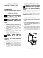
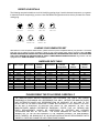
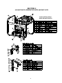
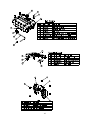
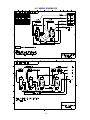
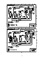
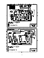
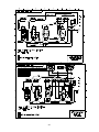
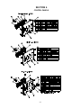
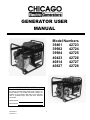
GENERATOR USER MANUAL Model Numbers 39461 42723 39982 42724 39984 42725 40423 42726 40814 42727 40827 42728 MODEL & SERIAL NUMBER Enter the Model and Serial numbers of your generator in the spaces provided below. Retain these numbers for future reference. The Model and Serial numbers are located on the generator data plate on the alternator case or generator frame, along with other important information. Model Number Serial Number DOCCHI0011 6/14/00 Rev. 1 1 LIMITED 1 YEAR WARRANTY STATEMENT Harbor Freight Tools makes every effort to assure that it's Chicago Electric products meet high quality and durability standards, and warrants that this product is free from defects in materials and workmanship for the following periods (from the date of purchase): For 1 year: All generator components. Note: If this product is used by a professional contractor, we warrant that this product is free from defects in materials and workmanship for a period of 90 days (from the date of purchase). This limited warranty does not cover components or assemblies manufactured by other companies, including, but not limited to: engine, alternator, receptacles, etc. Warranties for all items not manufactured by Harbor Freight Tools are covered under the warranties of the respective manufacturers of those products. This limited warranty extends only to the original purchaser of the product and is not assignable or transferable to any subsequent purchaser/end user. This warranty does not apply to damage to the product, or to injuries or death to persons or property due directly or indirectly to abnormal use, abnormal conditions, improper storage, misuse, neglect, abuse, accident, repairs or alterations outside our facilities, lack of maintenance, or other acts which are not the fault of Harbor Freight Tools. Any implied warranty of merchantability, or fitness for a particular purpose of use, shall be limited to the duration of the foregoing written warranty, otherwise, the foregoing warranty is the purchaser's sole and exclusive remedy and in lieu of all other warranties, express or implied. Harbor Freight Tools shall not be liable for incidental or consequential damages or a loss of anticipated benefits or profits resulting from the purchase or use of the product or arising from the breach of the warranty even if Harbor Freight Tools knew of the likelihood of such damages. Some states do not allow limitation of how long an implied warranty lasts, so the above limitation may not apply to you (the original purchaser). Some states do not allow the exclusion of incidental or consequential damages, so the above limitation or exclusions may not apply to you (the original purchaser). To take advantage of this warranty, the product or part must be returned to us with transportation charges prepaid. Proof of purchase date and an explanation of the complaint must accompany the merchandise. If our inspection verifies the defect, we will either repair or replace the product at our election, or we may elect to refund the purchase price if we cannot readily and quickly provide you with a replacement. We will return repaired products at our expense, but if we determine there is no defect, or that the defect resulted from causes not within the scope of our warranty, then you must bear the cost of storing, and returning the product. This warranty gives you specific legal rights and you may also have other rights which vary from state to state. Harbor Freight Tools 3491 Mission Oaks Blvd., P.O. Box 6009, Camarillo, CA 93011 Telephone Number: (800) 444-3353 2 Contents LIMITED 1 YEAR WARRANTY STATEMENT ................................................................................................. 2 SECTION 1........................................................................................................................................................ 4 GENERAL INFORMATION ............................................................................................................................. 4 SAFETY RULES.............................................................................................................................................. 4 BATTERY SAFET Y......................................................................................................................................... 4 GENERAL SAFETY OPERATIONAL GUIDELINES.......................................................................................... 5 GENERAL MAINTENANCE ............................................................................................................................ 6 GENERATOR CLEANING ............................................................................................................................... 6 GENERAL STORAGE GUIDELINES ................................................................................................................ 6 GENERAL BATTERY INSTALLATION ........................................................................................................... 6 ELECTRICAL LOADS AND GUIDELINES ....................................................................................................... 7 GENERATOR DESIGNED PERFORMANCE GUIDELINES ............................................................................... 7 ENGINE LIMITATIONS ON GENERATOR PERFORMANCE ............................................................................ 7 RECEPTACLE DETAILS ................................................................................................................................. 8 LOADING YOUR GENERATOR SET ............................................................................................................... 8 AMPERAGE RATE TABLE.............................................................................................................................. 8 SECTION 2........................................................................................................................................................ 9 40814/42723/42724 GENERATOR PARTS AND PART LISTS............................................................................. 9 A.C. Wiring Schematics................................................................................................................................ 12 SECTION 3...................................................................................................................................................... 14 39461/39982/40423/42725/42726/42727/39984/40827/42728 GENERATOR PARTS AND PART LIST................... 14 A.C. Wiring Schematics................................................................................................................................ 16 SECTION 4...................................................................................................................................................... 21 CONTROL PANELS ...................................................................................................................................... 21 3 SECTION 1 SERVICE OR REPAIR THIS GENERATOR UNLESS FULLY QUALIFIED TO DO SO. GENERAL INFORMATION This manual is provided for you so that your generator may be properly, safely and effectively applied and operated. Please read and understand all aspects of this manual before operating your generator set. Please also read and understand the documentation supplied with this generator regarding the engine. Keep this documentation in a safe and accessible place so that reference can be made as needed. All operators, users and subsequent owners of this generator must read and understand all aspects of this documentation before operation. DANGER: DO NOT OPERATE THIS GENERATOR IF THE AMBIENT TEMPATURE EXCEEDS 104ºF/40ºC. SAFETY RULES DANGER: This generator set is designed to be operated in dry conditions and for outdoor areas only. Never operate this generator indoors. Never operate this generator in rain, snow, sleet or generally wet conditions. Damage to the generator, bodily injury, or death could result from electrocution. SPARK ARRESTING MUFFLER DANGER: If this generator is connected to a building, home, business, or any other electrical circuit normally fed by utility power, steps must be taken to insure the generator output and the utility power are positively isolated. Failure to isolate the utility and generator electrical systems will result in generator damage and could result in injury or death to utility workers due to the backfeed of electricity. Certain States and Jurisdictions require that engine driven equipment be fitted with spark arresting mufflers. Depending on the generator model, spark arresting mufflers may or may not be fitted. If spark arresting mufflers are required for your specific local and the generator muffler is not spark arresting, contact your local dealer for instructions for a retrofit. CAUTION: Do not exceed the rated capacity of the generator. The total electrical loads at each outlet must be added to determine the total electrical load. The total load must not exceed the rated capacity of the generator. If the driven apparatus does not list wattage, but only amperage, wattage may be determined by multiplying amperage times voltage (watts = amps X volts). EXHAUST EMISSION CONTROL SYSTEM The exhaust emission control system for this generator complies to the standards set forth by the California Air Resources Board (CARB) and the Environmental Protection Agency (EPA). Warranties for the exhaust emission system are administered by the respective engine manufacturers. Refer to the engine documentation for warranty information. The engine exhaust from this product contains chemicals known to the State of California to cause cancer, birth defects, or other reproductive harm. CAUTION: Do not tamper with the enginegoverned speed. The generator operates at a nominal speed of 3600 rpm. Increases in speed over the 3600 rpm nominal will increase the chance of personal injury due to rotational stresses on the rotating members. Operation of the generator at speeds below the nominal 3600 rpm could cause damage to the generator or driven apparatus due to low voltage output. THIS SYMBOL IS USED THROUGHOUT YOUR OWNER’S MANUAL TO BRING ATTENTION TO IMPORTANT SAFETY INSTRUCTIONS. FAILURE TO FOLLOW SAFETY INSTRUCTIONS COULD ENDANGER YOU OR OTHERS AND RESULT IN PERSONAL INJURY OR DEATH. READ AND UNDERSTAND ALL SAFETY INSTRUCTIONS BEFORE OPERATION. CAUTION: Do not modify or misapply your generator set. Operation of the generator other than intended, could result in generator set damage, bodily injury or even death from electrocution. WARNING DO NOT OPERATE THIS GENERATOR WITHIN AN ENCLOSED AREA. THE EXHAUST GASES OF THIS GENERATOR EMIT “DEADLY” CARBON MONOXIDE. EXPOSURE TO CARBON MONOXIDE CAN CAUSE CARBON MONOXIDE POISONING, HEADACHES, NAUSEA, SEVERE SICKNESS OR DEATH. BATTERY SAFETY WARNING: STORAGE BATTERIES PRODUCE AND RELEASE EXPLOSIVE HYDROGEN GAS WHEN CHARGING. THE SLIGHTEST SPARK, FLAME OR BURNING ASH CAN IGNITE THESE GASES CAUSING A SERIOUS EXPLOSION THAT COULD RESULT IN BLINDNESS OR OTHER SERIOUS INJURIES. DANGER: THIS GENERATOR SET PRODUCES ELECTRICAL CURRENT. THEREFORE, SAFETY GUIDELINES MUST BE FOLLOWED. IMPROPER USE OF THIS GENERATOR CAN RESULT IN ELECTROCUTION, INJURY OR DEATH. DO NOT OPERATE, 4 WARNING: WEAR EYE PROTECTION, RUBBER APRON AND RUBBER GLOVES WHEN WORKING AROUND A BATTERY OR PERFORMING BATTERY SERVICE. BATTERY FLUID IS AN EXTREMELY CAUSTIC SULFURIC ACID, WHICH CAN CAUSE SEVERE BURNS. DO NOT PERMIT THE BATTERY FLUID TO COME IN CONTACT WITH YOUR CLOTHES OR SKIN. WARNING: ALWAYS DISCONNECT THE NEGATIVE (-) BATTERY CABLE FROM THE BATTERY BEFORE PERFORMING BATTERY SERVICE OR BEFORE PERFORMING ANY ELECTRICAL SERVICE ON THE GENERATOR OR ENGINE. GENERAL SAFETY OPERATIONAL GUIDELINES Read and understand all the general safety operational guidelines and rules before operating this generator. Always follow National and Local electrical codes. When moving or transporting this generator, take proper precautions to avoid fuel spillage. Further, always use common sense when lifting this generator. An adequate number of people and proper lifting procedures must be used. Do not wire your generator to a home or structure fed by utility power without proper isolation circuitry. Consult a local licensed electrician for proper wiring of your generator to a home, business or any facility or structure fed by utility power. Failure to properly isolate utility and generator electrical power could result in generator damage or electrocution to you or a utility worker. The main breaker, which disconnects from the utility power, must be open before the generator can safely be connected. Do not operate this generator unless the generator is in good mechanical and electrical condition. Do not overload this generator. Overloading this generator can cause generator damage, powered apparatus damage and excessive heat build up. Always keep hands, body parts, hair and clothing well away from the rotating or “HOT” parts of the generator set. Exhaust systems can cause severe burns. Do not start this generator with connected devices turned “ON”. Always make sure that connected devices are disconnected from the generator or turned “OFF” before starting the generator. Do not operate this generator within an enclosed area. The operation area of the generator must be completely open. The exhaust gases of this generator emit “DEADLY” carbon monoxide. Exposure to carbon monoxide can cause carbon monoxide poisoning, headaches, nausea, severe sickness or death. Do not install this generator in an enclosed area such as a RV or motorhome. All warranty will be null and void if installed within an enclosed area. Always insure that at least 6 feet of clearance on all sides of the generator are maintained during operation. Failure to maintain proper clearance 5 could damage your generator and potentially lead to fires. Never touch a receptacle or bare wire. Electrocution or shock could result. Gasoline is highly FLAMMABLE and its vapors are EXPLOSIVE. Handle gasoline with extreme care. Failure to properly handle gasoline can result in explosion or fire. Do not permit smoking within 50ft of this generator set. NEVER REFILL A HOT GENERATOR WITH FUEL. NEVER REFILL THE GENERATOR WHILE IT IS RUNNING. Spillage onto the engine or generator could result in an explosion or fire. Always allow the generator set to cool before refilling. Do not store this generator set in any location where gasoline fumes could potentially come into contact with sparks, a pilot light or an open flame. Improper storage of this generator could result in an explosion or fire. GROUNDING: The NATIONAL ELECTRICAL CODE requires that the generator frame be properly grounded to earth. A ground lug is provided on the generator frame. As a general guideline, a 10 AWG wire connected to the grounding lug of the generator on one end (located on the generator frame as indicated by the International “GROUND” symbol) and connected to a copper or brass ground rod (driven into the ground) on the other end of the wire. Some locations require generator set or other grounding. Check with a local electrician to determine the grounding requirements for your area. Electrical generators produce electricity. Therefore, never allow or perform service operations to your generator set without proper training/certification. Service operations, without proper precautions can cause severe shock and even death by electrocution. Generators operating on job or construction sites must be equipped with GFCI (Ground Fault Circuit Interrupters) on all circuits. Certain generator models are not equipped with GFCI circuits. Therefore, customer supplied GFCI’s must be installed in the power cords connected to the generator. Consult a local licensed electrician for proper wiring. Use only 3-Prong extension cords in good condition and make sure that the wire size within the extension cords is of sufficient size to safely carry the surge output of the generator. Never handle extension cords or electrical circuits if standing in water or if standing in a damp area. Operate, service or fill with fluids on a level surface only. Do not operate this generator in a corrosive or flammable environment. Never clean this generator with high-pressure water or a garden hose. Water can accumulate within the generator and cause fuel system, ignition system and or electrical problems or shorts. Cleaning should be done with a damp rag on a cool generator set. GENERAL BATTERY INSTALLATION GENERAL MAINTENANCE WARNING: DO NOT ATTEMPT TO OPERATE THE GENERATOR WITHOUT THE BATTERY INSTALLED UNLESS BOTH THE RED(+) AND BLACK(-) CABLE ENDS ARE COMPLETELY INSULATED OR THE CABLES ARE REMOVED ENTIRELY. ENGINE FUEL: Use Unleaded Fuel - ONLY! ENGINE OIL: documentation. Refer to the Engine related ENGINE MAINTENANCE: Refer to the documentation supplied regarding the engine for all engine maintenance issues. BATTERY SPECIFICATION: 145 CCA; INTERSTATE BATTERY Model SP-18 or Equivalent GENERATOR CLEANING With reference to the diagram below and to the safety guidelines that must be respected for handling batteries, install the battery as follows: CAUTION!: ALWAYS SHUT OFF THE GENERATOR AND ALLOW THE GENERATOR TO COMPLETELY COOL BEFORE PERFORMING CLEANING OPERATIONS. 1. 2. WARNING! DO NOT USE HIGH PRESSURE WATER OR A GARDEN HOSE TO CLEAN YOUR GENERATOR. WATER INTRODUCED INTO THE GENERATOR CAN CAUSE ELECTRICAL SHORTS, GENERATOR DAMAGE OR PERSONAL INJURY. 3. 4. Compressed air (max. 25 psi) may be used to blow loose dirt and dust from your generator. DO NOT DIRECT COMPRESSED AIR DIRECTLY INTO ANY OPENING IN THE GENERATOR OR ENGINE. Use a dampened cloth to wipe clean exterior surfaces. Use a soft bristle brush to clean/ loosen heavy dirt, oil or grease deposits. NEVER insert rags, tools or any device into the generator or engine openings. 5. 6. 7. Place the battery into the battery tray. Place the battery hold down bar (oriented as shown) on top of the battery. Install qty (2) battery hold down bolts and washers as shown. NOTE: Some versions require lock washers and nuts on lower side of battery tray. Gently and evenly tighten the battery hold down bolts. Do not crush and or deform the battery case in the tightening process. Insure that the engine key switch is in the “off” position. Connect the red (+) cable to the battery (+) terminal using the supplied bolt, washers and nut. Tighten the bolt. Connect the black (-) cable to the battery (-) terminal using the supplied bolt, washers and nut. Tighten the bolt. GENERAL STORAGE GUIDELINES WARNING: GASOLINE FUMES ARE FLAMMABLE. DO NOT STORE YOUR GENSET IN ANY AREA THAT IS INDOORS OR IN POORLY VENTILATED AREAS. GASOLINE FUMES CAN IGNITE IN THE PRESENCE OF ANY OPEN FLAME, PILOT LIGHT, CLOTHES DRYER, WATER HEATER, ETC. Your generator should be started and operated for several minutes at least every 30 days. If the generator cannot be operated every 30 days, follow the storage recommendations within the engine documentation. NOTE: A fuel shut-off valve is positioned at the base of the fuel tank. The valve should be closed during storage periods. Battery Installation Diagram 6 GENERATOR DESIGNED PERFORMANCE GUIDELINES ELECTRICAL LOADS AND GUIDELINES This electrical generator is designed to produce electrical energy for the purpose of powering lights, power tools, appliances and motor loads within the intended design constraints of the generator. The generator is designed to produce single-phase electrical power at 120 or 120/ 240 VAC. This generator is not intended for installation in RV or motorhome applications. The Performance Specifications for your generator are listed in Table 2 Performance Specifications. Your generator set is designed to power electrical apparatuses within the electrical power output limitations of the generator. Please note that any generator overload can cause serious problems/damage to your generator. Additionally, apparatuses with electrical motors can require higher wattage requirements at start-up than when running. Some electric motors require as much as 2.5 times the rated wattage at start-up. Although the start-up wattage requirements for electric motors lasts only a few seconds, great care must be taken in connecting loads to your generator so as not to overload the generator. Refer to the label on each electrical apparatus to determine the wattage requirements of that apparatus. THE TOTAL WATTAGE REQUIREMENTS OF ALL POWERED APPARATUSES (INCLUDING START-UP LOADS) MUST NEVER EXCEED THE CONTINUOUS RATING OF YOUR GENERATOR, CORRECTED TO THE ACTUAL ENVIRONMENTAL CONDITIONS AT THE OPERATING SITE. Table 2 SKU Number As a reference only, Table 1 below shows some general wattage requirements for several common electrical devices. This chart is intended as a guide only. The actual total wattage should be determined by referring to the actual labels on each of the powered electrical devices. Table 1 Item PERFORMANCE SPECIFICATIONS Voltage Cont. Watts Surge Watts 40814 42723 42724 39461 40423 42725 42726 39982 42727 120/240 VAC (Single Phase) 4400 Watts 37.5 Amps @ 120 VAC 18.5 Amps @ 240 VAC 6100 Watts 51 Amps @ 120 VAC 26 Amps @ 240 VAC 5000 Watts 42 Amps @ 120 VAC 21 Amps @ 240 VAC 8000 Watts 67 Amps @ 120 VAC 33 Amps @ 240 VAC 39984 40827 42728 120/240 VAC (Single Phase) 9350 Watts 78 Amps @ 120 VAC 39 Amps @ 240 VAC 10500 Watts 88 Amps @ 120 VAC 44 Amps @ 240 VAC 10000 Watts 83 Amps @ 120 VAC 41.5 Amps @ 240 VAC 12000 Watts 100 Amps @ 120 VAC 50 Amps @ 240 VAC 120/240 VAC (Single Phase) 120/240 VAC (Single Phase) Table 3 SKU Number 40814 42723 42724 39461 40423 42725 42726 39982 42727 39984 40827 42728 GENERAL WATTAGE GUIDE Running Watts Air Conditioner (12000 Btu) (*)........................ 1750 Air Compressor (1/2 hp) (*)............................ 1400 Air Compressor (3/4 hp) (*)............................ 1800 Air Compressor (1 hp) (*)............................... 2000 Battery Charger (25A).....................................600 Belt Sander (3” belt)...................................... 1000 Circle Saw (6 ½”) ...................................825-1050 Coffee Maker.........................................900-1100 Edger (lawn)..................................................550 Furnace Fan (1/3 hp) (*)................................ 1200 Hot Plate (single).......................................... 1500 Impact wrench ...............................................600 Light Bulb............................................ Bulb rated Nail Gun ..................................................... 1200 Microwave.....................................................750 Paint Sprayer (1/3 hp) (*).................................650 Paint Sprayer, hand-airless..............................175 Radio ...................................................... 50-200 Refrigerator (*)...............................................600 Table Saw (10”) (*) ....................................... 2000 Television............................................... 250-550 Weed Trimmer...............................................500 Note: (*) Items allow 2.5 times the listed wattage for starting. Engine Type Engine Honda GX 270 Honda GX 270 Honda GX 270 Honda GX 390 Honda GX 390 Honda GX 390 Honda GX 390 Vanguard Vanguard Vanguard Honda GX 620 Honda GX 620 HP 9.0hp 9.0hp 9.0hp 13.0hp 13.0hp 13.0hp 13.0hp 16.0hp 16.0hp 18.0hp 20.0hp 20.0hp ENGINE LIMITATIONS ON GENERATOR PERFORMANCE Generator ratings assume 60F (20C) and Sea Level. Operation of your generator at temperatures above 60F (20C) or above Sea Level will result in lower electrical output. Electrical output must be derated 2% for each 9F above 60F and 3 ½ % for each 1000 feet above mean sea level. 7 RECEPTACLE DETAILS The following receptacle details are to aid in identifying mating plugs. Use this chart and compare to your genset to determine which receptacle(s) you have. Note the NEMA configuration and use this to purchase the correct mating plug. NEMA 5-20R 125V - 20A NEMA L5-30R 125V - 30A NEMA L6-30R 250V - 30A NEMA 14-50R 125/250V - 50A NEMA L14-20R 125/250V - 20A NEMA L14-30R 125/250V - 30A NEMA L6-20R 250V - 20A LOADING YOUR GENERATOR SET With reference to the Receptacle details section, please review the power receptacles fitted to your generator. The actual load that may be pulled from each receptacle is driven by the circuit breaker rating and the generator rating. DO NOT EXCEED THE INDIVIDUAL RECEPTACLE RATINGS AS SHOWN IN THE AMPERAGE RATE TABLE. DO NOT EXCEED THE TOTAL GENERATOR RATING SHOWN IN TABLE 2 PERFORMANCE SPECIFICATIONS. All generator units are equipped with a “PUSH TO RESET” Circuit Breaker. AMPERAGE RATE TABLE Model/ SKU NEMA 5-20R 120V – Duplex 39461 39982 39984 40423 40814 40827 42723 42724 42725 42726 42727 42728 20Amps 15Amps 20Amps 20Amps 20Amps 20Amps 20Amps 20Amps 20Amps 20Amps 15Amps 20Amps NEMA L5-30R NEMA L14-30R 120V Twistlock 125V/250V Twistlock 30Amps 30Amps 30Amps 30Amps 30Amps 30Amps 30Amps 30Amps 20Amps N/A 30Amps 30Amps N/A 20Amps 20Amps N/A N/A 20Amps 30Amps 30Amps 30Amps 30Amps 30Amps 30Amps NEMA L6-30R 250V Twistlock 30Amps 25Amps 30Amps 30Amps 20Amps 30Amps N/A 20Amps N/A 30Amps 25Amps 30Amps NEMA 14-50R 125V/250V Straight Blade N/A 35Amps 40Amps N/A N/A 45Amps N/A N/A N/A N/A 35Amps 40Amps NEMA L6-20R 250V Twistlock N/A N/A N/A N/A 20Amps N/A N/A 20Amps N/A N/A N/A N/A NEMA L14-20R 125V/250V Twistlock N/A N/A N/A N/A 20Amps N/A 20Amps 20Amps 20Amps N/A N/A N/A PLEASE READ THE FOLLOWING CAREFULLY THE MANUFACTURER AND/OR DISTRIBUTOR HAS PROVIDED THE PARTS AND WIRING DIAGRAM(S) IN THIS MANUAL AS A REFERENCE TOOL ONLY. NIETHER THE MANUFACTURER NOR DISTRIBUTOR MAKES ANY REPRESENTATION OR WARRANTY OF ANY KIND TO THE BUYER THAT HE OR SHE IS QUALIFIED TO MAKE ANY REPAIRS TO THE PRODUCT OR THAT HE OR SHE IS QUALIFIED TO REPLACE ANY PARTS OF THE PRODUCT; IN FACT THE MANUFACTURER AND/OR DISTRIBUTOR EXPRESSLY STATES THAT ALL REPAIRS AND PARTS REPLACEMENTS SHOULD BE UNDERTAKEN BY CERTIFIED AND LICENSED TECHNICIANS AND NOT BY THE BUYER. THE BUYER ASSUMES ALL RISK AND LIABILITY ARISING OUT OF HIS OR HER REPAIRS TO THE ORIGINAL PRODUCT OR REPLACEMENT PARTS THERETO, OR ARISING OUT OF HIS OR HER INSTALLATION OF REPLACEMENT PARTS THERETO. PARTS MY CHANGE OR VARY FROM THOSE SHOWN. 8 SECTION 2 40814/42723/42724 GENERATOR PARTS AND PART LISTS Frame and Parts list for SKU # 40814/42723/42724 9 10 11 A.C. WIRING SCHEMATICS 12 13 SECTION 3 39461/39982/40423/42725/42726/42727/39984/40827/42728 GENERATOR PARTS AND PART LIST Frame and Parts list for SKU # 39461/39982/40423/ 42725/42726/42727/39984/40827/ 42728 For Items 9, 12, and 13 please refer to Section 2 of this manual. 14 15 A.C. WIRING SCHEMATICS 16 17 18 19 20 SECTION 4 CONTROL PANELS 21 22 NOTES 23