1
User’s Guide
© 2007 Ricoh Corporation
5 Dedrick Place
West Caldwell, NJ 07006
January 2007
N905363B
© 2007 Ricoh Corporation. All rights reserved.
No part of this document may be reproduced without the expressed permission of Ricoh
Corporation.
The material in this document is for informational purposes and is subject to change
without notice. Ricoh Corporation assumes no responsibility for errors or omissions in
this document. No liability is assumed for any damages resulting from the use of the
information it contains.
TRADEMARK
Adobe and Postscript are registered trademarks of Adobe Systems Incorporated. PCL
is the trademark of Hewlett Packard. Ethernet is a trademark of Xerox Corporation.
Windows XP is a trademark of Microsoft Corporation. Digital Document Publisher and
DDP and its associated logo mark are the trademarks of Ricoh Corporation. Ricoh and
the Ricoh trademark are registered trademarks of Ricoh, Ltd. All rights reserved.
All other terms and product names may be trademarks or registered trademarks of their
respective owners and are hereby acknowledged.
NOTICE TO USER
In an effort to meet the demands of a rapidly changing technology, the manufacturer is
continually developing new features and functions to meet changing printing or printer
needs. Please be sure to consult all manual updates or addenda when using this
product’s documentation.
This document contains TrueType fonts from Monotype Imaging Inc. Reproduction of
these fonts is prohibited.
The software embedded in this product is based in part on the work of Independent
JPEG Group.
The software embedded in this product uses software by CMU. Copyright 1988, 1989
by Carnegie Mellon University. All rights reserved.
Permission to use, copy, modify, distribute and sell this software and its documentation
for any purpose and without fee is hereby granted, provided that the avove copyright
notice appears in all copies and that both the copyright notice and permission notice
appear in supporting documentation, and the name of CMU not be used in advertising
or publicity pertaining to distribution of the software without specific written prior
permission.
The software embedded in this product uses the software by Sam Leffler and Silicon
Graphics.
Copyright (c) 1988-1997 Sam Leffler
Copyright (c) 1991-1997 Silicon Graphics, Inc
Permission to use, copy, modify, distribute and sell this software and its documentation
for any purpose and without fee is hereby granted, provided that the above copyright
notice appear in all copies of the software and related documentation, and (ii) the names
of Sam Leffler and Silicon Graphics may not be used in advertising or publicity pertaining
to distribution of the software without specific, written prior permission of Sam Leffler and
Silicon Graphics.
Rev. Table
Rev. for
Manual
Machine
Rev.
Page No. (Contents)
Date
00
-
First Edition
Jul. 21, 2005
01
-
vi, 2-11, 2-12, 2-14, 2-16, 2-17, 2-20 - 2-22, 3-3, 3-5 - 3-30, 6-2,
6-5 - 6-41
Sep. 15, 2005
02
-
v(01), vi(02), viii(01) : Some headings and Page No. are modified.
Nov. 17, 2005
Safety Summary-2(01) ~ Safety Summary-4(01) :
Some WARNING statements and CAUTION statements are
modified.
2-7(01) : Figure is changed.
2-11(02) : Figure is changed, and “Paper Color” is added.
2-12(02) : “HCF Tray Control” is added.
2-13(01), 2-14(02) : Contents are moved from previous page.
2-15(01) : “PCL” is added.
2-16(02) : Contents are moved from previous page.
2-17(02) : “Paper Color” is added.
2-18(01) : “HCF Tray Control” and “PCL” are added.
2-19(01) : Figure is corrected.
2-20(02) : Contents are moved from previous page.
2-21(02), 2-22(02) : “Language” is changed.
2-23(01) : Figure is changed, and “Configuration” is added.
2-24(01), 2-25(01) : Contents are moved from previous page.
2-26(01) : Page is added.
3-1(01), 3-3(02):
Title is changed to “Paper Size, Paper Weights, Paper Types and
Paper Color”.
3-5(02) : “Tracing Paper” is added.
3-6(02) : “Paper Color” is added.
3-7(02) ~ 3-30(02) : Contents are moved from previous page.
4-11(01) ~ 4-15(01) : Figure number is changed.
4-33(01) ~ 4-36(01) :
Procedure of step 8 ~ step 13 is modified, and a caution is added.
4-37(01) ~ 4-41(01) : Step number is changed.
4-42(01) ~ 4-59(01) : Contents are moved from previous page.
4-60(01) : Page is added.
5-7(01) : Add the notation for the HCF Tray Control.
6-2(02) : Language is changed.
Rev. Table
Rev. for
Manual
02
Machine
Rev.
-
Page No. (Contents)
6-4(01) : Figure is changed.
Date
Nov. 17, 2005
6-5(02) : Language is changed, and Figure is changed.
6-6(02) : Figure is changed.
6-7(02) : “Error Information” is deleted.
6-8(02) : Contents of “Tray” is changed.
6-9(02) ~ 6-17(02) : Figure is changed.
6-18(02) : Contents of “Tray” is changed.
6-19(02) ~ 6-21(02) : Figure is changed, and explanation is modified.
6-22(02) : Explanation is added.
6-23(02), 6-24(02) : Figure is changed.
6-25(02) : Figure is changed, and explanation is modified.
6-26(02) ~ 6-28(02) : Figure is changed.
6-29(02), 6-30(02) : Figure is changed, and explanation is added.
6-31(02) : Explanation is added.
6-32(02) ~ 6-36(02) : Figure is changed, and explanation is added.
6-37(02) ~ 6-39(02) : Figure is changed.
6-40(02) : Contents are moved from previous page.
6-41(02) ~ 6-43(02) : Figure is changed.
6-44(02), 6-45(02) : Figure is changed, and explanation is added.
6-46(02), 6-47(01) : Figure is changed, and explanation is modified.
6-48(01) : Figure is changed, and explanation is added.
6-49(01) : Explanation is added.
6-50(01) : Figure is changed.
6-51(01), 6-52(01) : Figure is changed, and explanation is added.
6-53(01) ~ 6-56(01) : Contents are moved from previous page.
03
-
TOC-1(02), TOC-2(03), TOC-3(01), TOC-4(02) :
Page Number of Table of Contents are changed.
Some headings and Page No. are modified.
Safety Summary-12(01) : Caution Plates are changed.
1-5(01) : Figure 1-2 is changed.
4-17(01) ~ 4-19(01) : Figures are changed.
4-31(01) : Figure 4-56 is changed.
4-33(02) : Figure and CAUTION statement are changed.
4-34(02) ~ 4-36(02) : Figures are changed.
4-51(02) : Add the cleaning items, and correct the misentry.
Feb. 4, 2006
Rev. Table
Rev. for
Manual
03
Machine
Rev.
-
Page No. (Contents)
4-55(02) : Figure 4-110 is changed, and misentries are corrected.
Date
Feb. 4, 2006
4-56(02), 4-57(02) : Misentries are corrected.
4-58(02), 4-59(02) : All contents of “Cleaning the paper guide of the
Fuser Unit” are added.
4-60(02), 4-61(02) : All contents of “Cleaning the paper guide of the
Discharger Unit” are added.
4-62(01) ~ 4-64(01) : Contents are moved from previous page.
04
-
TOC-1(03), TOC-2(04), TOC-3(02), TOC-4(03):
Some page number are modified.
Safety Summary-3(02), Safety Summary-4(02) :
Some caution statements are added.
SafetySummary-7(01) :
All contents are added.
SafetySummary-8(01) ~ SafetySummary-13(01) :
Contents are moved from previous page.
SafetySummary-14(01): Page is added.
1-9(01) : Caution statement is added.
2-6(01) : NOTE statement is added.
2-7(02) : Fugire 2-5 is changed.
2-10(01) : Network name is changed.
2-14(03) : “Exit Jam Recovery” is deleted.
“LPD Queuing” is modified.
2-16(03) : “Paper Size” is modified.
2-17(03) : “Paper Color” is modified.
2-18(02) : “Exit Jam Recovery” is deleted.
2-19(02) : NOTE Statement is added.
2-20(03) : Network name is changed.
“Exit Jam Recovery” is added.
2-21(03) : “Auto Online”, “Auto Backup Time” and “Output
Cascade” are added.
2-22(03) : Contents are moved from previous page.
2-23(03) : Network name is cahnged.
“Exit Jam Recovery”, “Auto Online”, “Auto Backup
Time” and “Output Cascade” are added.
“Note 8” is added.
2-24(02) ~ 2-26(02) : Contents are moved from previous page.
3-3(03) : “Letter Tab Stock “ and “A4 Tab Stock” are added.
3-6(03) : Custom color number is changed from 16 to 80.
3-14(03) : Contents are modified.
Mar. 22, 2006
Rev. Table
Rev. for
Manual
04
Machine
Rev.
-
Page No. (Contents)
3-15(03) : All contents are added.
3-16(03) : Figure 3-13 is changed.
3-17(03) : Figure 3-15, 3-16 are changed.
3-18(03) ~ 3-31(01) : Contents are moved from previous page.
3-32(01) : Page is added.
5-8(01) : Some statements are added.
5-9(01) : Contents are moved from previous page.
Table Number is changed.
5-10(01) : Contents are moved from previous page.
Corective action of “Insufficient Disk Space”
is modified.
5-24(01) : CAUTION Statement is added.
6-15(03) : Figure 6-12 is changed.
Network name is changed.
6-17(03) : Figure 6-14 is changed.
6-24(03) : Figure 6-19 is changed.
Custom color number is changed from 16 to 80.
6-28(03) : Contents are modified.
6-29(03) : “LPD Banner Page” is modified.
6-30(03) : Figure 6-25 is modified.
Contents of each option are modified.
6-31(03) : Contents of each option are modified.
“Paper Color”, “Rotation”, “Reverse Order” and “Job
Partial Page Print” are added.
6-33(03) : Figure 6-27 is changed.
“Paper Color” is deleted.
6-44(03) : Figure 6-38 is changed.
Contents of each option are modified.
“Auto Online” and “Output Cascade - ...” are added.
6-45(03) : “Use Time Server” is modified.
6-48(02) : Figure 6-42 is changed.
Network name is changed.
6-49(02) : “Host Name” and “DNS Server Address” are added.
6-50(02) ~ 6-52(02) : Figures are cahnged.
Network name is changed.
6-56(01) ~ 6-59(01) : All contents are added.
6-60(01) : Blank page is added.
Date
Mar. 22, 2006
Rev. Table
Rev. for
Manual
05
Machine
Rev.
-
Page No. (Contents)
Cover sheet : “Reed and keep this manual” is added.
Back of cover sheet : “TRADEMARK” is added.
“NOTICE TO USER” is modified.
TOC-2(05) ~ TOC-4(04) : Some headings and Page No. are
modified.
1-4(01) : Transit Pass Unit Type 156 is added.
1-10(01) : Figure 1-9 is changed.
2-10(02) : “Usage - Click Charge Counter” is added.
2-14(04) : “Cover Insert Mode” is added.
2-16(04) : “Letter TAB LEF” and “A4 TAB LEF” are deleted.
2-18(03) : “Paper Output - Default Output” is modified.
“Options - Cover Insert Mode” is added.
3-3(04) : “Letter Tab Stock” and “A4 Tab Stock” are deleted.
3-14(04) : Table 3-4 and NOTE statement are modified.
3-15(04) : “Loading Tab Stock Paper” is deleted.
3-16(04) : Figure3-15 and 3-16 are changed.
3-17(04) ~ 3-30(04) : Pages are shifted.
3-31, 3-32 : Pages are deleted.
4-24(01) : Figure4-40 and Figure4-41 are changed.
4-27(01) : Figure4-46 is changed.
4-29(01) : Figure4-51 is changed.
4-31(02) : Figure4-55 is changed.
4-42(02) : Figure4-83 is changed.
4-48(02) : Figure4-98 is changed.
4-51(03), 4-52(02) : All contents are added.
4-53(02) : Interval of “Discharger, Detach Corotoron” is modified.
4-54(02) ~ 4-66(01) : Contents are moved from previous page.
5-8(02) : Some notations are modified.
5-12(02) : Error code “E011” is added.
5-13(02) : Some contents are shifted.
5-14(02) : Error codes “E064”, “E065” and “E067” are added.
5-15(02) : Some contents are shifted.
5-16(02) : Error Codes “E0B2” and “E0B3” are added.
5-17(02) : Error code “E0D0” is added.
5-18(02) ~ 5-23(02) : Some contents are shifted.
Date
Sep. 21, 2006
Rev. Table
Rev. for
Manual
05
Machine
Rev.
-
Page No. (Contents)
5-24(02) : Error codes “E1E0”, “E1E1”, “E1E2” and “E1E3” are
added
6-8(03) : “Click Charge Counter” is added to “Usage”.
6-9(03), 6-11(03) : Figure and contents are modified for Post Device.
6-14(03) : Figure 6-11 and contents are modified.
6-31(04) : “Paper Output” is modified.
6-44(04) : Figure 6-38 is changed.
“Cover Insert Mode” is added.
Date
Sep. 21, 2006
Table of Contents
SAFETY SUMMARY . . . . . . . . . . . . . . . . . . . . . . . . . . . . . . . . . . . . . .Safety Summary-1
Introduction
About This Manual . . . . . . . . . . . . . . . . . . . . . . . . . . . . . . . . . . . . . . . . . . . . . . . . . . . . . . . . . . 0-1
Audience . . . . . . . . . . . . . . . . . . . . . . . . . . . . . . . . . . . . . . . . . . . . . . . . . . . . . . . . . . . . . . 0-1
Manual Conventions . . . . . . . . . . . . . . . . . . . . . . . . . . . . . . . . . . . . . . . . . . . . . . . . . . . . . 0-2
For More Information . . . . . . . . . . . . . . . . . . . . . . . . . . . . . . . . . . . . . . . . . . . . . . . . . . . . 0-2
Chapter 1. Printer Overview
What This Chapter Provides . . . . . . . . . . . . . . . . . . . . . . . . . . . . . . . . . . . . . . . . . . . . . . . . . . . 1-1
Printer Features . . . . . . . . . . . . . . . . . . . . . . . . . . . . . . . . . . . . . . . . . . . . . . . . . . . . . . . . . . . . . 1-2
I/O Configurations . . . . . . . . . . . . . . . . . . . . . . . . . . . . . . . . . . . . . . . . . . . . . . . . . . . . . . . 1-3
Operator Control Panel . . . . . . . . . . . . . . . . . . . . . . . . . . . . . . . . . . . . . . . . . . . . . . . . . . . 1-3
External View of the Printer . . . . . . . . . . . . . . . . . . . . . . . . . . . . . . . . . . . . . . . . . . . . . . . . . . . 1-4
Internal View of the Printer. . . . . . . . . . . . . . . . . . . . . . . . . . . . . . . . . . . . . . . . . . . . . . . . . . . . 1-5
Powering On the Printer . . . . . . . . . . . . . . . . . . . . . . . . . . . . . . . . . . . . . . . . . . . . . . . . . . . . . . 1-6
Powering Off the Printer . . . . . . . . . . . . . . . . . . . . . . . . . . . . . . . . . . . . . . . . . . . . . . . . . . . . . . 1-7
Clearing Error Conditions . . . . . . . . . . . . . . . . . . . . . . . . . . . . . . . . . . . . . . . . . . . . . . . . . 1-8
Space Required for Installation. . . . . . . . . . . . . . . . . . . . . . . . . . . . . . . . . . . . . . . . . . . . . . . . 1-10
Chapter 2. Control Panels
What This Chapter Provides . . . . . . . . . . . . . . . . . . . . . . . . . . . . . . . . . . . . . . . . . . . . . . . . . . . 2-1
Description of Control Panels . . . . . . . . . . . . . . . . . . . . . . . . . . . . . . . . . . . . . . . . . . . . . . . . . . 2-2
OCP Menu Icons and Buttons. . . . . . . . . . . . . . . . . . . . . . . . . . . . . . . . . . . . . . . . . . . . . . . . . . 2-3
Using the OCP Menus. . . . . . . . . . . . . . . . . . . . . . . . . . . . . . . . . . . . . . . . . . . . . . . . . . . . . . . . 2-4
Using the Option Button Menu . . . . . . . . . . . . . . . . . . . . . . . . . . . . . . . . . . . . . . . . . . . . . 2-4
Using the Ten Key Pad Menu. . . . . . . . . . . . . . . . . . . . . . . . . . . . . . . . . . . . . . . . . . . . . . . 2-5
Using the + / - Change Button Menu . . . . . . . . . . . . . . . . . . . . . . . . . . . . . . . . . . . . . . . . . 2-6
Using the Enable/Disable Change Button Menu . . . . . . . . . . . . . . . . . . . . . . . . . . . . . . . . 2-7
OCP Menu Structure . . . . . . . . . . . . . . . . . . . . . . . . . . . . . . . . . . . . . . . . . . . . . . . . . . . . . . . . . 2-8
Main Menu . . . . . . . . . . . . . . . . . . . . . . . . . . . . . . . . . . . . . . . . . . . . . . . . . . . . . . . . . . . . . 2-8
Information Menu. . . . . . . . . . . . . . . . . . . . . . . . . . . . . . . . . . . . . . . . . . . . . . . . . . . . . . . . 2-9
Printer Menu . . . . . . . . . . . . . . . . . . . . . . . . . . . . . . . . . . . . . . . . . . . . . . . . . . . . . . . . . . . 2-11
Setup Menu. . . . . . . . . . . . . . . . . . . . . . . . . . . . . . . . . . . . . . . . . . . . . . . . . . . . . . . . . . . . 2-19
Reports Menu . . . . . . . . . . . . . . . . . . . . . . . . . . . . . . . . . . . . . . . . . . . . . . . . . . . . . . . . . . 2-24
Jobs Menu. . . . . . . . . . . . . . . . . . . . . . . . . . . . . . . . . . . . . . . . . . . . . . . . . . . . . . . . . . . . . 2-25
Sub Panel. . . . . . . . . . . . . . . . . . . . . . . . . . . . . . . . . . . . . . . . . . . . . . . . . . . . . . . . . . . . . . . . . 2-26
Table of Contents
OG
L
03
TOC-1
Chapter 3. Paper Handling
What This Chapter Provides . . . . . . . . . . . . . . . . . . . . . . . . . . . . . . . . . . . . . . . . . . . . . . . . . . . 3-1
Paper . . . . . . . . . . . . . . . . . . . . . . . . . . . . . . . . . . . . . . . . . . . . . . . . . . . . . . . . . . . . . . . . . . . . . 3-2
Unacceptable Paper . . . . . . . . . . . . . . . . . . . . . . . . . . . . . . . . . . . . . . . . . . . . . . . . . . . . . . 3-2
Storing Paper . . . . . . . . . . . . . . . . . . . . . . . . . . . . . . . . . . . . . . . . . . . . . . . . . . . . . . . . . . . 3-2
Paper Sizes, Paper Weights, Paper Types and Paper Color . . . . . . . . . . . . . . . . . . . . . . . . . . . 3-3
Paper Size . . . . . . . . . . . . . . . . . . . . . . . . . . . . . . . . . . . . . . . . . . . . . . . . . . . . . . . . . . . . . . 3-3
Paper Size Indication . . . . . . . . . . . . . . . . . . . . . . . . . . . . . . . . . . . . . . . . . . . . . . . . . . . . . 3-4
Paper Weights. . . . . . . . . . . . . . . . . . . . . . . . . . . . . . . . . . . . . . . . . . . . . . . . . . . . . . . . . . . 3-5
Paper Type . . . . . . . . . . . . . . . . . . . . . . . . . . . . . . . . . . . . . . . . . . . . . . . . . . . . . . . . . . . . . 3-5
Loading Paper . . . . . . . . . . . . . . . . . . . . . . . . . . . . . . . . . . . . . . . . . . . . . . . . . . . . . . . . . . . . . . 3-7
Proper Paper Handling . . . . . . . . . . . . . . . . . . . . . . . . . . . . . . . . . . . . . . . . . . . . . . . . . . . . 3-7
Loading Paper in Tray . . . . . . . . . . . . . . . . . . . . . . . . . . . . . . . . . . . . . . . . . . . . . . . . . . . . 3-9
Loading Special Media. . . . . . . . . . . . . . . . . . . . . . . . . . . . . . . . . . . . . . . . . . . . . . . . . . . . 3-6
Setting the Non-Standard Paper Size . . . . . . . . . . . . . . . . . . . . . . . . . . . . . . . . . . . . . . . . . . . 3-15
Setting the Paper Weight Value . . . . . . . . . . . . . . . . . . . . . . . . . . . . . . . . . . . . . . . . . . . . . . . 3-19
Setting the HV Adjust Values . . . . . . . . . . . . . . . . . . . . . . . . . . . . . . . . . . . . . . . . . . . . . . . . . 3-21
Setting the Table Adjust . . . . . . . . . . . . . . . . . . . . . . . . . . . . . . . . . . . . . . . . . . . . . . . . . . . . . 3-23
Setting the Paper Moisture . . . . . . . . . . . . . . . . . . . . . . . . . . . . . . . . . . . . . . . . . . . . . . . . . . . 3-25
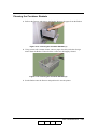
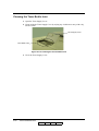
Preparing the Stacker . . . . . . . . . . . . . . . . . . . . . . . . . . . . . . . . . . . . . . . . . . . . . . . . . . . . . . . 3-27
Set the Basket into the Stacker . . . . . . . . . . . . . . . . . . . . . . . . . . . . . . . . . . . . . . . . . . . . . 3-27
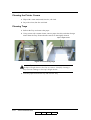
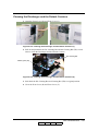
Removing Paper . . . . . . . . . . . . . . . . . . . . . . . . . . . . . . . . . . . . . . . . . . . . . . . . . . . . . . . . . . . 3-28
Removing Paper from the Stacker . . . . . . . . . . . . . . . . . . . . . . . . . . . . . . . . . . . . . . . . . . 3-28
Chapter 4. Care and Maintenance
What This Chapter Provides . . . . . . . . . . . . . . . . . . . . . . . . . . . . . . . . . . . . . . . . . . . . . . . . . . . 4-1
Replacing Consumables . . . . . . . . . . . . . . . . . . . . . . . . . . . . . . . . . . . . . . . . . . . . . . . . . . . . . . 4-2
Adding Toner . . . . . . . . . . . . . . . . . . . . . . . . . . . . . . . . . . . . . . . . . . . . . . . . . . . . . . . . . . . 4-2
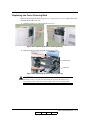
Replacing the Toner Bag . . . . . . . . . . . . . . . . . . . . . . . . . . . . . . . . . . . . . . . . . . . . . . . . . . 4-7
Replacing the Developer Mix . . . . . . . . . . . . . . . . . . . . . . . . . . . . . . . . . . . . . . . . . . . . . . 4-9
Replacing the Fuser Cleaning Web . . . . . . . . . . . . . . . . . . . . . . . . . . . . . . . . . . . . . . . . . 4-17
Replacing the Fine Filter . . . . . . . . . . . . . . . . . . . . . . . . . . . . . . . . . . . . . . . . . . . . . . . . . 4-20
Winding the OPC Sheet . . . . . . . . . . . . . . . . . . . . . . . . . . . . . . . . . . . . . . . . . . . . . . . . . . 4-22
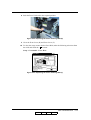
Clearing Paper Jams . . . . . . . . . . . . . . . . . . . . . . . . . . . . . . . . . . . . . . . . . . . . . . . . . . . . . . . . 4-24
Regist Cover . . . . . . . . . . . . . . . . . . . . . . . . . . . . . . . . . . . . . . . . . . . . . . . . . . . . . . . . . . 4-25
Input Station Area. . . . . . . . . . . . . . . . . . . . . . . . . . . . . . . . . . . . . . . . . . . . . . . . . . . . . . . 4-27
Regist Station Area . . . . . . . . . . . . . . . . . . . . . . . . . . . . . . . . . . . . . . . . . . . . . . . . . . . . . 4-29
Paper Feed Area . . . . . . . . . . . . . . . . . . . . . . . . . . . . . . . . . . . . . . . . . . . . . . . . . . . . . . . . 4-31
Container Stacker . . . . . . . . . . . . . . . . . . . . . . . . . . . . . . . . . . . . . . . . . . . . . . . . . . . . . . 4-42
High Capacity Feeder (HCF) . . . . . . . . . . . . . . . . . . . . . . . . . . . . . . . . . . . . . . . . . . . . . . 4-48
Transit Pass Unit Type 156 . . . . . . . . . . . . . . . . . . . . . . . . . . . . . . . . . . . . . . . . . . . . . . . 4-51
Cleaning the Printer. . . . . . . . . . . . . . . . . . . . . . . . . . . . . . . . . . . . . . . . . . . . . . . . . . . . . . . . . 4-53
Cleaning the Printer Covers . . . . . . . . . . . . . . . . . . . . . . . . . . . . . . . . . . . . . . . . . . . . . . . 4-54
Cleaning Trays . . . . . . . . . . . . . . . . . . . . . . . . . . . . . . . . . . . . . . . . . . . . . . . . . . . . . . . . . 4-54
Cleaning the Container Baskets . . . . . . . . . . . . . . . . . . . . . . . . . . . . . . . . . . . . . . . . . . . . 4-55
Cleaning the Toner Bottle Joint . . . . . . . . . . . . . . . . . . . . . . . . . . . . . . . . . . . . . . . . . . . . 4-56
TOC-2
Table of Contents
OG
L
05
Cleaning the Discharger and the Detach Corotron. . . . . . . . . . . . . . . . . . . . . . . . . . . . . . 4-57
Clearing the Inverter Valve Piece. . . . . . . . . . . . . . . . . . . . . . . . . . . . . . . . . . . . . . . . . . . 4-58
Cleaning the paper guide of the Fuser Unit . . . . . . . . . . . . . . . . . . . . . . . . . . . . . . . . . . . 4-60
Cleaning the paper guide of the Discharger Unit . . . . . . . . . . . . . . . . . . . . . . . . . . . . . . . 4-62
Handling and Storing Supplies and Consumables . . . . . . . . . . . . . . . . . . . . . . . . . . . . . . . . . 4-64
Paper . . . . . . . . . . . . . . . . . . . . . . . . . . . . . . . . . . . . . . . . . . . . . . . . . . . . . . . . . . . . . . . . 4-64
Toner and Developer . . . . . . . . . . . . . . . . . . . . . . . . . . . . . . . . . . . . . . . . . . . . . . . . . . . . 4-65
Chapter 5. Troubleshooting
What This Chapter Provides . . . . . . . . . . . . . . . . . . . . . . . . . . . . . . . . . . . . . . . . . . . . . . . . . . . 5-1
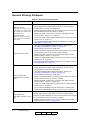
Guidelines Flowchart . . . . . . . . . . . . . . . . . . . . . . . . . . . . . . . . . . . . . . . . . . . . . . . . . . . . . . . . 5-2
Basic Troubleshooting Tips . . . . . . . . . . . . . . . . . . . . . . . . . . . . . . . . . . . . . . . . . . . . . . . . . . . 5-3
General Printing Problems . . . . . . . . . . . . . . . . . . . . . . . . . . . . . . . . . . . . . . . . . . . . . . . . . . . . 5-4
Print Quality Problems . . . . . . . . . . . . . . . . . . . . . . . . . . . . . . . . . . . . . . . . . . . . . . . . . . . . . . . 5-6
Duplex Printing Problems . . . . . . . . . . . . . . . . . . . . . . . . . . . . . . . . . . . . . . . . . . . . . . . . . . . . . 5-6
Printer Notice . . . . . . . . . . . . . . . . . . . . . . . . . . . . . . . . . . . . . . . . . . . . . . . . . . . . . . . . . . . . . . 5-7
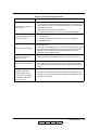
OCP Display Messages . . . . . . . . . . . . . . . . . . . . . . . . . . . . . . . . . . . . . . . . . . . . . . . . . . . . . . . 5-9
Printer Status Message . . . . . . . . . . . . . . . . . . . . . . . . . . . . . . . . . . . . . . . . . . . . . . . . . . . . 5-9
Printer Warning Message . . . . . . . . . . . . . . . . . . . . . . . . . . . . . . . . . . . . . . . . . . . . . . . . . 5-11
Printer Error Message. . . . . . . . . . . . . . . . . . . . . . . . . . . . . . . . . . . . . . . . . . . . . . . . . . . . 5-11
Chapter 6. Web Utilities
What This Chapter Provides . . . . . . . . . . . . . . . . . . . . . . . . . . . . . . . . . . . . . . . . . . . . . . . . . . . 6-1
Overview . . . . . . . . . . . . . . . . . . . . . . . . . . . . . . . . . . . . . . . . . . . . . . . . . . . . . . . . . . . . . . . . . . 6-1
Access and Security . . . . . . . . . . . . . . . . . . . . . . . . . . . . . . . . . . . . . . . . . . . . . . . . . . . . . . 6-3
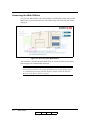
Accessing the Web Utilities . . . . . . . . . . . . . . . . . . . . . . . . . . . . . . . . . . . . . . . . . . . . . . . . 6-4
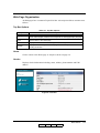
Web Page Organization . . . . . . . . . . . . . . . . . . . . . . . . . . . . . . . . . . . . . . . . . . . . . . . . . . . 6-5
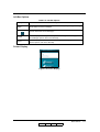
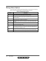
Manage Status Options . . . . . . . . . . . . . . . . . . . . . . . . . . . . . . . . . . . . . . . . . . . . . . . . . . . . . . . 6-8
Status-General . . . . . . . . . . . . . . . . . . . . . . . . . . . . . . . . . . . . . . . . . . . . . . . . . . . . . . . . . . 6-9
Status-Tray . . . . . . . . . . . . . . . . . . . . . . . . . . . . . . . . . . . . . . . . . . . . . . . . . . . . . . . . . . . . 6-10
Status-Paper Output . . . . . . . . . . . . . . . . . . . . . . . . . . . . . . . . . . . . . . . . . . . . . . . . . . . . . 6-11
Status-Consumables . . . . . . . . . . . . . . . . . . . . . . . . . . . . . . . . . . . . . . . . . . . . . . . . . . . . . 6-12
Status-Errors . . . . . . . . . . . . . . . . . . . . . . . . . . . . . . . . . . . . . . . . . . . . . . . . . . . . . . . . . . . 6-13
Status-Usage . . . . . . . . . . . . . . . . . . . . . . . . . . . . . . . . . . . . . . . . . . . . . . . . . . . . . . . . . . . 6-14
Status-Network . . . . . . . . . . . . . . . . . . . . . . . . . . . . . . . . . . . . . . . . . . . . . . . . . . . . . . . . . 6-15
Status-Report . . . . . . . . . . . . . . . . . . . . . . . . . . . . . . . . . . . . . . . . . . . . . . . . . . . . . . . . . . 6-16
Status-Revision. . . . . . . . . . . . . . . . . . . . . . . . . . . . . . . . . . . . . . . . . . . . . . . . . . . . . . . . . 6-17
Manage System Options . . . . . . . . . . . . . . . . . . . . . . . . . . . . . . . . . . . . . . . . . . . . . . . . . . . . . 6-18
System-General . . . . . . . . . . . . . . . . . . . . . . . . . . . . . . . . . . . . . . . . . . . . . . . . . . . . . . . . 6-19
System-Tray . . . . . . . . . . . . . . . . . . . . . . . . . . . . . . . . . . . . . . . . . . . . . . . . . . . . . . . . . . . 6-21
System-Paper Output . . . . . . . . . . . . . . . . . . . . . . . . . . . . . . . . . . . . . . . . . . . . . . . . . . . . 6-26
System-Virtual Printer . . . . . . . . . . . . . . . . . . . . . . . . . . . . . . . . . . . . . . . . . . . . . . . . . . . 6-27
System-Accounting . . . . . . . . . . . . . . . . . . . . . . . . . . . . . . . . . . . . . . . . . . . . . . . . . . . . . 6-37
System-Jobs . . . . . . . . . . . . . . . . . . . . . . . . . . . . . . . . . . . . . . . . . . . . . . . . . . . . . . . . . . . 6-38
System-Serial Number . . . . . . . . . . . . . . . . . . . . . . . . . . . . . . . . . . . . . . . . . . . . . . . . . . . 6-39
Manage Configuration Options. . . . . . . . . . . . . . . . . . . . . . . . . . . . . . . . . . . . . . . . . . . . . . . . 6-40
Table of Contents
OG
L
03
TOC-3
Configuration-General . . . . . . . . . . . . . . . . . . . . . . . . . . . . . . . . . . . . . . . . . . . . . . . . . . . 6-41
Configuration-Events . . . . . . . . . . . . . . . . . . . . . . . . . . . . . . . . . . . . . . . . . . . . . . . . . . . . 6-42
Configuration-Configuration . . . . . . . . . . . . . . . . . . . . . . . . . . . . . . . . . . . . . . . . . . . . . . 6-43
Configuration-Communication. . . . . . . . . . . . . . . . . . . . . . . . . . . . . . . . . . . . . . . . . . . . . 6-48
Using the Accounting File . . . . . . . . . . . . . . . . . . . . . . . . . . . . . . . . . . . . . . . . . . . . . . . . . . . 6-53
Accounting Slip Sheet. . . . . . . . . . . . . . . . . . . . . . . . . . . . . . . . . . . . . . . . . . . . . . . . . . . . . . . 6-56
Appendix A. Specifications
What This Appendix Contains . . . . . . . . . . . . . . . . . . . . . . . . . . . . . . . . . . . . . . . . . . . . . . . . .A-1
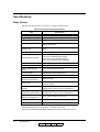
Specifications . . . . . . . . . . . . . . . . . . . . . . . . . . . . . . . . . . . . . . . . . . . . . . . . . . . . . . . . . . . . . .A-2
Base Printer. . . . . . . . . . . . . . . . . . . . . . . . . . . . . . . . . . . . . . . . . . . . . . . . . . . . . . . . . . . . .A-2
Consumables. . . . . . . . . . . . . . . . . . . . . . . . . . . . . . . . . . . . . . . . . . . . . . . . . . . . . . . . . . . .A-3
Appendix B. Paper Specifications
Media Guidelines . . . . . . . . . . . . . . . . . . . . . . . . . . . . . . . . . . . . . . . . . . . . . . . . . . . . . . . . . . . B-1
General Media Recommendations . . . . . . . . . . . . . . . . . . . . . . . . . . . . . . . . . . . . . . . . . . . B-1
Paper Specifications . . . . . . . . . . . . . . . . . . . . . . . . . . . . . . . . . . . . . . . . . . . . . . . . . . . . . B-2
Paper Weight . . . . . . . . . . . . . . . . . . . . . . . . . . . . . . . . . . . . . . . . . . . . . . . . . . . . . . . . . . . B-3
Paper Color . . . . . . . . . . . . . . . . . . . . . . . . . . . . . . . . . . . . . . . . . . . . . . . . . . . . . . . . . . . . B-3
Paper Composition . . . . . . . . . . . . . . . . . . . . . . . . . . . . . . . . . . . . . . . . . . . . . . . . . . . . . . B-4
Paper Cut . . . . . . . . . . . . . . . . . . . . . . . . . . . . . . . . . . . . . . . . . . . . . . . . . . . . . . . . . . . . . . B-4
Paper Smoothness . . . . . . . . . . . . . . . . . . . . . . . . . . . . . . . . . . . . . . . . . . . . . . . . . . . . . . . B-4
Paper Fusing . . . . . . . . . . . . . . . . . . . . . . . . . . . . . . . . . . . . . . . . . . . . . . . . . . . . . . . . . . . B-4
Moisture . . . . . . . . . . . . . . . . . . . . . . . . . . . . . . . . . . . . . . . . . . . . . . . . . . . . . . . . . . . . . . . B-5
Paper Curl . . . . . . . . . . . . . . . . . . . . . . . . . . . . . . . . . . . . . . . . . . . . . . . . . . . . . . . . . . . . . B-6
Recycled Paper . . . . . . . . . . . . . . . . . . . . . . . . . . . . . . . . . . . . . . . . . . . . . . . . . . . . . . . . . B-7
Grain Direction . . . . . . . . . . . . . . . . . . . . . . . . . . . . . . . . . . . . . . . . . . . . . . . . . . . . . . . . . B-7
Paper Smoothness . . . . . . . . . . . . . . . . . . . . . . . . . . . . . . . . . . . . . . . . . . . . . . . . . . . . . . . B-7
Special Media . . . . . . . . . . . . . . . . . . . . . . . . . . . . . . . . . . . . . . . . . . . . . . . . . . . . . . . . . . . . . . B-8
Preprinted Paper . . . . . . . . . . . . . . . . . . . . . . . . . . . . . . . . . . . . . . . . . . . . . . . . . . . . . . . . B-8
Prepunched Paper . . . . . . . . . . . . . . . . . . . . . . . . . . . . . . . . . . . . . . . . . . . . . . . . . . . . . . B-10
Adhesive Labels . . . . . . . . . . . . . . . . . . . . . . . . . . . . . . . . . . . . . . . . . . . . . . . . . . . . . . . B-12
Perforated Paper . . . . . . . . . . . . . . . . . . . . . . . . . . . . . . . . . . . . . . . . . . . . . . . . . . . . . . . B-15
Printing Guidelines . . . . . . . . . . . . . . . . . . . . . . . . . . . . . . . . . . . . . . . . . . . . . . . . . . . . . . . . . B-17
Printable Area . . . . . . . . . . . . . . . . . . . . . . . . . . . . . . . . . . . . . . . . . . . . . . . . . . . . . . . . . B-17
Preprinted Lines . . . . . . . . . . . . . . . . . . . . . . . . . . . . . . . . . . . . . . . . . . . . . . . . . . . . . . . . B-18
Preprint Inhibited Area . . . . . . . . . . . . . . . . . . . . . . . . . . . . . . . . . . . . . . . . . . . . . . . . . . . B-18
Glossary
TOC-4
Table of Contents
OG
L
04
SAFETY SUMMARY
General Safety Guidelines
Before operating the machine, read the following instructions carefully:
■
Allow all the operating procedures provided in this manual.
■
Pay special attention to and follow all the hazard warning on the machine and in
the manual. Failure to do so can cause injury to yourself or damage to the
machine.
■
The hazard warnings which appear on the warning labels on the machine or in the
manual have one of the following alert headings consisting of an alert symbol and
a signal ward, DANGER, WARNING, or CAUTION.
DANGER! : indicates an imminently hazardous situation which, if not avoided,
will result in death or serious injury.
WARNING!: indicates a potentially hazardous situation which, if not avoided,
can result in death or serious injury.
CAUTION!: indicates a hazardous situation which, if not avoided, will or can
result in minor or moderate injury, or serious damage of product.
The alert symbol shown left precedes every signal word for hazard
warnings, and appears in safety related descriptions in the manual.
The signal word ’NOTE’ is used to present warnings which are not directly related to
personal injury hazards.
■
Do not perform any operation or action in any way other than as provided in this
manual. When in doubt, call the designated field engineer.
■
Keep in mind that the hazard warnings in this manual or on the machine cannot
cover every possible case, as it is impossible to predict and evaluate all
circumstances beforehand. Be alert and use your common sense.
Safety Summary -1
OG
L
00
SAFETY SUMMARY
Hazard Warning Statements
WARNING Statement
■
“Use of controls, adjustments or performance of procedures other than those
specified in this manual may result in hazardous laser radiation exposure.” on
page Safety Summary-5
■
“Connect the power plug only to a properly rated power outlet. Otherwise, a fire
or shock hazard may result.” on page Safety Summary-8
■
“Never use multi-plug adaptors to plug multiple power plugs into the same power
source. Be sure to operate the printer on a sole-use receptacle. Multiple
connectors can cause overheating and a fire could result.” on page Safety
Summary-8
■
“The printer must be connected to the grounding power outlet for safe and proper
operation.” on page Safety Summary-8
■
“Apparatet må kun tilkoples jordet stikkontakt.” on page Safety Summary-8
■
“Apparaten skall ansulatas till jordat uttag när den ansluts till ett nätverk.” on
page Safety Summary-8
■
“Für einen sicheren und ordnungsgemäßen Betrieb muß der Drucker an eine
geerdete Steckdose angeschlossen werden.” on page Safety Summary-8
■
“Do not throw the toner bottle into a fire because it may suddenly burn, causing a
risk of fire or personal injury.” on page 4-6
■
“Dispose the toner bottle as incombustible waste.” on page 4-6
■
“Waste materials should be disposed of or incinerated under conditions which
meet all federal, state and local environmental regulations. Since regulations may
vary from one region to another, check with the agency that governs waste
disposal in your area for proper procedures.” on page 4-8
■
“Do not throw the developer bottle into a fire because it may suddenly burn,
causing a risk of fire or personal injury.” on page 4-16
■
“The Fuser Unit is very hot. Do not touch any parts of the Fuser Unit except those
parts which are used to replace the Fuser Cleaning Web.” on page 4-17
■
“The Fuser Unit is very hot. Do not touch any parts of the Fuser Unit except those
parts which are used to remove the paper. It is better to use the Bamboo Tweezers
to remove the paper. (The Bamboo Tweezers is an attached accessory.)” on page
4-35
CAUTION Statement
■
“Never unplug or replug the printer while it is on.” on page Safety Summary-9
■
“Do not place the printer near heaters or volatile, flammable, or combustible
materials.” on page Safety Summary-10
Safety Summary -2
OG
L
01
SAFETY SUMMARY
■
“Once the printer is powered off, wait at least 5 seconds to next power on.” on
page 1-6
■
“If the message “Open the Fuser cover, and check that there is no paper” is
displayed on the OCP, open the Fuser cover and check the Fuser unit refer to
Chapter 4.” on page 1-9
■
“If the printer does not power on, power off the printer, wait at least 30 seconds,
then power on the printer again.” on page 1-6
■
“You must set the correct paper weight value. The incorrect paper weight value
may cause paper jam.” on page 3-20
■
“Depending on amount of paper, the Basket is very heavy. Take care not to hurt
your back when lifting a heavy Basket.” on page 3-30
■
“Toner is not harmful to the human body, but if some toner has come in contact
with your skin or clothes, you should wash it immediately with cold water.” on
page 4-3
■
“The toner is not harmful to the human body. However, take care not to inhale or
swallow it because you may feel sick.” on page 4-6
■
“If the toner goes into your eyes, immediately rinse with running water. If
affected eyes are not rinsed, it may become injured. If the skin or clothing is
contacted, wash with soap and water” on page 4-6
■
“Hold the developer bottle when you turn the cap so that the bottle is not turned
together with the cap.” on page 4-10
■
“Hold the developer bottle when you turn the cap so that the bottle is not turned
together with the cap.” on page 4-13
■
“Incorrect setting of the Developer Bottle cause damage to the Developer Unit.
Make sure the setting of the Developer Bottle before go to next step.” on page 413
■
“If the developer is spilled out on the floor, the floor becomes very slippy. This
may result in a fall and/or injury. Clean up the spilled developer with a toner-safe
vacuum cleaner.” on page 4-15
■
“If the developer goes into your eyes, immediately rinse with running water. If
affected eyes are not rinsed, it may become injured. If the skin or clothing is
contacted, wash with soap and water” on page 4-15
■
“Surface of the Photoconductor Drum (OPC Sheet) is very sensitive. Carefully
remove a paper to avoid scratch the surface of the Photoconductor Drum.” on
page 4-32
■
“The paper in the Fuser Unit must be removed by step 8 to step 14 when the Fuser
Jam is happened. If the paper remains in the Fuser Unit, paper is scorched, or it
causes another paper jam, or it causes some mechanical damage.” on page 4-33
■
“Incompletion of closing the Fuser Unit Cover and the Paper Guide cause damage
to the Fuser Unit. Make sure the Fuser Unit Cover and the Paper Guide are
completely closed.” on page 4-36
■
“Power off the printer prior to cleaning.” on page 4-51
Safety Summary -3
OG
L
02
SAFETY SUMMARY
■
“Do not use solvent on the printer. Using solvent may dissolve the plastic and
paint of the printer.” on page 4-51
■
“Do not use cleaning solutions to clean inside and around the printer. Use only a
water-moistened cloth.” on page 4-51
■
“For cleaning up toner or developer spillage, use a specially-designed toner-safe
vacuum cleaner. If you use a regular vacuum cleaner, the drawn toner/developer
powder may scatter in the air. If you inhale or your eyes come into contact with
such powder, you may feel sick or injure your eyes. Further, the drawn toner/
developer powder may render the vacuum cleaner defective when it enters the
vacuum cleaner’s motor section.” on page 4-51
■
“The Paper Height Sensor in the Tray is sensitive. Carefully cleaning a Tray to
avoid a damage to the Paper Height Sensor.” on page 4-52
■
“If the message “Open the Fuser cover, and check that there is no paper” is
displayed with E31x Call for Service error, open the Fuser cover and check the
Fuser unit refer to Chapter 4.” on page 5-24
■
“Do not use paper that contains CaCO3 as it can drastically reduce fuser life.” on
page B-4
■
“Adhesive that comes in contact with the printer may contaminate the
photoconductor and the internal printer mechanism. To test label stock for
adhesive exposure, press a sheet of plain paper against a sheet of label stock. The
plain paper should not adhere to the label stock at all.” on page B-12
Safety Summary -4
OG
L
02
SAFETY SUMMARY
Laser Safety
This printer is certified as a Class 1 laser product under the U.S. Department of Health
and Human Services (DHHS) Radiation Performance Standard according to the
Radiation Control for Health and Safety Act of 1968. This means that the printer does
not emit hazardous laser radiation.
Since radiation emitted inside the printer is completely confined within the protective
housings and external covers, the laser beam cannot escape from the machine during
any phase of user operation.
The Center for Devices and Radiological Health (CDRH) of the U.S. Food and Drug
Administration implemented regulations for laser products on August 1976. These
regulations apply to laser products marketed in the United States. The label on the
printer indicates compliance with the CDRH regulations and must be attached to laser
products marketed in the United States.
This printer is classified as a Class 1 laser product both under EN60825 and the Code
of Federal Regulations, 1040.10 of Title 21.
LOUKAN 1 LASERLAITE
CLASS 1 LASER APPARAT
Internal Laser Radiation
Maximum Radiation Power:
Wave Length:
10mW x 4 diodes
780nm
WARNING!
Use of controls, adjustments or performance of procedures other than
those specified in this manual may result in hazardous laser radiation
exposure.
Safety Summary -5
OG
L
00
SAFETY SUMMARY
Certifications
FCC Notice
This equipment has been tested and found to comply with the limits for a Class A
digital device pursuant to Part 15 of FCC Rules. These limits are designed to provide
reasonable protection against harmful interference when the equipment is operated in
a commercial environment. This equipment generates, uses, and can radiate radio
frequency energy and, if not installed and used in accordance with this user’s guide,
may cause harmful interference to radio communications. Operation of this equipment
in a residential area is likely to cause harmful interference. If this occurs, users are
required to correct the interference at their own expense.
Use of shielded cables is required to comply with Class A limits in Subpart B of
Part 15 of FCC Rules.
Do not make any changes or modifications to the equipment other than those specified
in this user’s guide.
You may find the following booklet prepared by the Federal Communications
Commission helpful: How to Identify and Resolve Radio - TV Interference Problems.
This booklet is available from the U.S. Government Printing Office, Washington, D.C.
20402, Stock No. 004-000-00345-4.
Canadian Certification
This Class A digital apparatus complies with Canadian ICES-003.
Cet appareil numérique de la classe A est conforme à la norme NMB-003 du Canada.
VCCI Notice (Japan)
This is a class 1 product based on the standard of the Voluntary Control Council for
Interference by Information Technology Equipment (VCCI). If this equipment is used
in a domestic environment, radio disturbance may arise. When such trouble occurs, you
may be required to take corrective actions.
Safety Summary -6
OG
L
00
SAFETY SUMMARY
Declaration of Conformity for Safety/EMI
The Printer, High Capacity Feeder and Container Stacker conform to the directives and
standards shown below. For further information or to request a copy of the Declaration
of Conformity, contact your Distributor.
1. EMC directive 89/336/EEC, 92/31/EEC
Emission:EN 55022 (Class A) / 1998 / A1: 2000 / A2: 2003
EN61000-3-2: 2001
EN61000-3-3 / 1995 / A1: 2001
Immunity:EN55024 / 1998 / A1: 2001 / A2: 2003
IEC61000-4-2 / 1995/A1:1998 / A2: 2001
IEC61000-4-3 / 2002
IEC61000-4-4 / 1995 / A1:2000 / A2: 2001
IEC61000-4-5 / 1995 / A1: 2001
IEC61000-4-6 / 1996/ A1: 2001
IEC61000-4-8 / 1993 / A1: 2000
2. Low Voltage Directive 73/23/EEC incl. Amendments:
EN60950:1: 2001
EN60825-1:1993 / A1: 1997 / A2: 2001
3. CE Marking Directive 93/68/EEC
This equipment has been tested and found to comply with the limits for a class A
Information Technology Equipment in accordance with the European Standard
EN55022.
These limits are designed to provide reasonable protection against unacceptable
interference in either commercial or industrial environments. This equipment
generates, uses, and can radiate radio signals and if it is not installed and used in
accordance with the instructions detailed in this user’s guide, it may cause unacceptable
interference to radio communication installations and equipment. The operation of this
equipment in a residential area is likely to cause unacceptable interference in which
case you may be required to correct the source of the interference at your own expense.
In order to maintain compliance to the class A regulations, shielded cables must be used
with this equipment. Operation of this equipment without shielded cables is likely to
cause interference to radio and television receivers thereby degrading their reception.
Please be aware that changes and modifications made to the equipment without prior
approval of the manufacturer could negate your permission to operate the equipment.
Declaration of Conformity for RoHS
The Printer, High Capacity Feeder, and Container Stacker conform to the directives and
standards shown below. For further information or to request a copy of the Declaration
of Conformity, contact your Distributor.
1. Restriction of Hazardous Substances (RoHS) Directive2002/95/EC
Safety Summary -7
OG
L
01
SAFETY SUMMARY
When Installing and Relocating the Printer
Power Specifications
Rated Voltage
Rated
Frequency
Rated Current
200/208/220/230/240V
50/60Hz
21A
380/400/415V
50/60Hz
21A
Power Cords
WARNING!
Connect the power plug only to a properly rated power outlet. Otherwise,
a fire or shock hazard may result.
Never use multi-plug adaptors to plug multiple power plugs into the same
power source. Be sure to operate the printer on a sole-use receptacle.
Multiple connectors can cause overheating and a fire could result.
Ensure that the plug connection is free of dust. In a damp environment, a contaminated
connector can draw a non-negligible amount of current that can generate heat and
eventually cause a fire over an extended period of time.
To prevent the risk of electric shocks and personal injury, fire, and printer damage:
■
Always use the power cord provided with your printer. When an extension power
cord is required, always use a properly rated cord.
If the power cord is not provided, use the following types of power cords:
❒
For North America:
4 wires, Type SJT 4x12 AWG (4x4.0 mm2) or thicker
Rated min. 300V/25A (with grounding plug).
❒
For Europe
5 wires, min. 5x4.0 mm2
Harmonized (<HAR>), Rated min. 300V/25A (with grounding plug).
WARNING!
The printer must be connected to the grounding power outlet for safe and
proper operation.
Apparatet må kun tilkoples jordet stikkontakt.
Apparaten skall ansulatas till jordat uttag när den ansluts till ett nätverk.
Für einen sicheren und ordnungsgemäßen Betrieb muß der Drucker an
eine geerdete Steckdose angeschlossen werden.
Safety Summary -8
OG
L
01
SAFETY SUMMARY
■
Do not attempt to rework, pull, bend, chafe, or otherwise damage the power cord.
Do not place a heavy object on the cord.
■
Never touch a power cord with wet hands.
■
If your printer produces smoke, excessive heat, unusual noises or odors, or if any
liquid is spilled into the printer, immediately switch off and unplug the printer.
■
If the power cord is broken or insulated wires are exposed, be sure to get them
replaced. (Do not use the damaged cord.)
CAUTION!
Never unplug or replug the printer while it is on.
■
When unplugging the printer, grasp the plug instead of the cord.
■
Be sure to switch off and unplug the printer before accessing its interior for
cleaning or maintenance.
■
When the printer is not used over an extended period of time, switch it off and
unplug it.
■
Once a month, unplug the printer and check that:
❒
the power cord is plugged firmly into a receptacle.
❒
the power cord is not cracked or frayed.
❒
the plug is not excessively heated, rusted, or bent.
❒
the plug and receptacle are free of dust.
NOTE:
If you notice any unusual conditions, contact your service representative.
Safety Summary -9
OG
L
01
SAFETY SUMMARY
Positioning the Printer Safely
To prevent the risk of electric shocks and personal injury, fire, and printer damage:
■
Switch off the printer before connecting the interface cable or optional accessory.
CAUTION!
Do not place the printer near heaters or volatile, flammable, or
combustible materials.
■
Place the printer on a level and sturdy surface that can withstand the printer’s
weight. If tilted, the printer may fall over and cause injuries.
■
Do not place the printer in a hot, humid, dusty, or poorly ventilated environment.
■
When moving the printer, be sure to unplug the power cord from the outlet. If the
printer is moved with the power cord connected, it can cause damage to the cord.
■
When moving the printer, do not tilt it more than 10 degrees. If tilted excessively,
the printer may fall over and cause injuries.
■
If you need to move the printer over a long distance, consult your Technical
Representative.
Environmental Limit
■
The printer is capable of operating normally within the following recommended
environmental limits:
❒
Temperature range: 60°-89°F (16°-32°C).
❒
Humidity range: 20-80% RH (no condensation).
NOTE:
Sudden temperature fluctuations can affect print quality. Rapid heating of
a cold room can cause condensation inside the printer, directly interfering
with image transfer.
■
Do not expose the printer to direct sunlight, or the printer's performance may
decline.
Safety Summary -10
OG
L
01
SAFETY SUMMARY
Operating Precautions
■
Take care not to allow ties, sleeves, shirts, or long hair to be caught in the printer
while operating.
■
Be careful not to touch the hazardous parts near the caution labels.
■
Be sure to avoid accidentally powering on the printer or pressing switches on the
operator’s panel while operating the printer.
■
Never touch the high voltage portions of the printer, where caution labels are
attached, when the printer is on. It may cause personal injuries if accidentally
touched.
■
Make sure that the printer paper complies with the supplies specifications.
Printing on paper which does not comply with the specifications may result in
paper jams and print quality degradation.
■
Properly load the paper into the hopper to prevent paper skew and paper jams.
■
It is absolutely necessary to follow the procedures and instructions described in
this manual in order to optimize the printer’s performance and to assure its safe
operation.
Safety Summary -11
OG
L
01
SAFETY SUMMARY
SAFETY PRECAUTIONS
■
Always keep the area around the printer tidy. Use the printer under the proper
lighting (500-1,000 lux.). Keep sufficient space around the printer so the hoppers
can be pulled forward. Space required in the vicinity of the printer is as follows:
Front side: 1 meters
Left, right and rear side: 1 meter
■
Do not place anything on the printer.
■
Do not open any covers during printing operation. It may cause personal injuries
if moving elements or electrical parts are accidentally touched.
■
Be particularly careful when working in the fuser unit area. Do not touch the
inside of the fuser unit. The fuser unit becomes very hot (approx. 374°F [190°C])
and it may cause personal injuries if accidentally touched.
■
Toner and developer are comprised of powdery particles. Avoid inhaling toner or
developer when it accidentally spills and circulates. If it spills on the floor,
immediately clean it with water-damped cloth. Do not leave it on the floor. It may
cause accidents if stepped on as they are slippery beads of metal.
■
Limit your operations to those described in this manual. Contact the field engineer
or service technician for further operations which are not explained in this
manual.
■
This equipment generates ozone. Long-term exposure should be limited to 0.1
ppm calculated as an 8 hr. time weighted average concentration. Provide proper
ventilation. Avoid installing the unit in a small room (smaller than 27cubic
meter). If installing in a space smaller than 27cubic meter, frequent ventilation is
necessary
Safety Summary -12
OG
L
02
SAFETY SUMMARY
Care of Printer Supplies
■
Store the paper, toner, and other supplies in a place free from direct sunlight and
away from any heating apparatus. Keep them in a dry, cool, clean environment.
■
Store paper that has been removed from its wrapper, but not loaded into the
drawer, in a sealed, plastic bag in a cool, dark place.
■
If your hands become soiled with toner, wash them with soap and water
immediately.
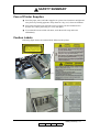
Caution Labels
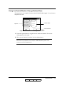
Following figure shows the caution labels affixed on the printer.
Safety Summary -13
OG
L
01
SAFETY SUMMARY
Blank
Safety Summary -14
OG
L
01
Introduction
About This Manual
This manual provides easy access to the information you need to operate the 156PPM
(Pages Per Minute) laser printer.
NOTE:
This User’s Guide is intended to be viewed online. When viewing it online,
use the bookmarks and page reference links for easy navigation
throughout the document.
To find out about a specific topic, refer to:
■
SAFETY SUMMARY – For safety information and printer characteristics,
including environmental and electrical requirements.
■
Chapter 1: Printer Overview – For printer components and features.
■
Chapter 2: Operator Control Panel – To access and use the liquid crystal display
(LCD) window and the menus screens.
■
Chapter 3: Paper Handling – For media recommendations and paper handling
procedures.
■
Chapter 4: Care and Maintenance – For detailed instructions on replacing
consumables, clearing paper jams, and cleaning and maintaining the printer.
■
Chapter 5: Troubleshooting – For information on printing problems and printer
error and warning messages.
■
Chapter 6: Web Utilities – For information on accessing the printer via the
Internet or your company’s Intranet.
■
Appendix A: Specifications – For printer specifications.
■
Appendix B: Paper Specifications – For media specifications and printing
guidelines.
■
Glossary – For definitions of terms and acronyms.
Audience
This manual is written for those persons responsible for operating the printer. A basic
understanding of computer equipment and its operations is required.
Introduction
OG
L
00
0-1
Manual Conventions
The following conventions are used in this manual:
■
Bold and Italics are used sparingly for emphasis.
■
Information you enter: Looks Like This.
■
Key Names (or Labels): Look Like This.
■
System messages: Look Like This.
■
Variable user information: Looks Like This.
Pay particular attention to Notes, Cautions, and Warnings. These alert you to critical
information, as follows:
NOTE:
Provides important additional information.
CAUTION!
Alerts you to an operating procedure, practice, or condition that, if not
strictly observed, might result in damage to the equipment.
WARNING!
Alerts you to an operating procedure, practice, or condition that, if not
strictly observed, can result in safety hazards to personnel, severe injury,
or loss of life.
For More Information
Refer to the following related documents for more details about your printer.
0-2
■
Installation Guide
■
Engine Maintenance Manual
■
Controller Maintenance Manual
■
Parts Catalog
Introduction
OG
L
00
Chapter 1
Printer Overview
What This Chapter Provides
This chapter describes the parts and functions of the printer.
■
Printer Features
■
External View of the Printer
■
Internal View of the Printer
■
Powering On the Printer
■
Powering Off the Printer
■
Space Required for Installation
Printer Overview
OG
L
00
1-1
Printer Features
The printer is a high-speed, heavy duty laser printer for a 1.5M page/month printing
environment. It incorporates a wide variety of features:
■
■
High-Speed and High-Quality Printing.
❒
Print speed is up to 156 pages per minute (ppm), A4/Letter/Legal (Simplex).
❒
The printing output is at a resolution of 600 dots per inch (dpi), assuring
razor-sharp graphic and text output, even at very small point sizes.
Flexible Paper Source and Delivery.
Paper Source:
❒
Standard – One 2,500-sheet and one 1,000-sheet universal paper trays.
❒
Option – High Capacity Feeder with 3,000 to 12,000-sheet capacity.
Paper Delivery:
❒
Standard – Container Stacker with 2,000 to 4,000-sheet capacity and stacking
capability.
❒
Option – Additional Container Stacker with 2,000 to 4,000-sheet capacity and
stacking capability.
■
Multiple Original Printing (MOP) – for printing of multiple collated document
sets without multiple file transfers. Processes PCL and PostScript jobs once,
stores the images on disk, and prints each set from disk (after the first set).
■
Virtual Printer Technology (VPT) – allows a single printer to offer print services,
or virtual printers, each of which is configured by the Network Administrator.
■
Web Utilities – for remote access to the printer through the Internet or your
company’s Intranet.
■
Ergonomic operation.
❒
1-2
The easy-to-read display clearly shows the operational status of the printer.
Printer Overview
OG
L
00
■
High-volume printing.
❒
Two standard paper trays with approximately 3,500-sheet capacity total.
❒
Optional High Capacity Feeder (HCF) adds up to 12,000 additional sheets.
❒
Together they allow continuous printing of up to 15,500 sheets.
■
Supports a wide-range of media types (plain, bond, letterhead, special application,
recycled, labels) and sizes. See “Paper” on page 3-2 for more information.
■
Printer Language Support.
❒
PCL5e and PCL XL printer language.
❒
PostScript Level III (Adobe) printer language.
❒
PDF and TIFF files printing.
NOTE:
PDF Files printing is only supported for PDF Version 1.3.
■
■
■
Network.
❒
Ethernet 10/100/1000 Base-T with onboard network
❒
Additional Ethernet 10/100 Base-T with Multi-protocol NIC option.
Network Protocol.
❒
TCP/IP, LPR/LPD and IPP with onboard network.
❒
TCP/IP, LPR/LPD, NetWare IPX/SPX, Ethertalk with Multi-protocol NIC
option.
Easy installation of additional fonts and macros using the PCL Startup File.
I/O Configurations
■
Ethernet 10/100/1000 Base-T with onboard network.
■
Additional Ethernet 10/100Base-T with Multi-protocol NIC option.
Operator Control Panel
The Operator Control Panel (OCP) is your physical interface to the printer's features
and functions. From the control panel, you can monitor the printer's operating status
and configure the specific printer functions.
See Chapter 2 for detailed information about the OCP.
Printer Overview
OG
L
00
1-3
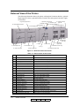
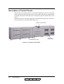
External View of the Printer
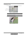
The following illustration shows the printer with optional Container Stacker, optional
High Capacity Feeders, optional Finisher Transfer Unit and optional Attention Light
are installed.
21. Transit Pass Unit
4. Operator Control Panel
Type 156
20. Attention Light
13. Sample Tray
14. Container Stacker 1
1. Power Switch
17. Container Stacker 2
3. Toner Supply Cover
7. High Capacity Feeder 1
10. High Capacity Feeder 2
18. Container 2
Lower Tray
6. Tray 2
12. HCF2 Upper Tray
9. HCF1 Upper Tray
11. HCF2 Lower Tray
19. Container 2
Upper Tray
2. Front Cover
15. Container1 Lower Tray
5. Tray 1
16. Container1 Upper Tray
8. HCF1 Lower Tray
Figure 1-1. External View of the Printer
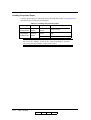
Table 1-1. External View of the Printer
Key
1-4
Component
Description
1
Power Switch
Press to turn the printer on and off.
2
Front Cover
Open to replace units, clear paper jams, or clean the printer.
3
Toner Supply Cover
Open to replenish the toner supply.
4
Operator Control Panel (OCP)
Displays printer status and menu information.
5
Tray 1
Holds up to 2,500 sheets of paper.
6
Tray 2
Holds up to 1,000 sheets of paper.
7
High Capacity Feeder 1
Two 3,000-sheet input trays.
8
HCF1 Lower Tray
Holds up to 3,000 sheets of paper.
9
HCF1 Upper Tray
Holds up to 3,000 sheets of paper.
10
High Capacity Feeder 2
Two 3,000-sheet input trays.
11
HCF2 Lower Tray
Holds up to 3,000 sheets of paper.
12
HCF2 Upper Tray
Holds up to 3,000 sheets of paper.
13
Sample Tray
100-sheet output tray
14
Container Stacker 1
Two 2,000-sheet output trays
15
Container1 Lower Tray
Stacks up to 2,000 sheets of paper.
16
Container1 Upper Tray
Stacks up to 2,000 sheets of paper.
17
Container Stacker 2
Two 2,000-sheet output trays
18
Container2 Lower Tray
Stacks up to 2,000 sheets of paper.
19
Container2 Upper Tray
Stacks up to 2,000 sheets of paper.
20
Attention Light
Indicates error, warning and printer ready status.
21
Transit Pass Unit Type 156
Paper transport unit for Post Device.
Printer Overview
OG
L
01
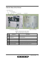
Internal View of the Printer
1. Toner Supply Cover
2. Developer Duct
3. Drum Unit
6. SF Cover
4. Fuser Unit
5. Toner Bottle / Toner Bag
7. Main AC Power Switch
Figure 1-2. Internal View of the Printer
Table 1-2. Internal View of the Printer
Key
Component
Description
1
Toner Supply Cover
Open this cover when supplying the new toner.
2
Developer Duct
Mount the developer bottle onto the developer duct to replace
consumed developer
3
Drum Unit
OPC drum.
4
Fuser Unit
Fuses the toner on the paper.
5
Toner Bottle/Toner Bag
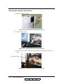
Collect the waste toner.
6
SF Cover
Open this cover when replacing the Fine Filter.
7
Main AC Power Switch
Turn the printer main AC power on and off
Printer Overview
OG
L
01
1-5
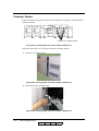
Powering On the Printer
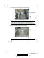
The printer has two power switches, the Main AC Power Switch and the Power
Switch. The location of switches are shown below. Both switches are marked “I” for
power on.
Power Switch
Main AC Power Switch
Figure 1-3. Powering On the Printer
When the printer is powered on, the printer go through a power-up sequence that takes
approximately 5 minutes. During the power-up sequence, the printer runs a series of
internal tests.
CAUTION!
Once the printer is powered off, wait at least 5 seconds to next power on.
If the printer does not power on, power off the printer, wait at least 30
seconds, then power on the printer again.
1-6
Printer Overview
OG
L
00
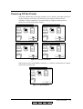
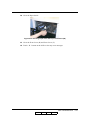
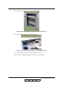
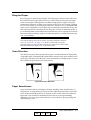
Powering Off the Printer
The printer should only be powered off when it is in a “Ready” state; that is, there are
no jobs printing or processing. The following OCP displays indicate normal
conditions. In these conditions, wait until printing is complete and the printer is
Ready, then switch off the Power Switch.
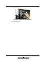
Figure 1-4. Normal Conditions
If the printer status is Pause/Offline, touch the “” button to return printer to a Ready
status before powering off.
Figure 1-5. Pause/Offline
Printer Overview
OG
L
00
1-7
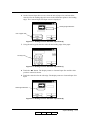
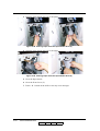
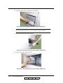
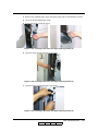
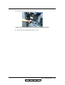
Clearing Error Conditions
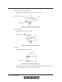
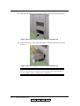
OCP Alternates between Ready and Processing
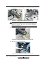
1. Cancel the print job(s). For detail of canceling print job,
Figure 1-6. OCP Alternates between Ready and Processing
E0XX, E1XX Error
1. Correct the error and touch the “” button on the OCP display.
2. Wait until printing is complete and the printer returns to Ready, then switch off
the main power.
Figure 1-7. E0XX, E1XX Error
1-8
Printer Overview
OG
L
00
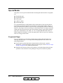
E2XX, EC#XX Call for Service Error
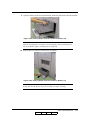
1. Touch the “” button on the OCP display.
2. Wait until printing is complete and the printer returns to Ready.
Figure 1-8. Call for Service Error
CAUTION!
If the message “Open the Fuser cover, and check that there is no paper” is
displayed on the OCP, open the Fuser cover and check the Fuser unit refer
to Chapter 4.
3. If the Call for Service error persists, cancel the print job(s), power off the printer,
and contact your authorized service technician.
Printer Overview
OG
L
01
1-9
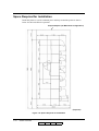
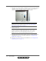
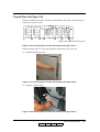
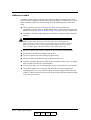
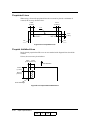
Space Required for Installation
Install the printer in a well-ventilated place and keep around the printer as shown
below for safe and effective operation.
Required Space (for Maximum Configuration)
(Top View)
Figure 1-9. Space Required for Installation
1-10
Printer Overview
OG
L
01
Chapter 2
Control Panels
What This Chapter Provides
This chapter contains information on the following topics.
■
Description of Control Panels
■
OCP Menu Icons and Buttons
■
Using the OCP Menus
■
OCP Menu Structure
■
Sub Panel
Control Panels
OG
L
00
2-1
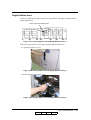
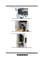
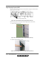
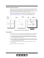
Description of Control Panels
The Operator Control Panel (OCP) is a touch panel display that you use to set up print
options and monitor job and printer status. It is also used by the Network Administrator
to configure the printer and by the Service Technician to perform maintenance on the
printer.
This printer also have sub panel equipped to each Input and Output Trays. Sub panel
has some functions to each Input and Output Trays.
Operator Control Panel
Sub Panel
(Output Tray)
Sub Panel (Input Tray)
Figure 2-1. Operator Control Panel
2-2
Control Panels
OG
L
00
OCP Menu Icons and Buttons
The menus are accessed via the touch panel. Each OCP menu consists of icons and
buttons that you use to make selections. The icons and buttons are defined below. See
“Main Menu” on page 2-8 for more icons.
Table 2-1. OCP Menu Icons and Buttons
Icon or
Button
Name
?
Help
i
Information
From the Main Menu, displays information about the printer and
consumables.
From relevant screens, displays an illustration of the paper trays
or finisher trays.
Pause/Offline
Touch to pause the printer.
Touch to display Help on the current screen.
Resume/Online When the printer is offline, touch to return to Ready status.
Return to Main
Menu
Function
Touch to cancel the current selection and return to the Main Menu.
Previous Menu Touch to cancel the current selection and return to the previous screen
or menu.
More Options
Touch to display additional options for the current selection.
Enter or Accept Confirm or Done. Touch to confirm your selection and return to the
previous screen or menu.
Sample
–
Touch to duplicate a current printing page and output to the sample tray.
Clear Button
Touch to erase entire entry.
Delete Button
Touch to erase last character entered.
Ten Key
Brightness
Contrast
Status Bar
Use to enter numeric values.
Use to adjust backlight value of the OCP display.
Use to adjust the contrast level of the OCP display.
Displays the current screen name and/or any system messages.
Control Panels
OG
L
00
2-3
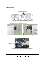
Using the OCP Menus
There are 4 types of OCP Menu displays.
■
Option Button
■
Ten Key Pad
■
Change Button (+ / -)
■
Change Button (Enable/Disable)
A brief description of each menu and how to use it follows.
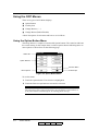
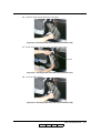
Using the Option Button Menu
The image below is a sample of a menu with Option buttons. The status bar indicates
the current setting. In this sample there is a More Options button indicating there are
more options to choose from on the following page.
Status Bar
Option Buttons
Previous Menu
More Options
Enter/Accept
Figure 2-2. Option Button Menu
To use this menu,
1. Touch the Option button. The selection is highlighted.
2. Touch the Enter/Accept button to activate the selection.
NOTE:
The selection will be ignored if the Enter/Accept button is not touched, or
if any other button is touched prior to touching Enter/Accept.
2-4
Control Panels
OG
L
00
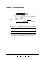
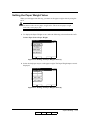
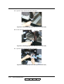
Using the Ten Key Pad Menu
The image below is a sample of a menu with a ten key pad. It is used to enter numeric
values.
Status Bar
Erase Entire Entry
Text Box
Erase Last Digit
Unit Value
Ten Key Pad
Previous Menu
Enter/Accept
Figure 2-3. Ten Key Pad Menu
To enter a value,
1. Touch the appropriate numbers on the pad. The value appears in the Text Box.
2. Touch the desired Unit Value button (if applicable).
3. Touch the Enter/Accept button to activate the entry.
NOTE:
The entry will be ignored if the Enter/Accept button is not touched, or if
the Previous Menu button is touched prior to touching Enter/Accept.
Control Panels
OG
L
00
2-5
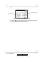
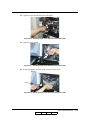
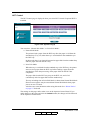
Using the + / - Change Button Menu
The image below is a sample of a menu with a + / - change button. It is used to increase
and decrease the OCP brightness and contrast. The current value is displayed to the
right of the icon.
Decrease -
10
10
Current Value
3
Increase +
Previous Menu
Enter/Accept
Figure 2-4. + / - Change Button Menu
To increase or decrease the value,
1. Touch the + or - to adjust brightness or contrast. The numeric value and the
display will change immediately.
NOTE:
Brightness control is not displayed in the production model after April ‘06.
Touch the Enter/Accept button to activate setting.
NOTE:
The setting will be ignored if the Enter/Accept button is not touched, or if
the Previous Menu button is touched prior to touching Enter/Accept.
2-6
Control Panels
OG
L
01
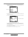
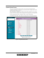
Using the Enable/Disable Change Button Menu
The image below is a sample of a menu with an Enable/Disable toggle. It is used to turn
an option on or off.
40 seconds
Disabled
Options
Disabled
Current Status
Middle
Previous Menu
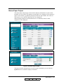
Figure 2-5. Enable/Disable Change Button Menu
1. Touch the Option Button to toggle between enable and disable. The current
setting appears to the right.
2. When you are finished, touch the Previous Menu button.
NOTE:
The Enter/Accept button is not used for Enable/Disable options. The
setting is activated immediately.
Control Panels
OG
L
02
2-7
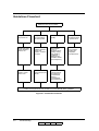
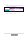
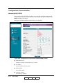
OCP Menu Structure
The OCP menu is structured as shown on the following pages. A top level menu screen
is shown followed by a description of the options on the screen. A table that outlines
the complete structure of the menu is also provided. Each box in the table represents an
OCP display menu. Use this information to assist you in setting printer options.
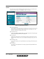
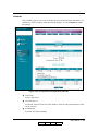
Main Menu
The Main Menu screen is shown below. A description of the icons that make up the
screen follows.
Status Bar
Help
Current Screen
Information
Printer Menu
Reports Menu
Setup Menu
Sample
Jobs Menu
Pause/Offline
Figure 2-6. Main Menu
Printer Menu
Touch to display the Printer Menu.
Setup Menu
Touch to display the Setup Menu.
Reports Menu
Touch to display the Reports Menu.
Jobs Menu
Touch to display the Cancel Printing screen and view a list of all jobs.
For other buttons or icons, see “Using the Option Button Menu” on page 2-4.
2-8
Control Panels
OG
L
00
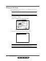
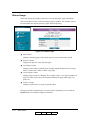
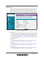
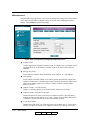
Information Menu
When you touch the information icon on the Main Menu this screen is displayed. You
can use it to determine the current settings and status of the options described below.
See Table 2-2 on page 2-10 for the complete Information Menu structure.
Figure 2-7. Information Menu
Printer
Touch to display information about the engine and controller software revision, error
counts, and the current paper type and source settings.
Consumables
Displays the status of the consumables: Toner, Developer Mix., OPC Sheet, and OPC
Sheet Counter.
Usage
Displays current information regarding print density, preventative maintenance, and
page counts.
Paper Output
Displays current information regarding the Output Tray of the printer.
Network
Displays information such as MAC and IP Address, Gateway Address, Subnet Mask
and HTTP Port.
Control Panels
OG
L
00
2-9
Table 2-2. Information Menu Structure
Level 1
Information
Level2
Printer
Consumable
Usage
Paper Output
Network
Level 3
1
2
HCF1 Lower (Note1)
HCF1 Upper (Note1)
HCF2 Lower (Note1)
HCF2 Upper (Note1)
Printer Graphic
Default Paper Source
Error Count of This Period
Controller Revision
Toner
Developer Mix
OPC Sheet
OPC Sheet Counter
Toner Coverage
PM Due In
Total Page Counter
Process Counter
Click Charge Counter
1L
1U
2L (Note2)
2U (Note2)
Printer Graphic
Network (AUX)
Network (NIC)
Level 4
Size, Status, Type, Weight
Size, Status, Type, Weight
Size, Status, Type, Weight
Size, Status, Type, Weight
Size, Status, Type, Weight
Size, Status, Type, Weight
Normal/Low
(current/limit k)
(current/limit k)
(current/limit k)
(current %)
(current k)
(current k)
(current k)
(current)
Paper Size, Basket Information, Basket Size
Paper Size, Basket Information, Basket Size
Paper Size, Basket Information, Basket Size
Paper Size, Basket Information, Basket Size
MAC Address
IP Address
Subnet Mask
Gateway Address
HTTP Port
MAC Address
IP Address
Subnet Mask
Gateway Address
HTTP Port
Note 1: This display is only available when the HCF is installed.
Note 2: This display is only available when the additional stacker is installed.
2-10
Control Panels
OG
L
02
Printer Menu
When you select Printer icon from the Main Menu, this screen is displayed. You use
the Printer Menu to gain access to the printing options described below. See Table 2-3
beginning on page 2-16 for the complete Printer Menu structure.
Figure 2-8. Printer Menu
Paper Source
■
Default
Defines the default paper tray. Use this when the paper source is not designated by
a host command. If a command from the host defines the paper source, the OCP
setting is ignored. Also if the paper source is specified in the Virtual Printer of the
Web, the OCP setting is ignored.
■
Paper Size
When Paper Size is selected the paper size of the currently selected paper source
is displayed. When the “Custom Size Switch” in the tray is set to “Standard”,
paper size is automatically detected.
To use the OCP to set the paper size to something other than the standard sizes, set
the Custom Size Switch in the tray to “Custom”, then select Paper Size on the
OCP. See “Paper Sizes, Paper Weights, Paper Types and Paper Color” on page 33 for more information.
■
Paper Type
Defines the paper type to desired input tray. The paper type screen displays
currently selected paper type, and press the option buttons to change to desired
paper type. See “Paper Sizes, Paper Weights, Paper Types and Paper Color” on
page 3-3 for more information.
■
Paper Color
Defines the paper color to desired input tray. The paper color screen displays
currently selected paper color, and press the option buttons to change to desired
paper color. See “Paper Sizes, Paper Weights, Paper Types and Paper Color” on
page 3-3 for more information.
Control Panels 2-11
OG
L
02
■
Paper Weight
Defines the paper weight to desired input tray. The paper weight screen displays
currently defined paper weight, and redefine to desired paper weight by this
screen. See “Paper Sizes, Paper Weights, Paper Types and Paper Color” on
page 3-3 for more information.
■
HV Adjust
The print position can be adjusted vertically and horizontally using the HV Adjust
option. The white arrow on the HV Adjust screen indicates paper feed direction.
The adjustment can be set to millimeters or inches and the range is -6.3 to +6.3
millimeters (-0.25 to +0.25 inches) in increments of 0.1 millimeter (0.01 inch).
Difference positions can be set for front and back side in duplex printing mode.
See “Setting the HV Adjust Values” on page 3-22 for more information.
■
Table Adjust
Defines the table height setting of the each input tray. This option can be adjusted
to five settings: +2, +1, Normal, -1 or -2. See “Setting the Table Adjust” on
page 3-24 for more information.
■
Paper Moisture
Defines the Paper Moisture setting to each input tray. This option can be adjusted
to four settings: Highest, Higher, Normal and Lower. See “Setting the Paper
Moisture” on page 3-26 for more information.
■
HCF Tray Control
Defines the HCF tray control mode if the optional HCF is installed. This option
can be set to the “Normal Pick Mode” or the “Prior Pick Mode”.
❒
Normal Pick Mode
The printer feeds a paper from the HCF tray after last paper is fed from the
standard tray (Tray 1/2) when the tray is switched from the standard tray to
the HCF tray.
In this mode, there is an interval between last paper fed from the standard tray
and first paper fed from the HCF tray.
❒
Prior Pick Mode
When the tray is switched from the standard tray to the HCF tray, the printer
starts to feed a paper from the HCF tray before feeding a paper from the
standard tray if the data processing of the paper fed from the HCF has
completed.
The paper fed from the HCF tray stops at the HCF exit, and is fed
continuously after last paper fed from the standard tray.
The tray switching time at Prior Pick Mode is shorter than Normal Pick Mode.
However more papers may be wasted than Normal Pick Mode when paper
jam or an error occurred.
Also there are some limitations when using this mode. See “Printer Notice”
on page 5-7 for detail.
2-12
Control Panels
OG
L
02
Paper Output
■
Default Output
Use this when the output tray is not designated by a host command. If a command
from the host defines the output tray, the OCP setting is ignored.
■
Stacking Level
Defines the Upper limit of the stacking level of each output tray. This option can
be adjusted to three settings: 50%, 75% or 100%.
Control Panels 2-13
OG
L
01
Options
■
Wait Timeout
Defines the waiting period (in seconds) from reception of last data to the
reception of next data. If data is not received within the defined period, the job is
cancelled. A command from the host will override the OCP setting.
■
LPD Queuing
Can be set to enable or disable. When set to disable, printer does not accept next
job via LPR/LPD protocol until current job process is completed.
■
Duplex Always
Can be set to enable or disable. When set to enable, the printer will always prints
the job by duplex mode.
■
Print Density
Print Density can be adjusted to five settings: Light, Semi-Light, Middle, SemiDark or Dark.
■
Auto Proof Sample
This function provides the automatic proof sample printing instead of manually
pressing the “Sample” button on the OCP. Print interval of the sample page can be
set from 0 to 5,000 every 500 sheet (0, 500, 1,000, 1,500, ... 5,000). For example,
If interval is set to “500”, then printer automatically duplicates the proof sample
to the Sample Tray every 500 sheet during printing. If the interval is set to “0”,
this function is disabled.
■
Cover Insert Mode
Defines the mode of the Cover Inserter when it is installed. Set to “Cover Insert”
when Cover Inserter is used. Set to “Bypass” when Cover Inserter is not used.
PostScript
■
Print Errors
Can be set to enable or disable. When set to enable, the printer will prints error
page when PostScript error is occurred.
■
Best Fit
Can be set to enable or disable. When set to enable, the printer will prints the page
image to fit the paper size.
■
Job Timeout
Defines the time limit (in seconds) for processing of the PostScript job.
■
Halftone Density
Halftone Density can be adjusted to three settings: Light, Medium or Dark..
NOTE:
The Halftone Density menu is only displayed when the Halftone Selection
in the Service menu is enabled.
2-14
Control Panels
OG
L
04
Test Print
Use this button to prints the test pattern for checking the print quality or the print
position. Following test patterns are available in this menu.
■
Cross Pattern
This option prints the combination of Horizontal/Vertical/Diagonal lines for
checking the print position. This pattern is printed by duplex.
■
Raster Pattern
This option prints the 8 page of the raster pattern and 8 page of the blank pages
(total 16 pages) for checking the print quality. This pattern is printed by simplex.
PCL
■
Wide A4
Can be set to enable or disable. When set to enable, the printer changes the
margin/printable area of A4 paper so that 80 10-pitch characters may be printed
on a line.
■
Requested Tray
Defines the printer behavior when requested tray is specified in jobs.
❒
Exclusively
Printer should print from the requested tray only.
❒
First
Printer should print from the requested tray first.
Control Panels 2-15
OG
L
01
Table 2-3. Printer Menu Structure
Level 1
Printer
Level 2
Paper Source
Level 3
Default
(Note 1)
Level 4
Auto Select
1
2
HCF1 Lower
(Note2)
HCF1 Upper
(Note2)
HCF2 Lower
(Note2)
HCF2 Upper
(Note2)
1
Paper Size
(Note 1)
Paper Type
(Note 1)
Level 5
Folio SEF, Folio LEF, Super B SEF,
Executive LEF, Letter SEF, A4 SEF,
Legal SEF, Custom Size (Note 3)
2
Folio SEF, Folio LEF, Super B SEF,
Executive LEF, Letter SEF, A4 SEF,
Legal SEF, Custom Size (Note 3)
HCF1 Lower
(Note2)
Folio SEF, Folio LEF, Super B SEF,
Executive LEF, Letter SEF, A4 SEF,
Legal SEF, Custom Size (Note 3)
HCF1 Upper
(Note2)
Folio SEF, Folio LEF, Super B SEF,
Executive LEF, Letter SEF, A4 SEF,
Legal SEF, Custom Size (Note 3)
HCF2 Lower
(Note2)
Folio SEF, Folio LEF, Super B SEF,
Executive LEF, Letter SEF, A4 SEF,
Legal SEF, Custom Size (Note 3)
HCF2 Upper
(Note2)
Folio SEF, Folio LEF, Super B SEF,
Executive LEF, Letter SEF, A4 SEF,
Legal SEF, Custom Size (Note 3)
1
Plain, Bond, Color, Label, Letterhead,
Preprinted, Prepunched, Recycled,
Tracing Paper, Special, Other
Plain, Bond, Color, Label, Letterhead,
Preprinted, Prepunched, Recycled,
Tracing Paper, Special, Other
Plain, Bond, Color, Label, Letterhead,
Preprinted, Prepunched, Recycled,
Tracing Paper, Special, Other
Plain, Bond, Color, Label, Letterhead,
Preprinted, Prepunched, Recycled,
Tracing Paper, Special, Other
Plain, Bond, Color, Label, Letterhead,
Preprinted, Prepunched, Recycled,
Tracing Paper, Special, Other
Plain, Bond, Color, Label, Letterhead,
Preprinted, Prepunched, Recycled,
Tracing Paper, Special, Other
2
HCF1 Lower
(Note2)
HCF1 Upper
(Note2)
HCF2 Lower
(Note2)
HCF2 Upper
(Note2)
Level 6
Length: 7-18”
(178-457.2mm)
Width: 8-14”
(203-355.6mm)
Length: 7-18”
(178-457.2mm)
Width: 8-14”
(203-355.6mm)
Length: 7-18”
(178-457.2mm)
Width: 8-14”
(203-355.6mm)
Length: 7-18”
(178-457.2mm)
Width: 8-14”
(203-355.6mm)
Length: 7-18”
(178-457.2mm)
Width: 8-14”
(203-355.6mm)
Length: 7-18”
(178-457.2mm)
Width: 8-14”
(203-355.6mm)
Note 1: Commands from the Host override OCP settings.
Note 2: This menu is displayed only when the HCF is installed.
Note 3: This menu is available only when the Custom Size Switch in is set to “Custom”.
2-16
Control Panels
OG
L
04
Table 2-3. Printer Menu Structure - Continued
Level 1
Printer
Level 2
Paper Source
Level 3
Paper Color
(Note 1)
Level 4
1
Front
Back
H/V Direction
1:Thick
1:Thin
2:Thick
2:Thin
HCF1L:Thick
(Note 2)
HCF1L:Thin
(Note 2)
HCF1U:Thick
(Note 2)
HCF1U:Thin
(Note 2)
HCF2L:Thick
(Note 2)
HCF2L:Thin
(Note 2)
HCF2U:Thick
(Note 2)
HCF2U:Thin
(Note 2)
+2/+1/Normal/-1/-2
+2/+1/Normal/-1/-2
+2/+1/Normal/-1/-2
+2/+1/Normal/-1/-2
+2/+1/Normal/-1/-2
2
HCF1 Lower
(Note 2)
HCF1 Upper
(Note 2)
HCF2 Lower
(Note 2)
HCF2 Upper
(Note 2)
Paper
Weight
(Note 1)
1
2
HCF1 Lower
(Note 2)
HCF1 Upper
(Note 2)
HCF2 Lower
(Note 2)
HCF2 Upper
(Note 2)
HV Adjust
Table Adjust
Level 5
White, Pink, Yellow,
Buff, Goldenrod, Blue,
Green, Custom
White, Pink, Yellow,
Buff, Goldenrod, Blue,
Green, Custom
White, Pink, Yellow,
Buff, Goldenrod, Blue,
Green, Custom
White, Pink, Yellow,
Buff, Goldenrod, Blue,
Green, Custom
White, Pink, Yellow,
Buff, Goldenrod, Blue,
Green, Custom
White, Pink, Yellow,
Buff, Goldenrod, Blue,
Green, Custom
60-199gm 2
(33-110 lb. index,
16-53 lb. bond)
60-199gm 2
(33-110 lb. index,
16-53 lb. bond)
60-199gm 2
(33-110 lb. index,
16-53 lb. bond)
60-199gm 2
(33-110 lb. index,
16-53 lb. bond)
60-199gm 2
(33-110 lb. index,
16-53 lb. bond)
60-199gm 2
(33-110 lb. index,
16-53 lb. bond)
H/V Direction
Level 6
Color 1, Color 2, Color 3, .....
Color 79, Color 80
Color 1, Color 2, Color 3, .....
Color 79, Color 80
Color 1, Color 2, Color 3, .....
Color 79, Color 80
Color 1, Color 2, Color 3, .....
Color 79, Color 80
Color 1, Color 2, Color 3, .....
Color 79, Color 80
Color 1, Color 2, Color 3, .....
Color 79, Color 80
-0.25” to +0.25”
(-6.3 to +6.3mm)
-0.25” to +0.25”
(-6.3 to +6.3mm)
+2/+1/Normal/-1/-2
+2/+1/Normal/-1/-2
+2/+1/Normal/-1/-2
+2/+1/Normal/-1/-2
+2/+1/Normal/-1/-2
+2/+1/Normal/-1/-2
+2/+1/Normal/-1/-2
Note 1: Commands from the Host override OCP settings.
Note 2: This menu is displayed only when the HCF is installed.
Control Panels 2-17
OG
L
03
Table 2-3. Printer Menu Structure - Continued
Level 1
Printer
Level 2
Paper Source
Level 3
Paper Moisture
Level 4
1
2
HCF Tray Control
(Note 2)
Paper Output
Default Output
(Note 1)
Stacking Level
Options
Wait Timeout
LPD Queuing
Duplex-Always
Print Density
Auto Proof
Sample
PostScript
Test Print
PCL
Cover Insert
Mode (Note 4)
Print Errors
Best Fit
Job Timeout
Halftone Density
(Note 3)
Cross Pattern
HCF1 Lower
(Note 2)
HCF1 Upper
(Note 2)
HCF2 Lower
(Note 2)
HCF2 Upper
(Note 2)
Normal Pick Mode
Prior Pick Mode
Container 1 Lower
Container 1 Upper
Container 2 Lower
(Note 1)
Container 2 Upper
(Note 1)
Pass Through (Note 4)
Finishing (Note 4)
1 Lower :Short
1 Lower :Long
1 Upper :Short
1 Upper :Long
2 Lower :Short
(Note 1)
2 Lower :Long
(Note 1)
2 Upper :Short
(Note 1)
2 Upper :Long
(Note 1)
0-999 seconds
Enable/Disable
Enable/Disable
Light/Semi-Light/
Middle/Semi-Dark/
Dark
0, 500, 1,000, 1,500,
2,000, 2,500, 3,000,
3,500, 4,000, 4,500,
5,000
Cover Insert/Bypass
Level 5
Level 6
Highest/Higher/
Normal/Lower
Highest/Higher/
Normal/Lower
Highest/Higher/
Normal/Lower
Highest/Higher/
Normal/Lower
Highest/Higher/
Normal/Lower
Highest/Higher/
Normal/Lower
100%/75%/50%
100%/75%/50%
100%/75%/50%
100%/75%/50%
100%/75%/50%
100%/75%/50%
100%/75%/50%
100%/75%/50%
Enable/Disable
Enable/Disable
0 second or
15-999 seconds
Light/Medium/Dark
Select Paper Source
Raster Pattern
Select Paper Source
Wide A4
Requested Tray
Enable/Disable
Exclusively/First
Select Paper
Destination
Select Paper
Destination
Note 1: This menu is displayed only when the Additional Stacker is installed.
Note 2: This menu is displayed only when the HCF is installed.
Note 3: This menu is displayed only when the Halftone Selection in the Service menu is
enabled.
Note 4: This menu is available only when the Transit Pass Unit Type 156 is installed.
2-18
Control Panels
OG
L
03
Setup Menu
When you select Setup icon from the Main Menu, this screen is displayed. Use it to gain
access to the Setup option screens that are described below. See Table 2-4 on page 223 for the complete Setup Menu structure.
Figure 2-9. Setup Menu
OCP
■
Brightness
Brightness of the OCP can be adjusted. The range is 1 to 16. The factory default is
10.
NOTE:
This option is not displayed in the production model after April ‘06.
■
Contrast
Contrast of the OCP can be adjusted. The range is 1 to 16. The factory default is
10.
■
Buzzer Volume
Buzzer Volume of the OCP can be adjusted. The range is 1 to 5. The factory
default is 3.
Service
The Service option is password protected and this option is used by Authorized Service
Technician only.
Control Panels 2-19
OG
L
02
System
The System option is password protected. Contact your System Administrator if you
need access to these options.
■ Software Log
Create software log
■
Network
Defines the parameters of the network. The standard network (10/100/1000B-T)
is displayed as “Network (AUX)”. If the Multi-protocol NIC option (10/100B-T)
is installed, “Network (NIC)” is also displayed. Following parameters can be set
to each networks.
❒
IP Address
Can be set desired IP Address. Factory default is 192.0.0.1.
❒
Subnet Mask
Can be set desired Subnet Mask. Factory default is 0.0.0.0.
❒
Gateway Address
Can be set desired Gateway Address. Factory default is 0.0.0.0.
❒
Boot Method
Can be set Boot Method to Static or DHCP. If the Multi-protocol NIC option
is installed, can be set to Auto Select, DHCP, RARP or Static. Factory default
is STATIC.
❒
HTTP Port
Can be set HTTP port to desired port number. Factory default is 80.
■
Exit Jam Recovery
Can be set to enable or disable. When set to enable, the printer will reprint pages
that were improperly printed due to a paper jam.
■
Calendar
The following settings can be made.
■
❒
Time Zone - See the following table for options.
❒
Date - 0000/00/00 (Year/Month/Day)
❒
Time - Set printer clock
Country Code
Select the appropriate country code used in international phone numbers. The
default setting is 1.
■
Energy Save Mode
Can be set to enable or disable.
2-20
Control Panels
OG
L
03
■
Energy Save Time
Defines the waiting time (in minutes) to enter the Energy Save Mode when
Energy Save Mode is enabled.
■
Password
Use to change the System password. The system password is used by your System
Administrator and provides access to the system parameters.
■
Auto Online
Can be set to enable or disable. When set to enable, printer automatically return
from offline to online about 7 minutes elapsed after last OCP operation in offline
state. When set to disable, printer never return to online until the “resume/online”
button is pressed.
■
Public R/W
Enable allows read/write when SNMP community name is Public.
■
Auto Backup Time
Defines start time (o’clock) of auto backup. Valid value is 0 - 23.
■
Output Cascade
❒
Cascade Priority
Defines a switching priority of container stacker when auto cascading.
❒
Cascade on CS Open
Defines the behavior when the open switch of container stacker is pressed
during auto cascading. When set to “Stop”, printer stops printing. When set to
“Continue”, printer switches the stacker and continue to print.
Control Panels 2-21
OG
L
03
Consumables
Touch to display the user consumable options, which include replacing the developer
mix, OPC Sheet and fuser web.
■
Developer Mix
Select exhaust to empty old developer mix, then select Supply to replenish with
new developer mix. The counter is automatically reset.
■
OPC
❒
OPC Sheet
Select the Winding OPC Sheet to wind the OPC Sheet.
❒
Counter
Select the Counter to reset the winding count when replacing the OPC Sheet.
NOTE:
The OPC menu is only displayed when the OPC Mode in the Service menu
is enabled.
■
Fuser Web
Touch to reset the OCP message when replacing the Fuser Web.
Language
Touch to list the OCP display language options. (English, Deutsch, Français)
Attention Buzzer
Enable or disable the buzzer of the Attention Light if this option is installed.
■
Buzzer: Yellow
Enable or disable the buzzer when the Yellow light is blinking.
■
Buzzer: Red
Enable or disable the buzzer when the Red light is blinking.
2-22
Control Panels
OG
L
03
Table 2-4. Setup Menu Structure
Level 1
Setup
Level 2
OCP
Service
(Note 1)
System
Level 3
Level 4
Brightness
(Note 8)
Contrast
Buzzer Volume
1-16
1-5
Input Password
(Note 2)
Software Log
Network
Level 5
Level 6
Level 7
1-16
Network (AUX)
Network (NIC)
(Note 6)
IP Address
Subnet Mask
Gateway Address
Boot Method
HTTP Port
IP Address
Subnet Mask
Gateway Address
Boot Method
Static
DHCP
Auto
Select
DHCP
RARP
STATIC
HTTP Port
Exit Jam Recovery
Calendar
Enable/Disable
Time Zone
GMT -12:00 to
GMT +12:00
Date (Note 3)
Time
Country Code
Energy Save Mode
Energy Save time
(Note 4)
Password
Auto Online
Public R/W
Auto Backup Time
Output Cascade
Enable/Disable
15-230 minutes
Input Password
Enable/Disable
Enable/Disable
0-23 o’clock
Cascade Priority
Cascade on CS
Open
Consumable
Language
Attention Buzzer
(Note7)
Developer Mix
OPC
(Note5)
Exhaust
Supply
Winding OPC Sheet
Counter
Fuser Web
English
Deutsch
Français
Buzzer:Yellow
Buzzer:Red
Enable/Disable
Enable/Disable
Lower to Upper /
Upper to Lower
Stop / Continue
Note 1: Use of the service menu is password protected. Contact your authorized Service
Technician.
Note 2: Use of the system menu is password protected. Contact your System Administrator.
Note 3: Date format is 0000/00/00 (Year/Month/Day)
Note 4: Only displayed when Energy Save Mode is enabled.
Note 5: Only displayed when OPC Mode in the Service menu is enabled.
Note 6: Only displayed when Multi-protocol NIC option is installed.
Note 7: Only worked when the Attention Lamp Option is installed.
Note 8: This option is not displayed in the production model after April ‘06.
Control Panels 2-23
OG
L
03
Reports Menu
When you select Reports icon from the Main Menu, this screen is displayed. You use
it to print the reports described below.
Figure 2-10. Reports Menu
Status
Touch to print a status report and return to the Main Menu. The status report shows the
current configuration of the printer and printer usage information.
Demo
Touch to print a demo report and return to the Main Menu. The demo report shows the
printer specifications such as speed, paper handling, resolution, etc.
Summary
Touch to print a summary report and return to the Main Menu. The summary report
shows processor, connectivity, RAM and other miscellaneous information.
Disk Directory
Touch to print a disk directory report and return to the Main Menu.
Fonts
Touch to print the font lists of the printer.
Configuration
Touch to print the list of various configuration parameters.
Table 2-5. Reports Menu
Level 1
Reports
Level 2
Status
Demo
Summary
Disk Directory
Fonts
Level3
PCL Fonts
PostScript Fonts
Configuration
2-24
Control Panels
OG
L
02
Jobs Menu
When you select Jobs icon from the Main Menu, this screen is displayed. You use the
Jobs Menu to canceling print jobs in the printer.
Job-01
1/3-12
““ 16:02 P
Job-02
0/1-1
““ 16:03 P
Text-fil
0/1-1
““ 16:08 P
List of Jobs
Scroll Bar
Figure 2-11. Jobs Menu
List of Jobs
Received jobs in the printer are listed in the screen. Contents of the list is shown below.
1/3-12
Job-01
““ 16:02 P
Job Name
Job Status
P: Pause A: Active
C: Cancel
Current Copy
Total Copy
Time
Page Count
User Name
You can touch to select each job for canceling.
Scroll Bar
Touch to scroll the list of jobs.
Select All
Touch to select all print jobs for canceling all print jobs.
Clear All
Touch to clear all selected jobs to unselect.
Delete
Touch to delete the selected Job(s).
Control Panels 2-25
OG
L
02
Sub Panel
Sub panel is equipped to each Input and Output Tray. The contents of sub panel are
shown below.
Paper Size LED
Select LED
Paper Level Indicator
(LED 1)
(LED 2)
(LED 3)
Lock LED
Down Switch
Figure 2-12. Sub Panel
Paper Size LED
Indicates paper size that is loaded in the Input Tray or stacked in the Output Tray. See
“Paper Size Indication” on page 3-4 for indication of each paper size.
Select LED
When this LED is ON, it means the Tray is currently selected.
When this LED is blinking, it means the following cases;
■
Paper jam is occurred at selected tray.
■
Down Switch was pressed.
Paper Level Indicator (LED1/2/3)
For Input Tray, it indicates paper level (paper amount) that is loaded in the Input Tray
by 3 levels. For Output Tray, it indicates paper level (paper amount) that is stacked in
the Output Tray by 3 levels.
When all LEDs are off, it means the Input Tray or the Output Tray is empty.
When LED3 is blinking, it means the Input Tray or the Output Tray is near empty.
When LEDs for Output Tray are blinking, it means the Output Tray is full.
Lock LED
When this LED is ON, Input Tray or Output Tray is locked, and cannot be opened.
When this LED is OFF, Input Tray or Output Tray is unlocked, and can be opened.
When this LED is blinking, it means the table in the Tray is moving up or down.
Down Switch
Use to unlock the Tray. When the Lock LED is ON, press this switch to down the table
in the Tray and unlock the Tray.
2-26
Control Panels
OG
L
02
Chapter 3
Paper Handling
What This Chapter Provides
This chapter contains information on the following topics.
■
Paper
■
Paper Sizes, Paper Weights, Paper Types and Paper Color
■
Loading Paper
■
Setting the Non-Standard Paper Size
■
Setting the Paper Weight Value
■
Setting the HV Adjust Values
■
Setting the Table Adjust
■
Setting the Paper Moisture
■
Preparing the Stacker
■
Removing Paper
Paper Handling
OG
L
01
3-1
Paper
To obtain good print quality, use the recommended paper and properly position it in the
correct trays. For the loading paper, see “Loading Paper” on page 3-7. Refer to
Appendix B for detailed information about paper specifications and printing on special
print media.
Unacceptable Paper
Avoid using the following media as they cause paper jams and print quality problems.
■
■
■
■
■
■
■
■
■
■
■
■
■
■
■
Excessively thick or thin paper
Paper that has already been printed (preprinted letterhead is allowed)
Wrinkled, torn, or bent paper
Moist or wet paper
Curled paper
Paper with an electrostatic charge
Glued paper
Paper with special coating
Colored paper with surface treatment
Paper unable to withstand temperature of 210°C (410°F) and pressure of about
250kPa (36.3k lbs/in2)
Thermal paper
Carbon paper
Paper with paper fasteners, ribbons, tape, etc., attached
Heavily textured paper
Label stock with exposed backing sheets
Storing Paper
Store the paper properly to avoid print quality problems and paper jams.
3-2
■
Store paper horizontally, in a flat, dry location to avoid wrinkling, bending,
curling, etc.
■
Store paper away from direct sunlight.
■
Store any unused paper in its original packing.
Paper Handling
OG
L
00
Paper Sizes, Paper Weights, Paper Types and Paper Color
Paper Size
The following table show which paper sizes can be used in this printer. The paper size
is shown in both millimeters and inches.
■
The term SEF indicates the paper is being fed into the printer short edge first and
the term LEF indicates the paper is being fed into the printer long edge first.
■
This printer classifies paper size into “Standard” and “Custom” by using “Custom
Size Switch” in the each tray.
❒
When you use “Standard” size shown in following table, set the “Custom Size
Switch” in the tray to “Standard”. Printer will automatically detects paper
size.
❒
When you use other than “Standard” size shown in following table, set the
“Custom Size Switch” in the tray to “Custom”, and set appropriate paper size
by using OCP.
See “Loading Paper” on page 3-7 for more information.
Table 3-1. Paper Size
Paper Size
Leading Edge
mm/inch
Side Edge
mm/inch
Standard
B5 (LEF)
257.0/10.13
182.0/7.17
A4 (SEF)
210.0/8.3
297.0/11.7
A4 (LEF)
297.0/11.7
210.0/8.3
¸
B4 (SEF)
257.0/10.1
364.0/14.3
¸
A3 (SEF)
297.0/11.7
420.0/16.5
¸
Letter (LEF)
279.0/11.0
216.0/8.5
¸
Letter (SEF)
216.0/8.5
279.0/11.0
Folio (LEF)
330.0/13.0
216.0/8.5
Folio (SEF)
216.0/8.5
330.0/13.0
Legal (LEF)
356.0/14.0
216.0/8.5
Legal (SEF)
216.0/8.5
356.0/14.0
Ledger (SEF)
279.0/11.0
432.0/17.0
Executive (LEF)
266.7/10.5
184.2/7.25
Super B (SEF)
305.0/12.0
457.0/18.0
Custom
(0.1 mm/0.1 in. increments)
203.2 to 355.6/
8.0 to 14.0
177.8 to 457.2/
7.0 to 18.0 (Note1)
¸
¸
¸
Note 1: Applicable paper size of the HCF1 and HCF2 is from 182.0mm (7.17”) to
457.2mm (18.0”).
Paper Handling
OG
L
04
3-3
Paper Size Indication
Each Input Tray and Output Tray is equipped with the Paper Size LED for indicating
current loaded or stacked paper size in the tray.
Following table shows paper size indication for each paper size.
Table 3-2. Paper Size Indication
Paper Size
Switch Position
B5 (LEF)
A4 (LEF)
B4 (SEF)
A3 (SEF)
Standard
Letter (LEF)
Legal (LEF)
Ledger (SEF)
Other Sizes
3-4
Custom
Paper Handling
OG
L
00
Indication
Paper Weights
The printer can define the following paper weights in all paper trays, including the
HCF.
Paper Size and Feed Orientation
Paper Weights
B5(LEF), A4(LEF), Letter(LEF), Legal(LEF),
Executive(LEF), Folio(LEF) and
Custom Size: Side edge =< 215.9mm (8.5”)
From 60g/m2 (16lbs) to 199g/m2 (110(index)lbs)
A4(SEF), B4(SEF), A3(SEF), Letter(SEF),
Legal(SEF), Ledger(SEF), Super B(SEF),
Folio(SEF) and
Custom Size: Side edge > 215.9mm (8.5”)
From 75g/m2 (20lbs) to 199g/m2 (110(index)lbs)
To set the paper weight using the OCP, see “Setting the Paper Weight Value” on page
3-19.
Paper Type
The printer can define the following paper type in all paper trays, including the HCF.
■
Plain
■
Bond
■
Color
■
Label
■
Letterhead
■
Preprinted
■
Prepunched
■
Recycled
■
Tracing Paper
■
Special
■
Other
Paper Handling
OG
L
02
3-5
Paper Color
The printer can define the following paper color in all paper trays, including the HCF.
■
White
■
Pink
■
Yellow
■
Buff
■
Goldenrod
■
Blue
■
Green
Additionally, user can define desired color name as the custom color. The custom color
can be defined up to 80 colors.
3-6
Paper Handling
OG
L
03
Loading Paper
Load paper into the trays according to the instructions that follow. Thoroughly
understand and follow the instructions to prevent any paper troubles such as paper jams
and paper skew. See “Loading Special Media” on page 3-13 for directions on loading
prepunched and preprinted paper. Paper can be loaded while a print job is running,
except into the tray that is currently in use.
Proper Paper Handling
Paper is easily affected by storage conditions and environments much as room
temperature or humidity. When the proper moisture content of paper is not maintained
due to sudden temperature changes, the paper may be deformed as shown below and
cause paper jams.
Curl
Waving
Figure 3-1. Proper Paper Handling (1)
Follow the instructions below to prevent paper jams.
■
Unwrap paper just before printing. Do not leave unwrapped paper for a long time
before printing.
■
Check the paper in the Input Tray has not become deformed before printing. If the
paper is deformed, remove it from the Input Tray.
■
Paper may become deformed and the edges curl upward during the night or
holidays, when the air conditioner or ventilators are temporarily turned off.
Remove paper from the Input Tray and store with moisture-proof wrapping before
the night or holidays.
Checking paper quality
Carefully checking paper quality when unwrapping or before loading into the Input
Tray. Remove and do not use any paper with the following defects.
(When finding any defects immediately after unwrapping, consult to the vendor for
paper quality.)
Paper Handling
OG
L
02
3-7
■
Tears, Creases, Dog-eared corners
Paper jams or paper skew may be caused in the Input Tray.
Dog-eared corner
Tear
Crease
Figure 3-2. Proper Paper Handling (2)
■
Curled edges
The Dram Wrap jam may be caused.
Curled Edge
Figure 3-3. Proper Paper Handling (3)
■
Burrs
The Dram Wrap jam may be caused.
Burr
Figure 3-4. Proper Paper Handling (4)
When paper jam is occurred, turn the paper in the Input Tray upside down. It may
prevent frequently paper jams caused by this defect.
3-8
Paper Handling
OG
L
02
Loading Paper in Tray
1. Unlock the Tray by pressing the Down Switch if the Lock LED is ON.
Lock LED
Down Switch
Figure 3-5. Loading Paper in Tray (1)
NOTE:
Tray is locked when paper is remaining in the tray. If you press the Down
Switch, wait until the Lock LED is OFF.
2. Open the Tray by pulling it by the handle.
Figure 3-6. Loading Paper in Tray (2)
Paper Handling
OG
L
02
3-9
3. Unpack the paper, and hold the paper on your hand.
Figure 3-7. Loading Paper in Tray (3)
NOTE:
Do not hold too much paper at a time. Pick up only 200 - 500 sheet at a
time.
4. Place the paper into the Tray.
Figure 3-8. Loading Paper in Tray (4)
NOTE:
Gently place the paper on top. To prevent any damage to the paper edge,
do not slide the paper on the table.
Place the paper to fit the Front-Left corner in the Input Tray.
Before loading the paper, the tray table position is high, and the paper is
placed more than 1,000 sheets, the tray table is automatically down. The
tray table can be downed manually by pressing the Down Switch.
3-10
Paper Handling
OG
L
02
5. Move the Paper Guide and contact it to the paper edge.
Paper Guide
Custom Size Switch
Figure 3-9. Loading Paper in Tray (5)
NOTE:
Confirm that there is no large gap between the paper and the Paper
Guide. A paper jam may be caused if there is large gap (more than 1mm).
6. Paper can be added until the Max. Level Indicator
Max. Level Indicator
Figure 3-10. Loading Paper in Tray (6)
NOTE:
Do not add the paper more than the max. level indication.
Paper Handling 3-11
OG
L
02
7. If the paper size you have loaded is a standard size, set the Custom Size Switch to
“Standard” position. If the paper size you have loaded is a non-standard or a
custom size, set the Custom Size Switch to “Custom” position.
Figure 3-11. Loading Paper in Tray (7)
NOTE:
Standard paper sizes are shown in a table “Paper Sizes, Paper Weights,
Paper Types and Paper Color” on page 3-3.
8. Gently close the Tray.
NOTE:
The Paper Height Error (E0BB, E0BD, E0BF, E0C1, E0C3 or E0C5)
might be caused if there is paper deformation such as curl, waving or
folding. In this case, remove the deformed paper from the Tray.
9. If the paper specification you have loaded is a first use, or paper specification is
changed from previous one, set the paper weight refer to “Setting the Paper
Weight Value” on page 3-19.
10. If the paper size you have loaded is a non-standard size, see “Setting the NonStandard Paper Size” on page 3-15.
3-12
Paper Handling
OG
L
02
Loading Special Media
Pre-punched Paper
Load pre-punched paper as indicated in the following diagrams. Refer to Appendix B
for more information about using pre-punched paper.
Table 3-3. Loading Direction of Pre-punched Paper
Feeding
Direction
Binding
Print Orientation
Long Edge
Binding
Portrait/Landscape
Long Edge Feed
Loading Direction
Portrait
Short Edge
Binding
Landscape
Long Edge
Binding
Short Edge Feed
Portrait/Landscape
Portrait
Short Edge
Binding
Landscape
Paper Handling 3-13
OG
L
02
Loading Pre-printed Paper
Load pre-printed paper as indicated in the following table. Refer to Appendix B for
more details about using pre-printed paper.
Table 3-4. Loading of Pre-printed paper
Paper Type
Print Mode
Page Order
Loading
Front/Back Face Simplex/
Predetermined Duplex
Normal /
Reverse
Front face down
Page Number
Predetermined
Normal
First sheet on top, front face
down
Reverse
Last sheet on top, front face up
Simplex/
Duplex
NOTE:
Do not use the “Sample” button or the “Auto Proof Sample” function
when using the page number predetermined paper.
3-14
Paper Handling
OG
L
04
Setting the Non-Standard Paper Size
If the paper size you have selected is a non-standard size, you must set the paper size
using the OCP. First, follow the steps for loading paper into the desired tray, then
perform these steps.
1. Before closing the tray, set the Custom Size Switch located in the tray to
“Custom” position
Figure 3-12. Setting the Non-Standard Paper Size(1)
2. To display the Paper Size screen, making the following selection on the OCP:
Printer/Paper Source/Paper Size
Figure 3-13. Setting the Non-Standard Paper Size (2)
Paper Handling 3-15
OG
L
04
3. Select desired paper tray to set the paper size.
Figure 3-14. Setting the Non-Standard Paper Size (3)
4. If the paper size you have loaded is already listed, then touch desired paper size
button, and touch the “” button. The display returns to Select Paper Source
screen and the size you have entered is shown.
Figure 3-15. Setting the Non-Standard Paper Size (4)
5. If the paper size you have loaded is the custom size, then touch the Custom Size
button. The Custom Paper Size screen is shown
Figure 3-16. Setting the Non-Standard Paper Size (5)
3-16
Paper Handling
OG
L
04
6. On the Custom Paper Size screen, select the unit of paper size, and touch the
value box for the leading edge (the arrow in the illustration points to the leading
edge). The Custom Paper Size input screen is displayed.
Leading Edge Value Box
Unit of paper size
Figure 3-17. Setting the Non-Standard Paper Size (6)
7. Using the ten key pad, enter the value for the leading edge of the paper.
Ten Key Pad
Figure 3-18. Setting the Non-Standard Paper Size (7)
8. Touch the “” button. The display returns to Custom Paper Size and the value
you have entered is shown.
9. Touch the value box for the side edge. The display returns to Custom Paper Size
Input.
Side Edge Value Box
Figure 3-19. Setting the Non-Standard Paper Size (8)
Paper Handling 3-17
OG
L
04
10. Using the ten key pad, enter the value for the side edge of the paper.
11. Touch the “” button. The display returns to Custom Paper Size screen and now
both values you have entered are displayed.
12. Touch the “” button. Your custom paper size settings are now saved.
3-18
Paper Handling
OG
L
04
Setting the Paper Weight Value
When you load paper into the tray, you must set the paper weight value by using the
OCP.
CAUTION!
You must set the correct paper weight value. The incorrect paper weight
value may cause paper jam.
1. To display the Paper Weight screen, make the following selection from the OCP:
Printer/Paper Source/Paper Weight
Figure 3-20. Setting the Paper Weight Value (1)
2. Select desired paper tray to set the paper weight. The Paper Weight input screen is
displayed.
Figure 3-21. Setting the Paper Weight Value (2)
Paper Handling 3-19
OG
L
04
3. Select the unit of paper weight, and enter the paper weight value by using the Ten
Key Pad.
Unit of paper weight
Ten Key Pad
Figure 3-22. Setting the Paper Weight Value (3)
4. Touch the “” button. The display returns to Select Paper Source screen and now
paper weight value you have entered are displayed.
3-20
Paper Handling
OG
L
04
Setting the HV Adjust Values
The HV adjust feature is used when it is necessary to shift the image on the printed
page. You can shift the image – 0.25 in. (– 6.3 mm). When printing in duplex mode,
you can set different HV adjust values for the front side and back side of the paper.
1. To display the HV Adjust screen, make the following selections from the OCP:
Printer/Paper Source/HV Adjust
Figure 3-23. Setting the HV Adjust Values (1)
2. On the Tray Adjust screen, choose Front or Back face you will adjust, and select
the unit of adjust value.
Paper Face
Unit of adjust value
Figure 3-24. Setting the HV Adjust Values (2)
3. Touch the vertical position value box. The HV Adjust input screen is displayed.
Vertical Position Value Box
Figure 3-25. Setting the HV Adjust Values (3)
Paper Handling 3-21
OG
L
04
4. Using the Ten Key Pad, enter the value for the vertical image position (feed
direction) of the paper. For example, entering + 0.25 moves the image 0.25 in. to
the right on the printed page.
Ten Key Pad
Figure 3-26. Setting the HV Adjust Values (4)
5. Touch the “” button. The display returns to the HV Adjust screen and the value
you have entered is shown.
6. Touch the horizontal position value box. The display returns to HV Adjust Input.
Horizontal Position Value Box
Figure 3-27. Setting the HV Adjust Values (5)
7. Using the Ten Key Pad, enter the value for the horizontal image position (scan
direction) of the paper. For example, entering + 0.25 moves the image 0.25 in. to
the top of the printed page.
8. Touch the “” button. The display returns to the HV Adjust screen and now both
values you have entered are displayed.
9. Touch the “” button. Your HV Adjust settings are now saved.
3-22
Paper Handling
OG
L
04
Setting the Table Adjust
Table Adjust is a function for adjusting the table height of the Input Tray. This function
is used when try to resolve occurrence of following paper jams.
■
Paper Jam Tray 1 (E1A0, E1A1, E1A2)
■
Paper Jam Tray 2 (E1A3, E1A4, E1A5)
■
Paper Jam HCF1 Lower (E1A6, E1A7, E1A8) (if installed)
■
Paper Jam HCF1 Upper (E1A9, E1AA, E1AB) (if installed)
■
Paper Jam HCF2 Lower (E1AF, E1B0, E1B1) (if installed)
■
Paper Jam HCF2 Upper (E1B2, E1B3, E1B4) (if installed)
■
Double Feed Jam Tray 1(E150, E151)
■
Double Feed Jam Tray 2 (E152, E153)
■
Double Feed Jam HCF1 Lower (E154, E155) (if installed)
■
Double Feed Jam HCF1 Upper (E156, E157) (if installed)
■
Double Feed Jam HCF2 Lower (E15A, E15B) (if installed)
■
Double Feed Jam HCF2 Upper (E15C, E15D) (if installed).
NOTE:
Before using this function, check the deformation of the paper in the Tray,
such as curl, waving or folding. If the paper has deformation, remove the
deformed paper in the Tray.
If other paper is loaded after changing the Table Adjust setting, paper
jams listed above may occur. Restore to “Normal” setting if loading other
paper.
1. To display the Table Adjust screen, make the following selections from the OCP:
Printer/Paper Source/Table Adjust
Figure 3-28. Setting the Table Adjust (1)
Paper Handling 3-23
OG
L
04
2. Select desired paper tray to adjust the table height. If the paper weight in the tray
is less than 75g/m2, select the “Thin” button. If the paper weight is 75g/m2 or
above, select the “Thick” button.
Figure 3-29. Setting the Table Adjust (2)
3. Change the Table Adjust setting refer to following guidelines, and touch the “”
button.
■
If “Paper Jam xxxx” is occurred, change to “+1”. If “Paper Jam xxxx” is not
solved, change to “+2”.
■
If “Double Feed Jam xxxx” is occurred, change to “-1”. If “Double Feed Jam
xxxx” is not solved, change to “-2”.
The display returns to the Select Paper Source screen and Table Adjust setting
you have entered are displayed.
Figure 3-30. Setting the Table Adjust (3)
3-24
Paper Handling
OG
L
04
Setting the Paper Moisture
This function is used when try to resolve occurrence of following paper jams.
■
Dram Wrap (E17A, E17B)
The Paper Moisture can be set to the each Input Tray independently.
NOTE:
Before using this function, check the deformation of the paper in the Tray,
such as curl, waving or burrs. If the paper has deformation, remove the
deformed paper in the Tray.
If other paper is loaded after changing the Paper Moisture setting, paper
jams listed above may occur. Restore to the “Normal” setting if loading
other paper.
1. To display the Paper Moisture screen, make the following selections from the
OCP:
Printer/Paper Source/Paper Moisture
Figure 3-31. Setting the Paper Moisture (1)
2. Select desired paper tray to set the Paper Moisture. The Paper Moisture setting
screen is displayed.
Figure 3-32. Setting the Paper Moisture (2)
Paper Handling 3-25
OG
L
04
3. Change the Paper Moisture setting refer to following guidelines, and touch the
“” button.
■
If the paper contains moisture, change to “Higher”. If “Dram Wrap” is not
solved, change to “Highest”.
■
If the paper is dry, change to “Lower”.
The display returns to the Select Paper Source screen and Paper Moisture setting
you have entered are displayed.
Figure 3-33. Setting the Paper Moisture (3)
3-26
Paper Handling
OG
L
04
Preparing the Stacker
Set the Basket into the Stacker according to the instructions that follow.
Set the Basket into the Stacker
1. Confirm that the Lock LED is OFF.
Lock LED
Figure 3-34. Set the Basket into the Stacker (1)
2. Pull out the Drawer by pulling it by the handle.
Figure 3-35. Set the Basket into the Stacker (2)
3. Set the empty Basket on the Drawer.
Figure 3-36. Set the Basket into the Stacker (3)
4. Close the Drawer.
Paper Handling 3-27
OG
L
04
Removing Paper
Removing Paper from the Stacker
1. Set the Basket Lift Tool on the floor.
Figure 3-37. Removing Paper from the Stacker (1)
2. Unlock the Drawer by pressing the Down Switch if the Lock LED is ON.
Figure 3-38. Removing Paper from the Stacker (2)
NOTE:
Drawer is locked during the Lock LED is ON. If you press the Down
Switch, wait until the Lock LED is OFF.
3-28
Paper Handling
OG
L
04
3. Pull out the Drawer by pulling it by the handle.
Figure 3-39. Removing Paper from the Stacker (3)
NOTE:
Gently pull out the drawer to prevent collapse of paper stacking.
4. Remove the Basket from the Drawer.
CAUTION!
Depending on amount of paper, the Basket is very heavy. Take care not to
hurt your back when lifting a heavy Basket.
Figure 3-40. Removing paper from the Stacker (4)
Paper Handling 3-29
OG
L
04
5. Put and drop the Basket onto the Basket Lift Tool.
Figure 3-41. Removing paper from the Stacker (5)
6. Remove the paper from the Basket.
3-30
Paper Handling
OG
L
04
Chapter 4
Care and Maintenance
What This Chapter Provides
This chapter contains the following information:
■
Replacing Consumables
■
Clearing Paper Jams
■
Cleaning the Printer
■
Handling and Storing Consumables
Care and Maintenance
OG
L
00
4-1
Replacing Consumables
When a consumable needs to be replaced, the printer stops printing and displays an
error message indicating which consumable should be replaced. The following table
shows the life expectancy of each consumable.
Table 4-1. Life of Consumables
Consumable
Life Expectancy
Toner
54,000 images (5% coverage)
Developer Mix
800,000 rotations (640,000 images)
Fuser Cleaning Web
600,000 - 200,000 images
Fine Filter
2,000,000 images (5% coverage)
Toner Bag
Exchange for every two toner supply
NOTE:
The projected life of the above consumables are based on 5% image
coverage, on Xerox 4024 letter size 20 lb paper, or 80% print utilization.
The actual point at which the supplies should be replaced will vary with
the type of materials you are pointing.
Waste materials should be disposed of under conditions which meet all
federal, state and local environmental regulations. Since regulations may
vary from one region to another, check with the agency that governs waste
disposal in your area for proper procedures.
The life expectancy of the consumables is calculated using the assumption
that 80% of drum rotations result in printed pages. This allows for the
extra rotations at the start and end of a printing cycle. Each rotation of the
drum results in wear because of the drum cleaning brush and the charge/
discharge cycles. If the jobs are short resulting in the printer stopping and
starting frequently, then the consumable lifetime of the drum will be lower.
The life of fuser cleaning web”600,000 images” is based on the following
conditions.
Stop frequency is once every 250 images, and web rolling-up interval is
once every 60 images.
The life of fuser cleaning web “200,000 images” is based on the following
conditions.
Stop frequency is once every 250 images, and web rolling-up interval is
once every 20 images.
1
Coverage is calculated per printed sheet and is defined as the ratio of area with toner to the total area of the sheet.
Toner usage is based on 5% coverage when the toner density level is set to the default value (1.3 optical density for
solid black areas printed on Xerox 4024 paper). The following items affect toner coverage: the printed image content,
the paper used, and the condition and calibration of the printer. Actual toner usage may vary due to these factors.
4-2
Care and Maintenance
OG
L
00
Adding Toner
When the OCP displays the message Toner Low, add the toner.
1. Open the Toner Supply Cover.
Toner Supply Cover
Figure 4-1. Adding Toner (1)
2. Make sure that the mouth of the toner bottle is closed. Rotate the toner bottle up
and down with shaking about 10times.
10 Times
Figure 4-2. Adding Toner (2)
CAUTION!
Toner is not harmful to the human body, but if some toner has come in
contact with your skin or clothes, you should wash it immediately with
cold water.
Care and Maintenance
OG
L
00
4-3
3. Hold the toner bottle handle, and position the toner bottle on the bottle tray while
inserting it into the rear end of the bottle tray.
NOTE:
If the toner bottle is not properly set on the bottle tray, you cannot perform
the next step.
Figure 4-3. Adding Toner (3)
4. Pull the toner bottle toward you until it stops.
Figure 4-4. Adding Toner (4)
NOTE:
If the toner bottle is not pulled until it is completely seated, the toner may
leak at the time of replacement or may be insufficiently added.
4-4
Care and Maintenance
OG
L
00
5. Pull the sealing tape away from the toner bottle.
Figure 4-5. Adding Toner (5)
6. Tap the top of the toner bottle about 10 to 15 times.
Figure 4-6. Adding Toner (6)
NOTE:
If you do not tap on the toner as described above, the toner may not be
added completely.
Be sure to tap on the top of the toner bottle. If you tap on the side of the
bottle, the toner may leak.
7. Push the toner bottle back to its original loading position and remove it.
Figure 4-7. Adding Toner (7)
Care and Maintenance
OG
L
00
4-5
8. Close the Toner Supply Cover and discard the empty toner bottle.
NOTE:
Do not add the toner before the OCP screen displays “Toner Low”.
Always add one bottle of toner (1.36kg) at any one time.
Never use the collected waste toner. The collected waste toner may
includes foreign matter. The foreign matter in the toner can damage the
OPC Sheet, causing a print problems.
The toner should be used within one year after purchase. Once the toner is
unsealded, use it immediately and do not keep it for later use.
If the toner spills out, it can grime your clothes, body, or equipment.
Remove it immediately with a toner-safe vacuum cleaner when toner is
spilled out.
WARNING!
Do not throw the toner bottle into a fire because it may suddenly burn,
causing a risk of fire or personal injury.
Dispose the toner bottle as incombustible waste.
CAUTION!
The toner is not harmful to the human body. However, take care not to
inhale or swallow it because you may feel sick.
If the toner goes into your eyes, immediately rinse with running water. If
affected eyes are not rinsed, it may become injured. If the skin or clothing
is contacted, wash with soap and water
4-6
Care and Maintenance
OG
L
00
Replacing the Toner Bag
When the OCP displays the message Toner Bag Full, replace the Toner Bag with
a new one.
1. Open the Front Cover (R).
Figure 4-8. Replacing the Toner Bag (1)
2. Lift the toner bottle latch arm to unhook the ring, and gently pull out the toner
bottle.
Ring
Latch Arm
Toner Bottle
Figure 4-9. Replacing the Toner Bag (2)
3. Gently remove the toner bag from the toner bottle.
4. Attach the seal onto the Toner Bag to prevent splashing the toner.
NOTE:
The seal is packed with the new Toner Bag.
Care and Maintenance
OG
L
00
4-7
5. Open a new toner bag and bend the paper stays.
Toner Bag
Paper Stay
Figure 4-10. Replacing the Toner Bag (3)
6. Set the new toner bag in the toner bottle.
7. Return the toner bottle to its original position, and lock it.
8. Close the Front Cover (R).
9. Put the used toner bag in the supplied polyethylene bag, and properly dispose it.
WARNING!
Waste materials should be disposed of or incinerated under conditions
which meet all federal, state and local environmental regulations. Since
regulations may vary from one region to another, check with the agency
that governs waste disposal in your area for proper procedures.
4-8
Care and Maintenance
OG
L
00
Replacing the Developer Mix
When the OCP displays the message Developer Mix. End of Life, replace
the Developer Mix.
Replacing the Developer Mix. is a two-phase process. First you exhaust the Developer
Mix., and then you supply it.
Exhausting the Developer Mix
1. Have on hand an empty developer bottle.
2. Open the Front Cover (L).
Figure 4-11. Replacing the Developer Mix (1)
3. Attach the empty developer bottle to the Developer Duct so that the slit of the
bottle fits the projection of the duct.
Developer Duct
Empty Developer Bottle
Figure 4-12. Replacing the Developer Mix (2)
Care and Maintenance
OG
L
00
4-9
4. Lock the empty developer bottle by turning the developer bottle cap about 160
degrees in the direction of the arrow until it stops.
Figure 4-13. Replacing the Developer Mix (3)
CAUTION!
Hold the developer bottle when you turn the cap so that the bottle is not
turned together with the cap.
5. To start the exhaust process, make the following selections from the OCP and
touch the “ -- ”button:
Setup / Consumable / Developer Mix / Exhaust
Figure 4-14. Replacing the Developer Mix (4)
4-10
Care and Maintenance
OG
L
00
6. Following screen is displayed during the exhaust process. The exhaust process
takes approximately 2 minutes.
Figure 4-15. Replacing the Developer Mix (5)
7. When the exhaust process is done, following screen is displayed. Touch the “”
button.
Figure 4-16. Replacing the Developer Mix (6)
8. Remove the developer bottle by turning the bottle cap back about 160 degrees in
the direction of the arrow until it clicks.
Figure 4-17. Replacing the Developer Mix (7)
Care and Maintenance 4-11
OG
L
01
Supplying the Developer Mix
1. Take the new developer bottle out of the box and shake it 5 or 6 times.
Figure 4-18. Replacing the Developer Mix (8)
2. Remove the duct cap from the developer duct.
Figure 4-19. Replacing the Developer Mix (9)
3. Set the new developer bottle to the developer duct.
Figure 4-20. Replacing the Developer Mix (10)
4-12
Care and Maintenance
OG
L
01
4. Lock the bottle in place by turning the developer bottle cap about 160 degrees in
the direction of the arrow until it stops.
Figure 4-21. Replacing the Developer Mix (11)
CAUTION!
Hold the developer bottle when you turn the cap so that the bottle is not
turned together with the cap.
Incorrect setting of the Developer Bottle cause damage to the Developer
Unit. Make sure the setting of the Developer Bottle before go to next step.
5. To start the replacement process, make the following selections from the OCP,
and touch the “ -- ” button:
Setup / Consumable / Developer Mix / Supply
Figure 4-22. Replacing the Developer Mix (12)
Care and Maintenance 4-13
OG
L
01
6. Following screen is displayed during the supply process. The supply process takes
approximately 2 minutes.
Figure 4-23. Replacing the Developer Mix (13)
NOTE:
Tap on the top of the developer bottle to empty it.
Figure 4-24. Replacing the Developer Mix (14)
7. When the supply process is done, following screen is displayed. Touch the “”
button.
Figure 4-25. Replacing the Developer Mix (15)
4-14
Care and Maintenance
OG
L
01
8. Turn the bottle cap back about 160 degrees in the direction of the arrow until it
stops and remove the developer bottle.
Figure 4-26. Replacing the Developer Mix (16)
9. Place the duct cap back on the developer duct.
10. If the developer spills out, wipe it away thoroughly.
NOTE:
Do not dispose the empty developer bottle after replacing. keep it until
next developer replacement because it will be used at that point.
CAUTION!
If the developer is spilled out on the floor, the floor becomes very slippy.
This may result in a fall and/or injury. Clean up the spilled developer with
a toner-safe vacuum cleaner.
If the developer goes into your eyes, immediately rinse with running water.
If affected eyes are not rinsed, it may become injured. If the skin or
clothing is contacted, wash with soap and water
Care and Maintenance 4-15
OG
L
01
11. Close the Front Cover (L).
NOTE:
After the OCP displayed “Developer Mix. End of Life” for the first time,
the printer can still prints about 60,000 sheets of paper by pressing the
“” key. (The sheet count may be changed by the number of rotations of
photoconductor drum.) However, The developer should be replaced
without the delay because the print quality may be affected.
Do not use more than one bottle of developer at any one time. Be sure that
the amount of replacing developer is not more than or less than one bottle.
Take care that no foreign matter mixes with the developer. The foreign
matter in the developer can damage the OPC Sheet, causing a print
problem.
If the developer is contaminated with dirt, oil, water, or other foreign
matter, immediately stop the printer and contact your Service Technician.
The developer should be used within one year after purchase. Once the
developer is unsealed, use it immediately and do not keep it for later use.
WARNING!
Do not throw the developer bottle into a fire because it may suddenly burn,
causing a risk of fire or personal injury.
4-16
Care and Maintenance
OG
L
00
Replacing the Fuser Cleaning Web
When the OCP displays the message Fuser Web End of Life, replace the Fuser
Cleaning Web with a new one.
1. Open the Front Cover (R) and Front Cover (L).
Figure 4-27. Replacing the Fuser Cleaning Web (1)
2. Hold up the Fuser Latch and pull out the Fuser Unit.
Fuser Latch
Fuser Unit
Figure 4-28. Replacing the Fuser Cleaning Web (2)
WARNING!
The Fuser Unit is very hot. Do not touch any parts of the Fuser Unit
except those parts which are used to replace the Fuser Cleaning Web.
Care and Maintenance 4-17
OG
L
01
3. Pull down the Web Cassette Latch and pull out the Web Cassette.
Figure 4-29. Replacing the Fuser Cleaning Web (3)
4. Remove the Fuser Cleaning Web from the Web Cassette
Figure 4-30. Replacing the Fuser Cleaning Web (4)
5. Take the vinyl package away from the new Fuser Cleaning Web.
6. Put the new Fuser Cleaning Web onto the Web Cassette.
7. Push the Web Cassette back to the original position.
Figure 4-31. Replacing the Fuser Cleaning Web (5)
4-18
Care and Maintenance
OG
L
01
8. Push the Fuser Unit back to the original position.
Figure 4-32. Replacing the Fuser Cleaning Web (6)
9. Close the Front Cover (R) and Front Cover (L).
10. To clear the usage counter for the Fuser Web, make the following selections from
the OCP, and touch the “ -- ” button:
Setup / Consumable / Fuser Web /
Figure 4-33. Replacing the Fuser Cleaning Web (7)
Care and Maintenance 4-19
OG
L
01
Replacing the Fine Filter
The OCP displays Fine Filter End of Life, replace the Fine Filter with a new
one.
1. Open the SF Cover.
SF Cover
Figure 4-34. Replacing the Fine Filter (1)
2. Push the lever to open the CF Door.
Lever
CF Case
Figure 4-35. Replacing the Fine Filter (2)
4-20
Care and Maintenance
OG
L
00
3. Tilt the CF Case toward the Air System side.
4. Pull out the Fine Filter to remove it
Figure 4-36. Replacing the Fine Filter (3)
NOTE:
Attach the seal supplying with the new Fine Filter onto the opening of the
Fine Filter to prevent splashing the toner.
5. Set the new Fine Filter into the CF Case.
6. Close the CF Door.
7. Close the SF Cover.
8. Place the old Fine Filter in a polyethylene bag and properly dispose of it.
NOTE:
After the OCP displayed “Fine Filter End of Life”, printer can not print at
all. Prepare the new Fine Filter for backup anytime.
Care and Maintenance 4-21
OG
L
00
Winding the OPC Sheet
The OCP displays OPC Sheet End of Life, Winding the OPC Sheet by
performing the following step.
NOTE:
Following step can perform if you have a permission to winding the OPC
Sheet.
1. To start the winding process, make the following selections from the OCP, and
and touch the “ -- ” button:
Setup / Consumable / OPC / Winding OPC Sheet
Figure 4-37. Winding the OPC Sheet (1)
2. Following screen is displayed during the supply process.
Figure 4-38. Winding the OPC Sheet (2)
NOTE:
Do not open the Front Cover during OPC winding process.
4-22
Care and Maintenance
OG
L
00
3. When the winding process is done, following screen is displayed. Touch the “”
button.
Figure 4-39. Winding the OPC Sheet (3)
NOTE:
After the OCP displayed “OPC Sheet End of Life” for the first time, the
printer can still prints about 30,000 sheets of paper by pressing the “”
key. (The sheet count may be changed by the number of rotations of
photoconductor drum.) However, The OPC Sheet should be wound without
the delay because the print quality may be affected.
Care and Maintenance 4-23
OG
L
00
Clearing Paper Jams
When paper jam is occurred, the papers during printing are remained in the printer, and
the OCP displays the message and the location of the remained papers.
Followings are basic steps to clearing paper jam.
■
If the paper is remained around the Input Station, “Please open Regist
cover first” message is displayed. When this message is displayed, open the
Regist cover and remove papers according to the “Regist Cover” on page 4-25.
Figure 4-40. Clearing Paper Jams (1)
■
After clearing the papers around the Input Station, close the Regist Cover. If the
other paper is still remaining in the printer, the OCP displays paper location.
Make sure the location of remaining paper, and remove it.
Remaining Paper location
Figure 4-41. Clearing Paper Jams (2)
■
4-24
If you continue printing a remained job after all papers are removed, touch “”
button on the OCP.
Care and Maintenance
OG
L
01
Regist Cover
When the OCP displays “Please open Regist cover first”, open the Regist
Cover and remove papers.
Follow the steps below to clear paper from the Regist Cover.
1. Open the Transit Path Front Cover if the printer has the High Capacity Feeder. If
the printer does not have the High Capacity Feeder, skip this step.
Figure 4-42. Clearing Paper from the Regist Cover (1)
2. Open the Regist Cover.
Figure 4-43. Clearing Paper from the Regist Cover (2)
Care and Maintenance 4-25
OG
L
00
3. Remove the jammed paper. Paper along the paper path is automatically ejected
onto the Regist Cover.
Figure 4-44. Clearing Paper from the Regist Cover (3)
4. Close the Regist Cover.
5. Open the Transit Path Paper Guide if the printer has the High Capacity Feeder. If
the printer does not have the High Capacity Feeder, skip this step and go to the
Step 9.
Figure 4-45. Clearing Paper from the Regist Cover (4)
6. Remove the jammed paper. Paper along the paper path is automatically ejected.
7. Close the Transit Path Paper Guide.
8. Close the Transit Path Front Cover.
9. Touch “” button on the OCP to clear any error messages.
4-26
Care and Maintenance
OG
L
00
Input Station Area
If the OCP indicates the paper location as shown below, the paper is remained in the
Input Station area.
Paper in the Input Station area
Figure 4-46. Clearing Paper from the Input Station Area (1)
Follow the steps below to clear paper from the Input Station area.
1. Open the Front Cover (L).
Figure 4-47. Clearing Paper from the Input Station Area (2)
2. Rotate the knob to feed the paper.
Figure 4-48. Clearing Paper from the Input Station Area (3)
Care and Maintenance 4-27
OG
L
01
3. Open the Paper Guide and remove the paper.
Figure 4-49. Clearing Paper from the Input Station Area (4)
4. Open the Paper Guide and remove the paper.
Figure 4-50. Clearing Paper from the Input Station Area (5)
5. Close the Paper Guide.
6. Close the Front Cover (L).
7. Touch “” button on the OCP to clear any error messages.
4-28
Care and Maintenance
OG
L
00
Regist Station Area
If the OCP indicates the paper location as shown below, the paper is remained in the
Regist Station area.
Paper in the Regist Station area
Figure 4-51. Clearing Paper from the Regist Station Area (1)
Follow the steps below to clear paper from the Regist Station area.
1. Open the Front Cover (L).
Figure 4-52. Clearing Paper from the Regist Station Area (2)
2. Rotate the knob to feed the paper.
Figure 4-53. Clearing Paper from the Regist Station Area (3)
Care and Maintenance 4-29
OG
L
01
3. Rotate the knob to feed the paper, and remove the paper.
Figure 4-54. Clearing Paper from the Regist Station Area (4)
4. Close the Front Cover (L).
5. Touch “” button on the OCP to clear any error messages.
4-30
Care and Maintenance
OG
L
00
Paper Feed Area
If the OCP indicates the paper location as shown below, the paper is remained in the
paper feed area.
Paper in the Paper Feed area
Figure 4-55. Clearing Paper from the Paper Feed Area (1)
Follow the steps below to clear paper from Paper Feed area.
1. Open the Front Cover (R) and Front Cover (L).
Figure 4-56. Clearing Paper from the Paper Feed Area (2)
2. Rotate the knob to open the Transfer Unit.
Transfer Unit
knob
Figure 4-57. Clearing Paper from the Paper Feed Area (3)
Care and Maintenance 4-31
OG
L
02
3. Rotate the knob to feed the paper.
Figure 4-58. Clearing Paper from the Paper Feed Area (4)
4. Remove the paper.
Figure 4-59. Clearing Paper from the Paper Feed Area (5)
CAUTION!
Surface of the Photoconductor Drum (OPC Sheet) is very sensitive.
Carefully remove a paper to avoid scratch the surface of the
Photoconductor Drum.
5. Rotate the Knob to return the Transfer Unit.
Figure 4-60. Clearing Paper from the Paper Feed Area (6)
4-32
Care and Maintenance
OG
L
00
6. Open the Paper Guide and remove the paper.
Figure 4-61. Clearing Paper from the Paper Feed Area (7)
7. Close the Paper Guide.
8. Hold up the Fuser Latch and pull out the Fuser Unit.
Fuser Latch
Fuser Unit
Figure 4-62. Clearing Paper from the Paper Feed Area (8)
CAUTION!
The paper in the Fuser Unit must be removed by step 8 to step 14 when the
Fuser Jam is happened. If the paper remains in the Fuser Unit, paper is
scorched, or it causes another paper jam, or it causes some mechanical
damage.
Care and Maintenance 4-33
OG
L
02
9. Rotate the knob to release the internal roller.
Figure 4-63. Clearing Paper from the Paper Feed Area (9)
10. Pull out the Web Cassette.
Figure 4-64. Clearing Paper from the Paper Feed Area (10)
11. Open the Fuser Unit Cover and Paper Guide.
Figure 4-65. Clearing Paper from the Paper Feed Area (11)
4-34
Care and Maintenance
OG
L
02
12. Remove the paper to right directions, and close the Fuser Unit Cover.
Figure 4-66. Clearing Paper from the Paper Feed Area (12)
WARNING!
The Fuser Unit is very hot. Do not touch any parts of the Fuser Unit
except those parts which are used to remove the paper.
It is better to use the Bamboo Tweezers to remove the paper. (The Bamboo
Tweezers is an attached accessory.)
NOTE:
Remove (draw out) the paper from the Fuser horizontally. If the paper was
drawn out on an angle, the Heat Roller may be soiled with the toner, and it
causes degradation of print quality.
Do not draw out the paper to the left direction. If the paper is drew out to
the left direction, the Fuser Web is bloused and it may be twined around
the Heat Roll.
Care and Maintenance 4-35
OG
L
02
13. Close the Fuser Unit Cover and Paper Guide, and push back the Web Cassette into
the Fuser Unit.
Figure 4-67. Clearing Paper from the Paper Feed Area (13)
CAUTION!
Incompletion of closing the Fuser Unit Cover and the Paper Guide cause
damage to the Fuser Unit. Make sure the Fuser Unit Cover and the Paper
Guide are completely closed.
14. Rotate the knob to return the internal roller.
Figure 4-68. Clearing Paper from the Paper Feed Area (14)
15. Push back the Fuser Unit into the printer.
Figure 4-69. Clearing Paper from the Paper Feed Area (15)
4-36
Care and Maintenance
OG
L
02
16. Open the Paper Guide and remove the paper.
Figure 4-70. Clearing Paper from the Paper Feed Area (16)
17. Rotate the knob to feed the paper, and remove the paper.
knob
Figure 4-71. Clearing Paper from the Paper Feed Area (17)
18. Close the Paper Guide.
Figure 4-72. Clearing Paper from the Paper Feed Area (18)
Care and Maintenance 4-37
OG
L
01
19. Open the Paper Guide and remove the paper.
Figure 4-73. Clearing Paper from the Paper Feed Area (19)
20. Rotate the knob to feed the paper.
Figure 4-74. Clearing Paper from the Paper Feed Area (20)
21. Open the Paper Guide and remove the paper.
Figure 4-75. Clearing Paper from the Paper Feed Area (21)
4-38
Care and Maintenance
OG
L
01
22. Open the Paper Guide and remove the paper.
Figure 4-76. Clearing Paper from the Paper Feed Area (22)
23. Open the Paper Guide.
Figure 4-77. Clearing Paper from the Paper Feed Area (23)
24. Rotate the knob to feed the paper, and remove the paper.
knob
Figure 4-78. Clearing Paper from the Paper Feed Area (24)
Care and Maintenance 4-39
OG
L
01
25. Close the Paper Guide.
Figure 4-79. Clearing Paper from the Paper Feed Area (25)
26. Open the Paper Guide.
Figure 4-80. Clearing Paper from the Paper Feed Area (26)
27. Remove the paper.
Figure 4-81. Clearing Paper from the Paper Feed Area (27)
4-40
Care and Maintenance
OG
L
01
28. Close the Paper Guide.
Figure 4-82. Clearing Paper from the Paper Feed Area (28)
29. Close the Front Cover (R) and Front Cover (L).
30. Touch “” button on the OCP to clear any error messages.
Care and Maintenance 4-41
OG
L
01
Container Stacker
If the OCP indicates the paper location as shown below, the paper is remained in the
Container Stacker.
Paper in the Container Stacker
Figure 4-83. Clearing Paper from the Container Stacker (1)
Follow the steps below to clear paper from the Container Stacker.
1. Open the CSx Front Cover L.
Figure 4-84. Clearing Paper from the Container Stacker (2)
2. Rotate the knob to feed the paper.
Figure 4-85. Clearing Paper from the Container Stacker (3)
4-42
Care and Maintenance
OG
L
02
3. Open the Paper Guide and remove paper.
Figure 4-86. Clearing Paper from the Container Stacker (4)
4. Open the Paper Guide and remove the paper.
Figure 4-87. Clearing Paper from the Container Stacker (5)
5. Open the Paper Guide and remove the paper.
Figure 4-88. Clearing Paper from the Container Stacker (6)
Care and Maintenance 4-43
OG
L
01
6. Open the Upper Drawer and remove the Basket.
Figure 4-89. Clearing Paper from the Container Stacker (7)
NOTE:
Gently pull out the drawer to prevent collapse of paper stacking.
7. Push back the Drawer into the Stacker.
Figure 4-90. Clearing Paper from the Container Stacker (8)
8. Remove the paper from the stacker.
Figure 4-91. Clearing Paper from the Container Stacker (9)
4-44
Care and Maintenance
OG
L
01
9. Open the Drawer again and set the Basket. Push back the Drawer into the Stacker.
Figure 4-92. Clearing Paper from the Container Stacker (10)
NOTE:
Take the stacked paper out before return the Basket. If the stacked paper is
left in the Basket, paper stacking may be collapsed.
10. Pull out the Lower Drawer and remove the Basket.
Figure 4-93. Clearing Paper from the Container Stacker (11)
NOTE:
Gently pull out the drawer to prevent collapse of paper stacking.
Care and Maintenance 4-45
OG
L
01
11. Push back the Drawer into the Stacker. Remove the paper from the Stacker
Figure 4-94. Clearing Paper from the Container Stacker (12)
12. Pull out the Drawer again and set the Basket. Push back the Drawer into the
Stacker.
Figure 4-95. Clearing Paper from the Container Stacker (13)
NOTE:
Take the stacked paper out before return the Basket. If the stacked paper is
left in the Basket, paper stacking may be collapsed.
4-46
Care and Maintenance
OG
L
01
13. Open the CS1 Front Cover U if the CS2 is installed.
Figure 4-96. Clearing Paper from the Container Stacker (14)
14. Open the Paper Guide and remove the paper.
Figure 4-97. Clearing Paper from the Container Stacker (15)
15. Close the CSx Front Cover L and CS1 Front Cover U.
16. Touch “” button on the OCP to clear any error messages.
Care and Maintenance 4-47
OG
L
01
High Capacity Feeder (HCF)
If the OCP indicates the paper location as shown below, the paper is remained in the
High Capacity Feeder (HCF).
Paper in the High Capacity Feeder
Figure 4-98. Clearing Paper from the High Capacity Feeder (1)
Follow the steps below to clear paper from the High Capacity Feeder (HCF).
1. Open the HCFx Front Cover.
Figure 4-99. Clearing Paper from the High Capacity Feeder (2)
2. Open the Transit Path Paper Guide.
Figure 4-100. Clearing Paper from the High Capacity Feeder (3)
4-48
Care and Maintenance
OG
L
02
3. Remove the jammed paper. Paper along the paper path is automatically ejected.
4. Close the Transit Path Paper Guide.
5. Rotate the Knob to feed the paper.
Figure 4-101. Clearing Paper from the High Capacity Feeder (4)
6. Open the Paper Guide and remove the paper.
Figure 4-102. Clearing Paper from the High Capacity Feeder (5)
7. Open the Paper Guide and remove the paper.
Figure 4-103. Clearing Paper from the High Capacity Feeder (6)
Care and Maintenance 4-49
OG
L
01
8. Open the HCFx Top Cover.
Figure 4-104. Clearing Paper from the High Capacity Feeder (7)
9. Open the Paper Guide and remove the paper
Figure 4-105. Clearing Paper from the High Capacity Feeder (8)
10. Close the HCFx Front Cover and HCFx Top Cover.
11. Touch “” button on the OCP to clear any error messages.
4-50
Care and Maintenance
OG
L
01
Transit Pass Unit Type 156
If the OCP indicates the paper location as shown below, the paper is remained in the
Transit Pass Unit Type 156.
Paper in the Transit Pass Unit Type 156
Figure 4-106. Clearing Paper from the Transit Pass Unit Type 156 (1)
Follow the steps below to clear paper from the Transit Pass Unit Type 156.
1. Open the FTU Front Cover.
Figure 4-107. Clearing Paper from the Transit Pass Unit Type 156 (2)
2. Open the L Paper Guide.
Figure 4-108. Clearing Paper from the Transit Pass Unit Type 156 (3)
Care and Maintenance 4-51
OG
L
03
3. Remove the jammed paper. Paper along the stacker paper path is automatically
ejected.
4. Rotate the Knob to feed the paper.
Figure 4-109. Clearing Paper from the Transit Pass Unit Type 156 (4)
5. Remove the jammed paper.
6. Close the L Paper Guide and the Front Cover.
4-52
Care and Maintenance
OG
L
02
Cleaning the Printer
In order to maintain print quality, thoroughly clean the printer following the
instructions below. When cleaning the printer, pay particular attention to the notes and
cautions for safe maintenance.
Following table shows cleaning items and intervals.
Table 4-2. Cleaning Items and Intervals
Cleaning Items
Intervals
Printer Cover
Cleaning as needed
Input Tray
Every day (before starting a daily operation)
Container Basket
Every day (before starting a daily operation)
Toner Bottle Joint
At the each toner supply
Discharger, Detach Corotron
Every day (before starting a daily operation)
Inverter Valve Piece
Every day (before starting a daily operation)
Paper Guide of the Fuser Unit
Every day (before starting a daily operation)
Paper Guide of the Discharger Unit
Every day (before starting a daily operation) and
when change to the large paper width.
CAUTION!
Power off the printer prior to cleaning.
Do not use solvent on the printer. Using solvent may dissolve the plastic
and paint of the printer.
Do not use cleaning solutions to clean inside and around the printer. Use
only a water-moistened cloth.
CAUTION!
For cleaning up toner or developer spillage, use a specially-designed
toner-safe vacuum cleaner. If you use a regular vacuum cleaner, the drawn
toner/developer powder may scatter in the air. If you inhale or your eyes
come into contact with such powder, you may feel sick or injure your eyes.
Further, the drawn toner/developer powder may render the vacuum
cleaner defective when it enters the vacuum cleaner’s motor section.
NOTE:
If the toner gets on your clothes, wipe it off with a dry cloth first and wash
the clothes in COLD water. Be careful not to use hot water as it permits the
toner to permeate into the fabric. Although the toner is nontoxic, avoid
breathing toner particles.
Care and Maintenance 4-53
OG
L
02
Cleaning the Printer Covers
1. Wipe with a water-moistened, lint-free, soft cloth.
2. Dry with a clean, lint-free soft cloth.
Cleaning Trays
1. Pull out the Tray and remove the paper.
2. Using a toner-safe vacuum cleaner, remove paper dust, dirt, and other foreign
matter from the Tray. Ensure that the corners are thoroughly cleaned.
Paper Height Sensor
Figure 4-110. Cleaning Trays
CAUTION!
The Paper Height Sensor in the Tray is sensitive. Carefully cleaning a
Tray to avoid a damage to the Paper Height Sensor.
3. Load the paper back into the tray and close the Tray.
4-54
Care and Maintenance
OG
L
02
Cleaning the Container Baskets
1. Pull out the Drawer and remove the Basket. Remove the paper from the Basket.
Figure 4-111. Cleaning the Container Baskets (1)
2. Using a toner-safe vacuum cleaner, remove paper dust, dirt, and other foreign
matter from the Basket. Ensure that the corners are thoroughly cleaned.
Figure 4-112. Cleaning the Container Baskets (2)
3. Set the Basket onto the Drawer and push back it into the printer.
Care and Maintenance 4-55
OG
L
03
Cleaning the Toner Bottle Joint
1. Open the Toner Supply Cover.
2. Clean inside the Toner Supply Cover by wiping any visible toner away with a dry,
lint-free cloth.
Toner Supply Cover
Toner Bottle Joint
Figure 4-113. Cleaning the Toner Bottle Joint
3. Close the Toner Supply Cover.
4-56
Care and Maintenance
OG
L
03
Cleaning the Discharger and the Detach Corotron
1. Open the Front Cover (R) and Front Cover (L).
Figure 4-114. Cleaning the Discharger and the Detach Corotron (1)
2. Pull out and push back the DC Cleaning Bar and the Cleaning Bar (TR) several
times to clean the Discharger and the Detach Corotron.
DC Cleaning Bar
Cleaning Bar (TR)
Figure 4-115. Cleaning the Discharger and the Detach Corotron (2)
3. Push back the DC Cleaning Bar and Cleaning Bar (TR) to original position.
4. Close the Front Cover (R) and Front Cover (L).
Care and Maintenance 4-57
OG
L
03
Clearing the Inverter Valve Piece
1. Open the Front Cover (R).
Figure 4-116. Cleaning the Inverter Valve Piece (1)
2. Open the Paper Guide.
Figure 4-117. Cleaning the Inverter Valve Piece (2)
3. Clean the top of Inverter Valve Piece by wiping any toner with a Lint-free soft
cloth.
Inverter Valve Piece
Figure 4-118. Cleaning the Inverter Valve Piece (3)
4-58
Care and Maintenance
OG
L
03
4. Close the Paper Guide.
Figure 4-119. Cleaning the Inverter Valve Piece (4)
5. Close the Front Cover (R).
Care and Maintenance 4-59
OG
L
03
Cleaning the paper guide of the Fuser Unit
1. Open the Front Cover (R) and Front Cover (L).
Figure 4-120. Cleaning the paper guide of the Fuser Unit (1)
2. Hold up the Fuser Latch and pull out the Fuser Unit.
Fuser Latch
Fuser Unit
Figure 4-121. Cleaning the paper guide of the Fuser Unit (2)
3. Open the Paper Guide-in Assembly of the Fuser Unit and clean it by wiping any
toner with a Lint-free soft cloth.
Paper Guide-in Assembly
Figure 4-122. Cleaning the paper guide of the Fuser Unit (3)
4. Close the Paper Guide-in Assembly of the Fuser Unit.
5. Open the Top Cover Assembly of the Fuser Unit.
4-60
Care and Maintenance
OG
L
03
6. Clean the BR paper Guide Assembly and the HR Paper Guide Assembly by
wiping any toner with a Lint-free soft cloth.
BR Paper Guide Assembly
HR Paper Guide Assembly
Top Cover Assembly
Figure 4-123. Cleaning the paper guide of the Fuser Unit (4)
7. Close the Top Cover Assembly of the Fuser Unit.
8. Push back the Fuser Unit into the printer.
Figure 4-124. Cleaning the paper guide of the Fuser Unit (5)
9. Close the Front Cover(R) and Front Cover (L).
Care and Maintenance 4-61
OG
L
02
Cleaning the paper guide of the Discharger Unit
1. Open the Front Cover (R) and Front Cover (L).
Figure 4-125. Cleaning the paper guide of the Discharger Unit (1)
2. Hold up the Fuser Latch and pull out the Fuser Unit.
Fuser Latch
Fuser Unit
Figure 4-126. Cleaning the paper guide of the Discharger Unit (2)
3. Clean the paper guide of the Discharger Unit by wiping any toner with a Lint-free
soft cloth.
Paper guide of the
Discharger Unit
Figure 4-127. Cleaning the paper guide of the Discharger Unit (3)
4-62
Care and Maintenance
OG
L
02
4. Push back the Fuser Unit into the printer.
Figure 4-128. Cleaning the paper guide of the Discharger Unit (4)
5. Close the Front Cover(R) and Front Cover (L).
Care and Maintenance 4-63
OG
L
02
Handling and Storing Supplies and Consumables
Paper
Proper handling and storing of paper are important to optimize the performance of the
printer. For best results, follow the instructions below.
When Loading
■
Be careful not to damage, crease, or fold paper when handling.
■
Eliminate any damaged paper before loading paper into the tray.
■
Do not load different types of paper into the same tray.
■
Remove any paper previously loaded in the tray when loading new paper. Do not
put new paper on the paper formerly loaded in the tray.
When Storing
■
Wrap the remaining paper to keep the proper moisture content.
■
Store the wrapped paper in an air-conditioned room. There should not be a
significant temperature difference between a paper storage environment and a
printer operating environment. It may cause paper jams.
When Paper Jams Frequently Occur
4-64
■
Replace the paper. Even if paper brands are same, characteristics may be slightly
different due to different environmental storage conditions.
■
Turn over the paper in the tray. This should not be applied when using paper
whose front side or back side is prearranged such as letterhead forms.
Care and Maintenance
OG
L
02
Toner and Developer
Proper handling and storage of the toner bottle and developer bottle are important to
optimize printer performance. For best results, follow the instructions below.
When Purchasing
■
Use only toner and developer which are specified for the printer. Print quality may
be degraded and troubles may occur if using toner and developer that does not
meet the specification.
■
Store the toner bottle and developer bottle in a well air-conditioned place. If the
temperature is over 104°F (40°C), the toner and developer may solidify. The
recommended storing temperature is 14°F - 104°F (-10°C~40°C). The
recommended relative humidity is 5% to 80%. Do not store for longer than 3
years after the date of manufacture.
■
Do not expose developer to the air. If exposed, developer may rust and degrade
printing quality.
Care and Maintenance 4-65
OG
L
01
Blank
4-66
Care and Maintenance
OG
L
01
Chapter 5
Troubleshooting
What This Chapter Provides
This contains the following information.
■
Guidelines Flowchart
■
Basic Troubleshooting Tips
■
General Printing Problems
■
Print Quality Problems
■
Duplex Printing Problems
■
OCP Display Messages
NOTE:
The following sections provide troubleshooting guidelines. If you are still
unable to resolve a problem, contact your authorized service technician.
Troubleshooting
OG
L
00
5-1
Guidelines Flowchart
Determine the type of problem.
The printer cannot
be powered on.
The printer cannot
be connected to
the host system.
Problem with print
quality.
Cannot perform
print jobs because
of a printer error.
Check if the main
power distributor
switch is on.
Check the device
address definition
at the host
system. Correct if
incorrect.
Check paper,
toner, or
developer for its
quality, storing,
and handling
conditions.
Eliminate any
possible causes.
(See Chapter 3.)
Check the OCP
error message
and take the
appropriate
corrective action.
Check if the
printer’s power
switch is on.
Check the cable
connections to the
printer.
Check if the
internal parts of
the printer are
contaminated.
Clean if
contaminated.
(See Chapter 4.)
Contact service personnel if the trouble is not corrected with these guidelines.
Figure 5-1. Guidelines Flowchart
5-2
Troubleshooting
OG
L
00
Basic Troubleshooting Tips
The following are some common situations that can cause a variety of problems. Before
you look for a specific problem use the tips in this list.
■
Check the power and all cables to the printer.
■
Check the printer OCP for information.
■
If possible, print the Status Page from the Reports menu and verify that the
settings match your configuration.
■
Check the current status of the printer.
❒
The current status appears on the OCP.
❒
If the printer is processing your job, the status message reflects this.
❒
If your print job does not appear in the status message, another user’s job may
be printing before yours or the printer may already have finished printing your
job.
❒
If your job is waiting to print, it appears in the list for the print queue.
Troubleshooting
OG
L
00
5-3
General Printing Problems
Table 5-1. General Printing Problems
If this happens
Try this
• Clean the Tray (refer to “Cleaning Trays” on page 4-54).
Paper Jam in Tray:
E1A0, E1A1, E1A2, E1A3, E1A4,
E1A5, E1A6, E1A7, E1A8, E1A9,
E1AA, E1AB, E1AF, E1B0, E1B1,
E1B2, E1B3, E1B4
• Set the paper and the Paper Guide in the Tray to correct position.
• Turn the paper set in the Tray upside down.
• Remove the deformed paper from the Tray if the paper in the Tray has
any deformation such as curl, waving, or folding.
Double Feed Jam:
• Replace the paper set in the Tray to new one if the paper contains
moisture (refer to “Moisture” on page B-5).
E150, E151, E152, E153, E154,
E155, E156, E157, E15A, E15B,
E15C, E15D
• Confirm the Paper Weight setting is correct (refer to “Setting the Paper
Weight Value” on page 3-19).
• Try to change the Table Adjust setting of the Tray(refer to “Setting the
Table Adjust” on page 3-23).
• Clean the Discharger/Detach Colotoron (refer to “Cleaning the
Discharger and the Detach Corotron” on page 4-57).
• Turn the paper set in the Tray upside down.
• Remove the deformed paper from the Tray if the paper in the Tray has
any deformation such as curl, waving, folding or burries.
Dram Wrap: E17A, E17B
• Replace the paper set in the Tray to new one if the paper contains
moisture (refer to “Moisture” on page B-5).
• Confirm the Paper Weight setting is correct (refer to “Setting the Paper
Weight Value” on page 3-19).
• Try to change the Paper Moisture setting to the Tray (refer to “Setting
the Paper Moisture” on page 3-25).
• Clean the Tray (refer to “Cleaning Trays” on page 4-54).
• Set the paper and the Paper Guide in the Tray to correct position.
• Turn the paper set in the Tray upside down.
• Clean the Discharger/Detach Colotoron (refer to “Cleaning the
Discharger and the Detach Corotron” on page 4-57).
Paper Jam other than
described above, or Paper
Skew
• Turn the paper set in the Tray upside down.
• Remove the deformed paper from the Tray if the paper in the Tray has
any deformation such as curl, waving, or folding.
• Replace the paper set in the Tray to new one if the paper contains
moisture (refer to “Moisture” on page B-5).
• Confirm the Paper Weight setting is correct (refer to “Setting the Paper
Weight Value” on page 3-19).
• Try to change the stacking level if the stacker jam is caused by the
deformation of stacked paper (refer to “Paper Output” on page 2-9).
• Clean the Tray (refer to “Cleaning Trays” on page 4-54).
Paper Height Error:
E0BB, E0BD, E0BF, E0C1, E0C3,
E0C5
• Set the paper and the Paper Guide in the Tray to correct position.
• Remove the deformed paper from the Tray if the paper in the Tray has
any deformation such as curl, waving, or folding.
• Replace the paper set in the Tray to new one if the paper contains
moisture (refer to “Moisture” on page B-5).
5-4
Troubleshooting
OG
L
00
Table 5-1. General Printing Problems
If this happens
Printer does not respond to a
print command
Try this
• Try printing a Status Page from the Reports menu.
If you are able to print the Status Page but still cannot print a file from
your computer, contact your system administrator or your authorized
service/support center.
• Verify that you printed to the correct queue.
• If you are still unable to print, contact your system administrator.
• Do following steps.
Message requests a paper size
that you do not have
1. Cancel the job.
2. Change the page size in the Print option of your application.
3. Resubmit the job.
• If the OCP shows a diagnostic or error message, take the appropriate
corrective action.
Status Page does not print
Print settings for your job
output do not match the
settings you gave
• If the OCP is completely blank, shut down and restart the printer. When
the printer reaches Ready status, try printing a Status Page from the
Reports menu. If the Status Page still fails to print, contact your
authorized service/support center.
• Verify that you did not override the setting for job in another place.
• Check the PostScript job data.
PostScript error is detected
• If the “limitcheck” error is detected in the job using Global VM after
many jobs using Global VM are printed, once clear the Global VM by
the job.
Following message is
appeared on the OCP.
• Spool directory is full
• Job to big - data flushed
• Wait until all of previous spooled job are printed, and resend the job.
• Divide the job or reduce the amount of job data (acceptable amount of
job data is up to 2GB).
• Insufficient Disk Space
One Copy Job
Troubleshooting
OG
L
00
5-5
Print Quality Problems
Table 5-2. Print Quality Problems
If this happens
Pages have toner
contaminates
(Back side contaminate,
Trailing edge contaminate)
Try this
Clean the printer as described in Chapter 4.
Duplex Printing Problems
Table 5-3. Duplex Printing Problems
If this happens
Duplex pages print upside
down
5-6
Try this
Change the Duplex print option that specifies how the second image is
placed relative to the first image.
Troubleshooting
OG
L
00
Printer Notice
Followings are consideration matter when using this printer.
■
Printing Speed Down
Printing speed may be reduced when following conditions.
■
❒
Printing of complex job.
❒
Printing a job with job offset.
❒
Printing a jog with switching the input trays.
❒
Printing a job with high moisture paper under the condition of low voltage and
low room temperature.
❒
Continuous printing with high toner coverage (over 25% coverage).
❒
After clearing the engine error (Paper Jam, etc.).
❒
Printing a PostScript job after many PostScript job using Global VM is
printed.
IPP Printing
IPP printing cannot be used if the print job is sent from WindowsXP via the
Multi-protocol NIC option port.
■
Offset Stacking
Offset stacking is not worked when the paper length is longer than 431.8mm (17
inches).
■
“Prior Pick Mode” of the HCF Tray Control
There are some limitations when you use the printer in the “Prior Pick Mode”.
❒
If you use the auto cascading of the Input Tray, printer can only cascade the
tray to vertical direction. Therefore, you can set the same paper for cascading
to following tray combinations only.
- Tray 1 and Tray 2
- HCF1 Lower and HCF1 Upper
- HCF2 Lower and HCF2 Upper
❒
In this mode, a few paper might remain on the paper path in the HCF when the
printer is stopped by paper empty.
Normally, these papers are used for next printing, but if following condition is
occurred, these papers in the HCF need to be removed.
- Job is not completed by canceling a job.
- HCF Front Cover or HCF Top Cover is opened.
- The Down Switch of the Tray which supplied remaining papers is pressed
for open the Tray. (The Tray which supplied remaining papers cannot be
opened unless the Down Switch is pressed.)
Troubleshooting
OG
L
01
5-7
■
“Sample” button or “Auto Proof Sample” function
Do not use the “Sample” button or the “Auto Proof Sample” function when using
the page number predetermined paper.
■
MOP and Reverse Page Order Limits
The standard of the printing number of pages restrictions at the time of MOP
(Multiple Original Printing) and Reverse Page Order is as follows.
However, following printing number of pages may change depending on actual
printing environment.
Table 5-4. Printing number of pages of MOP and Reverse Page Order
Number of Pages
Paper Size
■
Duplex
Simplex
B5
3000
1500
Letter/A4
3000
1500
B4
2000
1500
Ledger/A3
2000
1500
Accounting Slip Sheet
Client IP Address, Client Network Name, User Name, Document Name,
Department Name and Charge Code are not printed on the Accounting Slip Sheet
when the print job is sent from printer driver. (User Name and Document Name
may be printed if the LPR protocol is used.)
■
5-8
When using Transit Pass Unit Type156 and Finisher
❒
When an image such as bold lines, etc., are printed on one side of the folded
centermost sheet, and the other side of the page is blank, the bold lines, etc.,
may be slightly transferred to the blank page (ghost-print). When using the
finisher, please confirm by printing one set in beforehand. Please lower the
print density of the printer if ghost-print occurs.
❒
When stitching more than 20 sheets of 75g/m2 (20lbs.) or less paper at the top
/ side / corner, paper edge alignment may be uneven at the stitched corner,
leading to paper jams. It is recommended to use 75g/m2 (20lbs.) or heavier
paper.
Troubleshooting
OG
L
02
OCP Display Messages
The OCP displays the printer status with 1- to 2-line messages that appear on the LCD
screen. There are three types of messages: status, warning, and error messages. The
following tables lists the messages. Each message is explained and a corrective action
is given when applicable.
Printer Status Message
Following table shows printer status messages.
Table 5-5. Printer Status Messages
Message
Description
Corrective Action
Ready
The printer has warmed up and
initialized and is idle while waiting for
data.
None.
Pause/Offline
The printer was taken offline.
Touchto return to Ready status.
Printing xxx / yyy
Status message. Displays the number
Wait for the printer to return to a Ready
of copies printed / the number of
state.
copies requested.
Printing
Status message. The printer is printing Wait for the printer to return to a Ready
job.
state.
Processing
Status message. The printer is
processing print job data.
Wait for the printer to return to a Ready
state.
Wait
Status message.
Wait for the printer to return to a Ready
state.
Waiting for data
Status message. May appear if: 1) a
large file is being processed, 2) the
network connection is slow, or 3) a print
job was not terminated correctly.
Wait for the printer to return to Ready
state.
Warming up
Status message. Displayed during the Wait for the printer to reach a Ready
power up cycle.
state.
Loading Network
Status message. Network control is
loading.
Enter new password
Passwords are for use by System
Contact your System Administrator for
Administrator and Service Technicians
additional information.
only.
Enter new password again
Passwords are for use by System
Contact your System Administrator for
Administrator and Service Technicians
additional information.
only.
Enter service password
You must provide the service
password to gain access to the
selected menu item.
Contact your System Administrator if
you need access to menu items that
are password protected.
Enter system password
You must provide the system
password to gain access to the
selected menu item.
Contact your System Administrator if
you need access to menu items that
are password protected.
Wait for the printer to reach a Ready
state.
Troubleshooting
OG
L
01
5-9
Table 5-5. Printer Status Messages
Message
Description
Corrective Action
Paper Out Tray Name
The specified paper tray is out of paper Load paper into the Tray.
Tray Name Active
Displayed during printing.
Input Keycode
A valid keycode is required to activate Contact your System Administrator or
this feature.
authorized Service Technician.
Resetting
Status message. The printer is
resetting the configuration.
Wait for the printer to return to Ready
state.
Sleep Mode
The Energy Save time has been
reached and the printer is in energy
saving mode.
Touch the OCP to initialize the printer.
Duplex Always
Duplex-Always mode is enabled.
Contact your System Administrator for
more information.
None
Spooling
The printer is spooling print data.
None
Preserving Parameters
The printer is saving user settings.
None
Deleting Jobs
Status Message. The selected jobs are Wait for the printer to return to Ready
being deleted from the print queue.
state.
Spool directory is full
The disk space for LPD/RawTCP
(Spool) is insufficient.
Job too big - Data flushed
The disk space for RawTCP (spool) is Refer to “General Printing Problems”
insufficient
on page 5-4.
Insufficient Disk Space
One Copy Job
Since the capacity of a hard disk space
Refer to “General Printing Problems”
is insufficient for MOP (Multiple
on page 5-4. and “Printer Notice” on
Original Printing). Only one copy is
page 5-7.
printed.
5-10
Troubleshooting
OG
L
01
Refer to “General Printing Problems”
on page 5-4.
Printer Warning Message
Following table shows printer warning messages.
Table 5-6. Printer Warning Messages
Message
Description
Corrective Action
Network Load Failed
Network connection error.
Check the Ethernet cable of the NIC.
Invalid password
A valid password is required to access Retry password. If incorrect, contact
this area of the OCP.
your System Administrator.
Invalid value
Incorrect value entered.
Re-enter value.
Invalid Time Server
Address
Incorrect value in time server IP
address field.
Check the time server IP address via
the Web Utilities.
PM Counter Exceeded
Printer exceeds a preventive
maintenance period. Preventive
maintenance is required.
Contact your authorized Service
Technician.
PM Counter Warning
Printer reaches a defined Preventive
Maintenance Warning period.
Contact your authorized Service
Technician.
Printer Error Message
Following table shows printer error messages.
Table 5-7. Printer Error Messages
Message
Description
Corrective Action
Suspended Task
There is processing which execution
has suspended.
Touchto return to Ready status.
Call for Service
Exxx or other text
Any “Call for Service” message
requires a service call for problem
resolution. Line 2 is the error code.
Contact your authorized Service
Technician and provide the error code
displayed on the OCP.
Paper Out Tray 1
Load xxx
Tray 1 is out of paper. xxx is the paper
Load the requested paper in Tray 1.
E001 size.
Paper Out Tray 2
Load xxx
Tray 2 is out of paper. xxx is the paper
Load the requested paper in Tray 2.
E002 size.
Paper Out HCF1 Lower
HCF1 Lower is out of paper. xxx is the Load the requested paper in HCF1
Load xxx
E003 paper size.
Lower.
Paper Out HCF1 Upper
HCF1 Upper is out of paper. xxx is the Load the requested paper in HCF1
Load xxx
E004 paper size.
Upper.
Paper Out HCF2 Lower
HCF2 Lower is out of paper. xxx is the Load the requested paper in HCF2
Load xxx
E005 paper size.
Lower.
Paper Out HCF2 Upper
HCF2 Upper is out of paper. xxx is the Load the requested paper in HCF2
Load xxx
E006 paper size.
Upper.
CS1 Lower Paper Full
CS1 Lower is full.
Remove Paper
E00A
Remove the paper from CS1 Lower.
CS1 Upper Paper Full
CS1 Upper is full.
Remove Paper
E00B
Remove the paper from CS1 Upper.
CS2 Lower Paper Full
CS2 Lower is full.
Remove Paper
E00C
Remove the paper from CS2 Lower.
CS2 Upper Paper Full
CS2 Upper is full.
Remove Paper
E00D
Remove the paper from CS2 Upper.
Troubleshooting 5-11
OG
L
01
Table 5-7. Printer Error Messages
Message
Description
Corrective Action
Sample Tray Full
Remove Paper
E010
Post Device Full
Remove Paper
E011
Toner Bag Full
Replace Toner Bag
E012
Toner Low
Add Toner
Print quality will diminish until toner is
E013 replenished.
Sample Tray is full.
Remove the paper from Sample Tray.
Post Device is full.
Remove the paper from Post Device.
Toner Bag is full.
Replace the Toner Bag.
Supply toner.
Developer Mix End of Life Developer Mixture needs to be
Replace Developer E018 exchanged.
Replace Developer. Printing will
resume when the developer is
replaced.
OPC Sheet End of Life
OPC sheet needs to be winded.
Wind OPC Sheet
E01D
Wind OPC sheet.
Fuser Web End of Life
Fuser Cleaning Web needs to be
Replace Fuser Web E01E replaced.
Replace Fuser Cleaning Web.
HR End of Life
Replace HR
E01F
Heat Roll needs to be replaced.
Contact your authorized Service
Technician.
OPC Near End
Replace OPC
E021
OPC Sheet needs to be replaced.
Contact your authorized Service
Technician.
OPC End
Replace OPC
E022
OPC Sheet needs to be replaced.
Contact your authorized Service
Technician.
BR End of Life
Replace BR
E027
Backup Roll needs to be replaced.
Contact your authorized Service
Technician.
Cleaner Blush needs to be replaced.
Contact your authorized Service
Technician.
Transfer Belt needs to be replaced.
Contact your authorized Service
Technician.
Fine Filter needs to be replaced.
Replace Fine Filter.
Toner Bag is not seated properly.
Reseat the Toner Bag.
Developer Bottle is still seated.
Remove the Developer Bottle.
Cleaner Blush End of Life
Replace Cleaner Blush E028
Transfer Belt End of Life
Replace Transfer Belt
E029
Fine Filter End of Life
Replace Fine Filter
E02A
Toner Bag Not Set
Set Toner Bag
E030
Developer Bottle Set
Remove Developer BottleE031
Developer Bottle Not Set
Developer Bottle is not seated
Set Developer Bottle E036 properly.
Reseat the Developer Bottle.
Fine Filter Not Set
Set Fine Filter
E03C
Fine Filter is not seated properly.
Reseat the Fine Filter.
Tray 1 Open
Close Tray
E040
Tray 1 is opened.
Close the Tray 1.
Tray 2 Open
Close Tray
E041
Tray 2 is opened.
Close the Tray 2.
HCF1 Lower Open
Close Tray
E042
HCF1 Lower is opened.
Close the HCF1 Lower.
HCF1 Upper Open
Close Tray
E043
HCF1 Upper is opened.
Close the HCF1 Upper.
HCF2 Lower Open
Close Tray
E045
HCF2 Lower is opened.
Close the HCF2 Lower.
5-12
Troubleshooting
OG
L
02
Table 5-7. Printer Error Messages
Message
Description
HCF2 Upper Open
Close Tray
E046
CS1 Lower Open
Close Tray
E048
Corrective Action
HCF2 Upper is opened.
Close the HCF2 Upper.
CS1 Lower is opened.
Close the CS1 Lower.
CS1 Lower Basket Not Set
CS1 Lower Basket is not set.
Set Basket
E049
Set the CS1 Lower Basket.
CS1 Upper Open
Close Tray
Close the CS1 Upper.
E04A
CS1 Upper is opened.
CS1 Upper Basket Not Set
CS1 Upper Basket is not set.
Set Basket
E04B
Set the CS1 Upper Basket.
CS2 Lower Open
Close Tray
Close the CS2 Lower.
E04C
CS2 Lower is opened.
CS2 Lower Basket Not Set
CS2 Lower Basket is not set.
Set Basket
E04D
Set the CS2 Lower Basket.
CS2 Upper Open
Close Tray
Close the CS2 Upper.
E04E
CS2 Upper is opened.
CS2 Upper Basket Not Set
CS2 Upper Basket is not set.
Set Basket
E04F
Set the CS2 Upper Basket.
Front Cover Open
Close Cover
E054
Front Cover is opened.
Close the Front Cover.
Regist Cover Open
Close Cover
E055
Regist Cover is opened.
Close the Regist Cover.
Flip Paper Guide Open
Flip Paper Guide is opened.
Close Cover
E056
Close the Flip Paper Guide.
Air System Open
Close Cover
Air System is opened.
Contact your authorized Service
Technician.
Transit Path Front Cover is opened.
Close the Transit Path Front Cover.
E057
Transit Path Front Cover Open
Close Cover
E058
HCF1 Front Cover Open
HCF1 Front Cover is opened.
Close Cover
E059
Close the HCF1 Front Cover.
HCF1 Top Cover Open
HCF1 Top Cover is opened.
Close Cover
E05A
Close the HCF1 Top Cover.
HCF2 Front Cover Open
HCF2 Front Cover is opened.
Close Cover
E05B
Close the HCF2 Front Cover.
HCF2 Top Cover Open
HCF2 Top Cover is opened.
Close Cover
E05C
Close the HCF2 Top Cover.
Transit Path Paper Guide Open
Close Cover
E05D
Transit Path Paper Guide is opened.
Close the Transit Path Paper Guide.
CS1 Front Cover L Open
CS1 Front Cover L is opened.
Close Cover
E060
Close the CS1 Front Cover L.
CS1 Front Cover U Open
CS1 Front Cover U is opened.
Close Cover
E061
Close the CS1 Front Cover U.
CS2 Front Cover L Open
CS2 Front Cover L is opened.
Close Cover
E062
Close the CS2 Front Cover L.
CS2 Front Cover U Open
CS2 Front Cover U is opened.
Close Cover
E063
Close the CS2 Front Cover U.
Troubleshooting 5-13
OG
L
02
Table 5-7. Printer Error Messages
Message
Description
Corrective Action
FTU Front Cover Open
FTU Front Cover is opened.
Close Cover
E064
Close the FTU Front Cover.
FTU Paper Guide Open
FTU Paper Guide is opened.
Close Cover
E065
Close the FTU Paper Guide.
Post Device Not Ready
Post Device is not ready.
E067
Turn the Post Device to ready.
Paper in HCF1 Lower
Paper is remained in HCF1 Lower.
Remove Paper
E068
Remove the remained paper.
Paper in HCF1 Upper
Paper is remained in HCF1 Upper.
Remove Paper
E069
Remove the remained paper.
Paper in HCF2 Lower
Paper is remained in HCF2 Lower.
Remove Paper
E06B
Remove the remained paper.
Paper in HCF2 Upper
Paper is remained in HCF2 Upper.
Remove Paper
E06C
Remove the remained paper.
Paper in Tray 1
Remove Paper
E06E
Paper is remained in Tray 1.
Remove the remained paper.
Paper in Tray 2
Remove Paper
E06F
Paper is remained in Tray 2.
Remove the remained paper.
Paper in Input Station
Paper is remained in Input Station.
Remove Paper
E070
Remove the remained paper.
Paper in P Top
Remove Paper
Paper is remained on the P Top
E071 Sensor.
Remove the remained paper.
Paper in CCD1
Remove Paper
Paper is remained on the CCD1
E072 Sensor.
Remove the remained paper.
Paper in CCD2
Remove Paper
Paper is remained on the CCD2
E073 Sensor.
Remove the remained paper.
Paper in Timing
Remove Paper
Paper is remained on the Timing
E074 Sensor.
Remove the remained paper.
Paper in Input Station
Paper is remained in Input Station.
Remove Paper
E075
Remove the remained paper.
Paper in Input Station
Paper is remained in Input Station.
Remove Paper
E076
Remove the remained paper.
Paper in Drum
Remove Paper
E077
Paper is remained on Dram.
Remove the remained paper.
Paper in Heat Roll
Remove Paper
E078
Paper is remained on Heat Roll.
Remove the remained paper.
Paper in Heat Roll
Remove Paper
E079
Paper is remained on Heat Roll.
Remove the remained paper.
Paper in Heat Roll
Remove Paper
E07A
Paper is remained on Heat Roll.
Remove the remained paper.
Paper in Flip Path
Remove Paper
E07B
Paper is remained in Flip Path.
Remove the remained paper.
Paper in Paper Exit
Paper is remained in Paper Exit.
Remove Paper
E07C
Remove the remained paper.
Paper in Paper Exit
Paper is remained in Paper Exit.
Remove Paper
E07D
Remove the remained paper.
5-14
Troubleshooting
OG
L
02
Table 5-7. Printer Error Messages
Message
Description
Corrective Action
Paper in Switch Back
Paper is remained in Switch Back.
Remove Paper
E07E
Remove the remained paper.
Paper in Duplex Path
Paper is remained in Duplex Path.
Remove Paper
E080
Remove the remained paper.
Paper in Duplex Path
Paper is remained in Duplex Path.
Remove Paper
E081
Remove the remained paper.
Paper in Return Timing
Paper is remained on the Return
Remove Paper
E082 Timing Sensor.
Remove the remained paper.
Paper in HCF1 ISV
Remove Paper
Paper is remained on the HCF1 ISV
E089 Sensor.
Remove the remained paper.
Paper in HCF1 ISH
Paper is remained on the HCF1 ISH
Remove Paper
E08A Sensor.
Remove the remained paper.
Paper in HCF1 OUT
Paper is remained on the HCF1 OUT
Remove Paper
E08B Sensor.
Remove the remained paper.
Paper in HCF1 IN
Remove Paper
Remove the remained paper.
Paper is remained on the HCF1 IN
E08C Sensor.
Paper in HCF2 ISV
Paper is remained on the HCF2 ISV
Remove Paper
E08D Sensor.
Remove the remained paper.
Paper in HCF2 ISH
Paper is remained on the HCF2 ISH
Remove Paper
E08E Sensor.
Remove the remained paper.
Paper in HCF2 OUT
Paper is remained on the HCF2 OUT
Remove Paper
E08F Sensor.
Remove the remained paper.
Paper in HCF2 IN
Remove Paper
Remove the remained paper.
Paper is remained on the HCF2 IN
E090 Sensor.
Paper in HCF Transit Path Paper is remained in the HCF Transit
Remove Paper
E091 Path.
Remove the remained paper.
Paper in HCF Transit Path Paper is remained in the HCF Transit
Remove Paper
E092 Path.
Remove the remained paper.
Paper in CS1 Path 1
Paper is remained in the CS1 Path 1.
Remove Paper
E0A2
Remove the remained paper.
Paper in CS1 Path 2
Paper is remained in the CS1 Path 2.
Remove Paper
E0A3
Remove the remained paper.
Paper in CS1 Path 3
Paper is remained in the CS1 Path 3.
Remove Paper
E0A4
Remove the remained paper.
Paper in CS1 Path 4
Paper is remained in the CS1 Path 4.
Remove Paper
E0A5
Remove the remained paper.
Paper in CS1 Path 5
Paper is remained in the CS1 Path 5.
Remove Paper
E0A6
Remove the remained paper.
Paper in CS1 Path 6
Paper is remained in the CS1 Path 6.
Remove Paper
E0A7
Remove the remained paper.
Paper in CS1 Lower
Paper is remained in the CS1 Lower.
Remove Paper
E0A8
Remove the remained paper.
Paper in CS1 Upper
Paper is remained in the CS1 Upper.
Remove Paper
E0A9
Remove the remained paper.
Paper in CS2 Path 1
Paper is remained in the CS2 Path 1.
Remove Paper
E0AA
Remove the remained paper.
Troubleshooting 5-15
OG
L
02
Table 5-7. Printer Error Messages
Message
Description
Corrective Action
Paper in CS2 Path 2
Paper is remained in the CS2 Path 2.
Remove Paper
E0AB
Remove the remained paper.
Paper in CS2 Path 3
Paper is remained in the CS2 Path 3.
Remove Paper
E0AC
Remove the remained paper.
Paper in CS2 Path 4
Paper is remained in the CS2 Path 4.
Remove Paper
E0AD
Remove the remained paper.
Paper in CS2 Path 5
Paper is remained in the CS2 Path 5.
Remove Paper
E0AE
Remove the remained paper.
Paper in CS2 Path 6
Paper is remained in the CS2 Path 6.
Remove Paper
E0AF
Remove the remained paper.
Paper in CS2 Lower
Paper is remained in the CS2 Lower.
Remove Paper
E0B0
Remove the remained paper.
Paper in CS2 Upper
Paper is remained in the CS2 Upper.
Remove Paper
E0B1
Remove the remained paper.
Paper in FTU Path 1
Paper is remained in the FTU path 1.
Remove Paper
E0B2
Remove the remained paper.
Paper in FTU Path 2
Paper is remained in the FTU path 2.
Remove Paper
E0B3
Remove the remained paper.
Tray 1 Size Mismatch
The wrong size paper is loaded in Tray
Load requested size paper in Tray 1.
Load xxx
E0BA 1. xxx is the paper size.
Tray 1 Paper Height Error
Paper height in Tray 1 is incorrect.
Reload Paper
E0BB
Refer to “General Printing Problems”
on page 5-4.
Tray 2 Size Mismatch
The wrong size paper is loaded in Tray
Load requested size paper in Tray 2.
Load xxx
E0BC 2. xxx is the paper size.
Tray 2 Paper Height Error
Paper height in Tray 2 is incorrect.
Reload Paper
E0BD
Refer to “General Printing Problems”
on page 5-4.
HCF1 Lower Size Mismatch The wrong size paper is loaded in
Load xxx
E0BE HCF1 Lower. xxx is the paper size.
Load requested size paper in HCF1
Lower.
Paper height in HCF1 Lower is
E0BF incorrect.
HCF1 Lower Paper Height Error
Reload Paper
HCF1 Upper Size Mismatch The wrong size paper is loaded in
Load xxx
E0C0 HCF1 Upper. xxx is the paper size.
Paper height in HCF1 Upper is
E0C1 incorrect.
HCF1 Upper Paper Height Error
Reload Paper
HCF2 Lower Size Mismatch The wrong size paper is loaded in
Load xxx
E0C2 HCF2 Lower. xxx is the paper size.
Paper height in HCF2 Lower is
E0C3 incorrect.
HCF2 Lower Paper Height Error
Reload Paper
HCF2 Upper Size Mismatch The wrong size paper is loaded in
Load xxx
E0C4 HCF2 Upper. xxx is the paper size.
Paper height in HCF2 Upper is
E0C5 incorrect.
HCF2 Upper Paper Height Error
Reload Paper
Refer to “General Printing Problems”
on page 5-4.
Load requested size paper in HCF1
Upper.
Refer to “General Printing Problems”
on page 5-4.
Load requested size paper in HCF2
Lower.
Refer to “General Printing Problems”
on page 5-4.
Load requested size paper in HCF2
Upper.
Refer to “General Printing Problems”
on page 5-4.
CS1 Lower Mixed Paper
The different size paper is already
Remove Paper
E0C8 stacked in CS1 Lower.
Remove paper from CS1 Lower.
CS1 Upper Mixed Paper
The different size paper is already
Remove Paper
E0CA stacked in CS1 Upper.
Remove paper from CS1 Upper.
5-16
Troubleshooting
OG
L
02
Table 5-7. Printer Error Messages
Message
Description
Corrective Action
CS2 Lower Mixed Paper
The different size paper is already
Remove Paper
E0CC stacked in CS2 Lower.
Remove paper from CS2 Lower.
CS2 Upper Mixed Paper
The different size paper is already
Remove Paper
E0CE stacked in CS2 Upper.
Remove paper from CS2 Upper.
Post Device Mixed Paper
The different size paper is already
Remove Paper
E0D0 stacked in Post Device.
Remove paper from Post Device.
Paper Jam Input Station
Paper Jam in Input Station.
Remove Paper
E110
Remove the jammed paper.
If jam is reproduced, refer to “General
Printing Problems” on page 5-4.
Paper Jam Input Station
Paper Jam in Input Station.
Remove Paper
E111
Remove the jammed paper.
If jam is reproduced, refer to “General
Printing Problems” on page 5-4.
Paper Jam Input Station
Paper Jam in Input Station.
Remove Paper
E112
Remove the jammed paper.
If jam is reproduced, refer to “General
Printing Problems” on page 5-4.
Paper Jam Input Station
Paper Jam in Input Station.
Remove Paper
E113
Remove the jammed paper.
If jam is reproduced, refer to “General
Printing Problems” on page 5-4.
Paper Jam Input Station
Paper Jam in Input Station.
Remove Paper
E114
Remove the jammed paper.
If jam is reproduced, refer to “General
Printing Problems” on page 5-4.
Paper Jam Input Station
Paper Jam in Input Station.
Remove Paper
E115
Remove the jammed paper.
If jam is reproduced, refer to “General
Printing Problems” on page 5-4.
Paper Jam Input Station
Paper Jam in Input Station.
Remove Paper
E116
Remove the jammed paper.
If jam is reproduced, refer to “General
Printing Problems” on page 5-4.
Paper Jam Input Station
Paper Jam in Input Station.
Remove Paper
E117
Remove the jammed paper.
If jam is reproduced, refer to “General
Printing Problems” on page 5-4.
Paper Jam Input Station
Paper Jam in Input Station.
Remove Paper
E118
Remove the jammed paper.
If jam is reproduced, refer to “General
Printing Problems” on page 5-4.
Paper Jam Input Station
Paper Jam in Input Station.
Remove Paper
E119
Remove the jammed paper.
If jam is reproduced, refer to “General
Printing Problems” on page 5-4.
Paper Jam Input Station
Paper Jam in Input Station.
Remove Paper
E11A
Remove the jammed paper.
If jam is reproduced, refer to “General
Printing Problems” on page 5-4.
Paper Jam Input Station
Paper Jam in Input Station.
Remove Paper
E11B
Remove the jammed paper.
If jam is reproduced, refer to “General
Printing Problems” on page 5-4.
Paper Jam Input Station
Paper Jam in Input Station.
Remove Paper
E11C
Remove the jammed paper.
If jam is reproduced, refer to “General
Printing Problems” on page 5-4.
Paper Jam Input Station
Paper Jam in Input Station.
Remove Paper
E11D
Remove the jammed paper.
If jam is reproduced, refer to “General
Printing Problems” on page 5-4.
Troubleshooting 5-17
OG
L
02
Table 5-7. Printer Error Messages
Message
Description
Corrective Action
Paper Jam Input Station
Paper Jam in Input Station.
Remove Paper
E11E
Remove the jammed paper.
If jam is reproduced, refer to “General
Printing Problems” on page 5-4.
Paper Jam HCF1 ISV
Paper Jam on the HCF1 ISV Sensor.
Remove Paper
E120
Remove the jammed paper.
If jam is reproduced, refer to “General
Printing Problems” on page 5-4.
Paper Jam HCF1 ISV
Paper Jam on the HCF1 ISV Sensor.
Remove Paper
E121
Remove the jammed paper.
If jam is reproduced, refer to “General
Printing Problems” on page 5-4.
Paper Jam HCF1 ISH
Paper Jam on the HCF1 ISH Sensor.
Remove Paper
E122
Remove the jammed paper.
If jam is reproduced, refer to “General
Printing Problems” on page 5-4.
Paper Jam HCF1 ISH
Paper Jam on the HCF1 ISH Sensor.
Remove Paper
E123
Remove the jammed paper.
If jam is reproduced, refer to “General
Printing Problems” on page 5-4.
Remove the jammed paper.
Paper Jam HCF1 OUT
Paper Jam on the HCF1 OUT Sensor. If jam is reproduced, refer to “General
Remove Paper
E124
Printing Problems” on page 5-4.
Remove the jammed paper.
Paper Jam HCF1 OUT
Paper Jam on the HCF1 OUT Sensor. If jam is reproduced, refer to “General
Remove Paper
E125
Printing Problems” on page 5-4.
Paper Jam HCF1 Joint Path
Paper Jam in HCF1 Joint Path.
Remove Paper
E126
Remove the jammed paper.
If jam is reproduced, refer to “General
Printing Problems” on page 5-4.
Paper Jam HCF1 Joint Path
Paper Jam in HCF1 Joint Path.
Remove Paper
E127
Remove the jammed paper.
If jam is reproduced, refer to “General
Printing Problems” on page 5-4.
Paper Jam HCF2 ISV
Paper Jam on the HCF2 ISV Sensor.
Remove Paper
E128
Remove the jammed paper.
If jam is reproduced, refer to “General
Printing Problems” on page 5-4.
Paper Jam HCF2 ISV
Paper Jam on the HCF2 ISV Sensor.
Remove Paper
E129
Remove the jammed paper.
If jam is reproduced, refer to “General
Printing Problems” on page 5-4.
Paper Jam HCF2 ISH
Paper Jam on the HCF2 ISH Sensor.
Remove Paper
E12A
Remove the jammed paper.
If jam is reproduced, refer to “General
Printing Problems” on page 5-4.
Paper Jam HCF2 ISH
Paper Jam on the HCF2 ISH Sensor.
Remove Paper
E12B
Remove the jammed paper.
If jam is reproduced, refer to “General
Printing Problems” on page 5-4.
Remove the jammed paper.
Paper Jam HCF2 OUT
Paper Jam on the HCF2 OUT Sensor. If jam is reproduced, refer to “General
Remove Paper
E12C
Printing Problems” on page 5-4.
Remove the jammed paper.
Paper Jam HCF2 OUT
Paper Jam on the HCF2 OUT Sensor. If jam is reproduced, refer to “General
Remove Paper
E12D
Printing Problems” on page 5-4.
Paper Jam HCF2 Joint Path
Paper Jam in HCF2 Joint Path.
Remove Paper
E12E
5-18
Troubleshooting
OG
L
02
Remove the jammed paper.
If jam is reproduced, refer to “General
Printing Problems” on page 5-4.
Table 5-7. Printer Error Messages
Message
Description
Corrective Action
Paper Jam HCF2 Joint Path
Paper Jam in HCF2 Joint Path.
Remove Paper
E12F
Remove the jammed paper.
If jam is reproduced, refer to “General
Printing Problems” on page 5-4.
Double Feed Jam Tray 1
Paper Jam in Tray 1.
Remove Paper
E150
Remove the jammed paper.
If jam is reproduced, refer to “General
Printing Problems” on page 5-4.
Double Feed Jam Tray 1
Paper Jam in Tray 1.
Remove Paper
E151
Remove the jammed paper.
If jam is reproduced, refer to “General
Printing Problems” on page 5-4.
Double Feed Jam Tray 2
Paper Jam in Tray 2.
Remove Paper
E152
Remove the jammed paper.
If jam is reproduced, refer to “General
Printing Problems” on page 5-4.
Double Feed Jam Tray 2
Paper Jam in Tray 2.
Remove Paper
E153
Remove the jammed paper.
If jam is reproduced, refer to “General
Printing Problems” on page 5-4.
Double Feed Jam HCF1 Lower
Remove Paper
E154
Double Feed Jam HCF1 Lower
Remove Paper
E155
Double Feed Jam HCF1 Upper
Remove Paper
E156
Double Feed Jam HCF1 Upper
Remove Paper
E157
Double Feed Jam HCF2 Lower
Remove Paper
E15A
Double Feed Jam HCF2 Lower
Remove Paper
E15B
Double Feed Jam HCF2 Upper
Remove Paper
E15C
Double Feed Jam HCF2 Upper
Remove Paper
E15D
Paper Jam Registration Station
Remove Paper
E162
Paper Jam Registration Station
Remove Paper
E163
Paper Jam Registration Station
Remove Paper
E164
Paper Jam in HCF1 Lower.
Remove the jammed paper.
If jam is reproduced, refer to “General
Printing Problems” on page 5-4.
Paper Jam in HCF1 Lower.
Remove the jammed paper.
If jam is reproduced, refer to “General
Printing Problems” on page 5-4.
Paper Jam in HCF1 Upper.
Remove the jammed paper.
If jam is reproduced, refer to “General
Printing Problems” on page 5-4.
Paper Jam in HCF1 Upper.
Remove the jammed paper.
If jam is reproduced, refer to “General
Printing Problems” on page 5-4.
Paper Jam in HCF2 Lower.
Remove the jammed paper.
If jam is reproduced, refer to “General
Printing Problems” on page 5-4.
Paper Jam in HCF2 Lower.
Remove the jammed paper.
If jam is reproduced, refer to “General
Printing Problems” on page 5-4.
Paper Jam in HCF2 Upper.
Remove the jammed paper.
If jam is reproduced, refer to “General
Printing Problems” on page 5-4.
Paper Jam in HCF2 Upper.
Remove the jammed paper.
If jam is reproduced, refer to “General
Printing Problems” on page 5-4.
Paper Jam in Registration Station.
Remove the jammed paper.
If jam is reproduced, refer to “General
Printing Problems” on page 5-4.
Paper Jam in Registration Station.
Remove the jammed paper.
If jam is reproduced, refer to “General
Printing Problems” on page 5-4.
Paper Jam in Registration Station.
Remove the jammed paper.
If jam is reproduced, refer to “General
Printing Problems” on page 5-4.
Troubleshooting 5-19
OG
L
02
Table 5-7. Printer Error Messages
Message
Description
Paper Jam Registration Station
Remove Paper
Paper Skew Tray 1
Remove Paper
Paper Skew Tray 2
Remove Paper
E165
E170
E171
Corrective Action
Paper Jam in Registration Station.
Remove the jammed paper.
If jam is reproduced, refer to “General
Printing Problems” on page 5-4.
Paper Jam in Tray 1.
Remove the jammed paper.
If jam is reproduced, refer to “General
Printing Problems” on page 5-4.
Paper Jam in Tray 2.
Remove the jammed paper.
If jam is reproduced, refer to “General
Printing Problems” on page 5-4.
Paper Skew HCF1 Lower
Paper Jam in HCF1 Lower.
Remove Paper
E172
Remove the jammed paper.
If jam is reproduced, refer to “General
Printing Problems” on page 5-4.
Paper Skew HCF1 Upper
Paper Jam in HCF1 Upper.
Remove Paper
E173
Remove the jammed paper.
If jam is reproduced, refer to “General
Printing Problems” on page 5-4.
Paper Skew HCF2 Lower
Paper Jam in HCF2 Lower.
Remove Paper
E175
Remove the jammed paper.
If jam is reproduced, refer to “General
Printing Problems” on page 5-4.
Paper Skew HCF2 Upper
Paper Jam in HCF2 Upper.
Remove Paper
E176
Remove the jammed paper.
If jam is reproduced, refer to “General
Printing Problems” on page 5-4.
Paper Skew Duplex Path
Paper Jam in Duplex Path.
Remove Paper
E178
Remove the jammed paper.
If jam is reproduced, refer to “General
Printing Problems” on page 5-4.
Dram Wrap
Remove Paper
Paper Jam on Drum.
Remove the jammed paper.
If jam is reproduced, refer to “General
Printing Problems” on page 5-4.
Paper Jam on Drum.
Remove the jammed paper.
If jam is reproduced, refer to “General
Printing Problems” on page 5-4.
Paper Jam in Fuser.
Remove the jammed paper.
If jam is reproduced, refer to “General
Printing Problems” on page 5-4.
Paper Jam in Fuser.
Remove the jammed paper.
If jam is reproduced, refer to “General
Printing Problems” on page 5-4.
Dram Wrap
Remove Paper
Paper Jam Fuser
Remove Paper
Paper Jam Fuser
Remove Paper
E17A
E17B
E180
E181
Paper Jam Sample Tray
Paper Jam in Sample Tray
Remove Paper
E184
Remove the jammed paper.
If jam is reproduced, refer to “General
Printing Problems” on page 5-4.
Paper Jam Paper Exit
Paper Jam in Paper Exit
Remove Paper
E186
Remove the jammed paper.
If jam is reproduced, refer to “General
Printing Problems” on page 5-4.
Paper Jam Paper Exit
Paper Jam in Paper Exit
Remove Paper
E187
Remove the jammed paper.
If jam is reproduced, refer to “General
Printing Problems” on page 5-4.
Paper Jam Paper Exit
Paper Jam in Paper Exit
Remove Paper
E188
Remove the jammed paper.
If jam is reproduced, refer to “General
Printing Problems” on page 5-4.
5-20
Troubleshooting
OG
L
02
Table 5-7. Printer Error Messages
Message
Description
Corrective Action
Paper Jam Paper Exit
Paper Jam in Paper Exit
Remove Paper
E189
Remove the jammed paper.
If jam is reproduced, refer to “General
Printing Problems” on page 5-4.
Paper Jam Switch Back
Paper Jam in Switch Back
Remove Paper
E18D
Remove the jammed paper.
If jam is reproduced, refer to “General
Printing Problems” on page 5-4.
Paper Jam Switch Back
Paper Jam in Switch Back
Remove Paper
E18E
Remove the jammed paper.
If jam is reproduced, refer to “General
Printing Problems” on page 5-4.
Paper Jam Duplex Path
Paper Jam in Duplex Path
Remove Paper
E190
Remove the jammed paper.
If jam is reproduced, refer to “General
Printing Problems” on page 5-4.
Paper Jam Duplex Path
Paper Jam in Duplex Path
Remove Paper
E191
Remove the jammed paper.
If jam is reproduced, refer to “General
Printing Problems” on page 5-4.
Paper Jam Duplex Path
Paper Jam in Duplex Path
Remove Paper
E192
Remove the jammed paper.
If jam is reproduced, refer to “General
Printing Problems” on page 5-4.
Paper Jam Duplex Path
Paper Jam in Duplex Path
Remove Paper
E193
Remove the jammed paper.
If jam is reproduced, refer to “General
Printing Problems” on page 5-4.
Paper Jam Tray 1
Remove Paper
Paper Jam in Tray 1
Remove the jammed paper.
If jam is reproduced, refer to “General
Printing Problems” on page 5-4.
Paper Jam in Tray 1
Remove the jammed paper.
If jam is reproduced, refer to “General
Printing Problems” on page 5-4.
Paper Jam in Tray 1
Remove the jammed paper.
If jam is reproduced, refer to “General
Printing Problems” on page 5-4.
Paper Jam in Tray 2
Remove the jammed paper.
If jam is reproduced, refer to “General
Printing Problems” on page 5-4.
Paper Jam in Tray 2
Remove the jammed paper.
If jam is reproduced, refer to “General
Printing Problems” on page 5-4.
Paper Jam in Tray 2
Remove the jammed paper.
If jam is reproduced, refer to “General
Printing Problems” on page 5-4.
Paper Jam Tray 1
Remove Paper
Paper Jam Tray 1
Remove Paper
Paper Jam Tray 2
Remove Paper
Paper Jam Tray 2
Remove Paper
Paper Jam Tray 2
Remove Paper
E1A0
E1A1
E1A2
E1A3
E1A4
E1A5
Paper Jam HCF1 Lower
Paper Jam in HCF1 Lower
Remove Paper
E1A6
Remove the jammed paper.
If jam is reproduced, refer to “General
Printing Problems” on page 5-4.
Paper Jam HCF1 Lower
Paper Jam in HCF1 Lower
Remove Paper
E1A7
Remove the jammed paper.
If jam is reproduced, refer to “General
Printing Problems” on page 5-4.
Paper Jam HCF1 Lower
Paper Jam in HCF1 Lower
Remove Paper
E1A8
Remove the jammed paper.
If jam is reproduced, refer to “General
Printing Problems” on page 5-4.
Troubleshooting 5-21
OG
L
02
Table 5-7. Printer Error Messages
Message
Description
Corrective Action
Paper Jam HCF1 Upper
Paper Jam in HCF1 Upper
Remove Paper
E1A9
Remove the jammed paper.
If jam is reproduced, refer to “General
Printing Problems” on page 5-4.
Paper Jam HCF1 Upper
Paper Jam in HCF1 Upper
Remove Paper
E1AA
Remove the jammed paper.
If jam is reproduced, refer to “General
Printing Problems” on page 5-4.
Paper Jam HCF1 Upper
Paper Jam in HCF1 Upper
Remove Paper
E1AB
Remove the jammed paper.
If jam is reproduced, refer to “General
Printing Problems” on page 5-4.
Paper Jam HCF2 Lower
Paper Jam in HCF2 Lower
Remove Paper
E1AF
Remove the jammed paper.
If jam is reproduced, refer to “General
Printing Problems” on page 5-4.
Paper Jam HCF2 Lower
Paper Jam in HCF2 Lower
Remove Paper
E1B0
Remove the jammed paper.
If jam is reproduced, refer to “General
Printing Problems” on page 5-4.
Paper Jam HCF2 Lower
Paper Jam in HCF2 Lower
Remove Paper
E1B1
Remove the jammed paper.
If jam is reproduced, refer to “General
Printing Problems” on page 5-4.
Paper Jam HCF2 Upper
Paper Jam in HCF2 Upper
Remove Paper
E1B2
Remove the jammed paper.
If jam is reproduced, refer to “General
Printing Problems” on page 5-4.
Paper Jam HCF2 Upper
Paper Jam in HCF2 Upper
Remove Paper
E1B3
Remove the jammed paper.
If jam is reproduced, refer to “General
Printing Problems” on page 5-4.
Paper Jam HCF2 Upper
Paper Jam in HCF2 Upper
Remove Paper
E1B4
Remove the jammed paper.
If jam is reproduced, refer to “General
Printing Problems” on page 5-4.
Paper Jam CS1 Path 1
Paper Jam in CS1 Path 1
Remove Paper
E1C0
Remove the jammed paper.
If jam is reproduced, refer to “General
Printing Problems” on page 5-4.
Paper Jam CS1 Path 1
Paper Jam in CS1 Path 1
Remove Paper
E1C1
Remove the jammed paper.
If jam is reproduced, refer to “General
Printing Problems” on page 5-4.
Paper Jam CS1 Path 2
Paper Jam in CS1 Path 2
Remove Paper
E1C2
Remove the jammed paper.
If jam is reproduced, refer to “General
Printing Problems” on page 5-4.
Paper Jam CS1 Path 2
Paper Jam in CS1 Path 2
Remove Paper
E1C3
Remove the jammed paper.
If jam is reproduced, refer to “General
Printing Problems” on page 5-4.
Paper Jam CS1 Path 3
Paper Jam in CS1 Path 3
Remove Paper
E1C4
Remove the jammed paper.
If jam is reproduced, refer to “General
Printing Problems” on page 5-4.
Paper Jam CS1 Path 3
Paper Jam in CS1 Path 3
Remove Paper
E1C5
Remove the jammed paper.
If jam is reproduced, refer to “General
Printing Problems” on page 5-4.
Paper Jam CS1 Lower
Paper Jam in CS1 Lower
Remove Paper
E1C6
Remove the jammed paper.
If jam is reproduced, refer to “General
Printing Problems” on page 5-4.
5-22
Troubleshooting
OG
L
02
Table 5-7. Printer Error Messages
Message
Description
Corrective Action
Paper Jam CS1 Lower
Paper Jam in CS1 Lower
Remove Paper
E1C7
Remove the jammed paper.
If jam is reproduced, refer to “General
Printing Problems” on page 5-4.
Paper Jam CS1 Path 4
Paper Jam in CS1 Path 4
Remove Paper
E1C8
Remove the jammed paper.
If jam is reproduced, refer to “General
Printing Problems” on page 5-4.
Paper Jam CS1 Path 4
Paper Jam in CS1 Path 4
Remove Paper
E1C9
Remove the jammed paper.
If jam is reproduced, refer to “General
Printing Problems” on page 5-4.
Paper Jam CS1 Upper
Paper Jam in CS1 Upper
Remove Paper
E1CA
Remove the jammed paper.
If jam is reproduced, refer to “General
Printing Problems” on page 5-4.
Paper Jam CS1 Upper
Paper Jam in CS1 Upper
Remove Paper
E1CB
Remove the jammed paper.
If jam is reproduced, refer to “General
Printing Problems” on page 5-4.
Paper Jam CS1 Path 5
Paper Jam in CS1 Path 5
Remove Paper
E1CC
Remove the jammed paper.
If jam is reproduced, refer to “General
Printing Problems” on page 5-4.
Paper Jam CS1 Path 5
Paper Jam in CS1 Path 5
Remove Paper
E1CD
Remove the jammed paper.
If jam is reproduced, refer to “General
Printing Problems” on page 5-4.
Paper Jam CS1 Path 6
Paper Jam in CS1 Path 6
Remove Paper
E1CE
Remove the jammed paper.
If jam is reproduced, refer to “General
Printing Problems” on page 5-4.
Paper Jam CS1 Path 6
Paper Jam in CS1 Path 6
Remove Paper
E1CF
Remove the jammed paper.
If jam is reproduced, refer to “General
Printing Problems” on page 5-4.
Paper Jam CS2 Path 1
Paper Jam in CS2 Path 1
Remove Paper
E1D0
Remove the jammed paper.
If jam is reproduced, refer to “General
Printing Problems” on page 5-4.
Paper Jam CS2 Path 1
Paper Jam in CS2 Path 1
Remove Paper
E1D1
Remove the jammed paper.
If jam is reproduced, refer to “General
Printing Problems” on page 5-4.
Paper Jam CS2 Path 2
Paper Jam in CS2 Path 2
Remove Paper
E1D2
Remove the jammed paper.
If jam is reproduced, refer to “General
Printing Problems” on page 5-4.
Paper Jam CS2 Path 2
Paper Jam in CS2 Path 2
Remove Paper
E1D3
Remove the jammed paper.
If jam is reproduced, refer to “General
Printing Problems” on page 5-4.
Paper Jam CS2 Path 3
Paper Jam in CS2 Path 3
Remove Paper
E1D4
Remove the jammed paper.
If jam is reproduced, refer to “General
Printing Problems” on page 5-4.
Paper Jam CS2 Path 3
Paper Jam in CS2 Path 3
Remove Paper
E1D5
Remove the jammed paper.
If jam is reproduced, refer to “General
Printing Problems” on page 5-4.
Paper Jam CS2 Lower
Paper Jam in CS2 Lower
Remove Paper
E1D6
Remove the jammed paper.
If jam is reproduced, refer to “General
Printing Problems” on page 5-4.
Troubleshooting 5-23
OG
L
02
Table 5-7. Printer Error Messages
Message
Description
Corrective Action
Paper Jam CS2 Lower
Paper Jam in CS2 Lower
Remove Paper
E1D7
Remove the jammed paper.
If jam is reproduced, refer to “General
Printing Problems” on page 5-4.
Paper Jam CS2 Path 4
Paper Jam in CS2 Path 4
Remove Paper
E1D8
Remove the jammed paper.
If jam is reproduced, refer to “General
Printing Problems” on page 5-4.
Paper Jam CS2 Path 4
Paper Jam in CS2 Path 4
Remove Paper
E1D9
Remove the jammed paper.
If jam is reproduced, refer to “General
Printing Problems” on page 5-4.
Paper Jam CS2 Upper
Paper Jam in CS2 Upper
Remove Paper
E1DA
Remove the jammed paper.
If jam is reproduced, refer to “General
Printing Problems” on page 5-4.
Paper Jam CS2 Upper
Paper Jam in CS2 Upper
Remove Paper
E1DB
Remove the jammed paper.
If jam is reproduced, refer to “General
Printing Problems” on page 5-4.
Paper Jam CS2 Path 5
Paper Jam in CS2 Path 5
Remove Paper
E1DC
Remove the jammed paper.
If jam is reproduced, refer to “General
Printing Problems” on page 5-4.
Paper Jam CS2 Path 5
Paper Jam in CS2 Path 5
Remove Paper
E1DD
Remove the jammed paper.
If jam is reproduced, refer to “General
Printing Problems” on page 5-4.
Paper Jam CS2 Path 6
Paper Jam in CS2 Path 6
Remove Paper
E1DE
Remove the jammed paper.
If jam is reproduced, refer to “General
Printing Problems” on page 5-4.
Paper Jam CS2 Path 6
Paper Jam in CS2 Path 6
Remove Paper
E1DF
Remove the jammed paper.
If jam is reproduced, refer to “General
Printing Problems” on page 5-4.
Paper Jam FTU Path 1
Paper Jam in FTU Path 1
Remove Paper
E1E0
Remove the jammed paper.
If jam is reproduced, refer to “General
Printing Problems” on page 5-4.
Paper Jam FTU Path 1
Paper Jam in FTU Path 1
Remove Paper
E1E1
Remove the jammed paper.
If jam is reproduced, refer to “General
Printing Problems” on page 5-4.
Paper Jam FTU Path 2
Paper Jam in FTU Path 2
Remove Paper
E1E2
Remove the jammed paper.
If jam is reproduced, refer to “General
Printing Problems” on page 5-4.
Paper Jam FTU Path 2
Paper Jam in FTU Path 2
Remove Paper
E1E3
Remove the jammed paper.
If jam is reproduced, refer to “General
Printing Problems” on page 5-4.
CAUTION!
If the message “Open the Fuser cover, and check that there is no paper” is
displayed with E31x Call for Service error, open the Fuser cover and
check the Fuser unit refer to Chapter 4.
5-24
Troubleshooting
OG
L
02
Chapter 6
Web Utilities
What This Chapter Provides
This chapter contains information on the following topics:
■
Overview
■
Manage Status Options
■
Manage System Options
■
Manage Configuration Options
■
Using the Accounting File
Web Utilities
OG
L
00
6-1
Overview
The Web Utilities give you the power to access the printer through the Internet or your
company’s Intranet. The Web Utilities divided two areas: Manage and Service, and
you can use the Manage area to perform many functions. The options available in
Manage area are listed below. The Service area is password protected and this area is
used by authorized service technician only.
English
Deutsch
Français
Home
Vendor
Site Map
Home Page
Vendor Information
Website Layout
Manage
Service
Status
• General
• Tray
• Paper Output
• Consumables
• Errors
• Usage
• Network
• Reports
• Revisions
System
System
Password
• General
• Tray
• Paper Output
• Virtual Printer
• Accounting
• Jobs
• Serial Number
Configuration
System
Password
• General
• Events
• Configuration
• Communication
Password protected.
Used by authorized service technician only.
Figure 6-1. Web Utilities Menu Tree
6-2
Web Utilities
OG
L
02
The options available to you depend on the features installed on your system, so some
of the options shown in this chapter may not be available to you. For example, if the
HCF is not installed on your system, any options and Web pages relating to the HCF
will not be displayed.
NOTE:
Settings made with the Web Utilities override OCP settings.
Often, the status of an item is indicated with a colored button or graphic. Three colors
are used throughout the Web Utilities to graphically display the status of various
items.
■
Green indicates a normal condition.
■
Yellow indicates a warning condition (e.g., low paper, low toner, consumable near
end of life).
■
Red indicates an obstacle to printing, such as an empty condition, consumable at
end of life, paper jam, or door open.
Access and Security
Not all Web Utilities are available to every type of user. Access to certain utilities is
limited by a password. Passwords provide security to the System and Service areas of
the system. The Web Utilities provide three levels of access: Status, System, and
Service, which are described below.
■
Status Access
Access to the Manage-Status area does not require a password. It allows the user
to view all Status options.
■
System Access
Access to the Manage-System area and the Manage-Configuration area requires a
system password and enables the user to perform System functions and
Configuration functions. All user-accessible items are available as well.
■
Service Access
Service area requires a service password and enables unrestricted access to the
system. All user-accessible and system-accessible items are available as well.
NOTES:
It is the responsibility of the servicing dealer and/or system administrator
to set and secure passwords in the Web Utilities.
To access the Manage-System area and the Manage-Configuration area,
enter the User Name system. The default password for both areas is blank
and should be changed when the printer is installed.
Web Utilities
OG
L
00
6-3
Accessing the Web Utilities
To access the Web Utilities, enter the IP address or DNS name of the printer in the
address bar of your Internet browser. The Home Page is the first page that will be
displayed.
Figure 6-2. Accessing the Web Utilities
You can make a selection from the Home Page or wait 90 seconds for the StatusGeneral page to be automatically displayed.
NOTES:
The connection between the printer and the PC is lost if the printer power
is cycled during accessing the Web Utilities. Please restart the Internet
Browser if the printer power is cycled.
6-4
Web Utilities
OG
L
02
Web Page Organization
All Web pages have a common Top and Left bar. A description of these common areas
follows.
Top Bar Options
Table 6-1. Top Bar Options
Option
Description
Language
The Web page default language is the language set on the Operator Control
Panel. Select English, Deutsch and Français for the Web page display language.
Home
Click to return to the Home page.
Vendor
Displays vendor information including name, address, phone and URL address.
Site Map
Displays the overall layout of the Web pages. The Site Map is a useful tool for
locating information.
Home
Click to return to the Home page. A sample is shown on page 6-4.
Vendor
Displays dealer information including, name, address, phone number and URL
address.
Figure 6-3. Vendor
Web Utilities
OG
L
02
6-5
Site Map
This page displays the overall layout of the Web pages and is useful for locating
information.
Figure 6-4. Site Map
6-6
Web Utilities
OG
L
02
Left Bar Options
Table 6-2. Left Bar Options
Option
Printer OCP
Display
Description
Displays the current printer Operator Control Panel (OCP) message including
printer status and error messages.
Refresh
Click to refresh the current Web page.
Manage
Click to display the Manage Status, System and Configuration Web pages. For a
list of Manage options, refer to the Site Map.
Service
Click to display the Service and Service Configuration Web pages. For a list of
Service options, refer to the Site Map.
Printer Display
Figure 6-5. Printer Display
Web Utilities
OG
L
02
6-7
Manage Status Options
Each of the options available under Manage Status are described in the following
table. Access to the Status options is not restricted by a password.
Table 6-3. Manage Status Options
Option
6-8
Description
General
Displays printer configuration and status. Displays information of the printer
name, printer location, printer uptime, and service contact.
Tray
Displays the size, type, color and weight of the paper in each tray, and setting of
the Table Adjust and the Paper Moisture. Graphically displays the amount of
paper in each tray.
Paper Output
Displays the basket size and paper size of the paper in each stacker. Graphically
displays the amount of paper in each stacker.
Consumables
Displays the status of the toner, developer mix, OPC Sheet and OPC Sheet
Counter.
Errors
Displays the error counts for the printer.
Usage
Displays toner coverage percentages, PM counter, process counter, total page
counter and click charge counter.
Network
Displays the MAC address, IP address, subnet mask and gateway address of
the onboard network controller. If installed, this information is displayed for the
Network Interface Card (NIC) as well.
Reports
Lists all available reports as links. For example, Status, Summary, Demo, PCL
Directory, PCL Fonts, etc. Prints the relevant report when the link is clicked.
Revision
Displays revision information for the engine firmware and controller software.
Web Utilities
OG
L
03
Status-General
The Status-General page displays the status of the print engine, paper trays, finisher,
consumables, all installed options, Post device, and Service Contact information. It
also allows you to select the desired language for your web pages.
Figure 6-6. Status-General
NOTE:
Only the options or the Post Device that are installed will be displayed on the
Status-General page.
A colored button is located on each part of the printer to graphically indicate the
condition of the item.
■
Green indicates a normal condition.
■
Yellow indicates a warning condition (e.g., low paper, low toner, consumable near
end of life).
■
Red indicates an obstacle to printing, such as an empty condition, consumable at
end of life, paper jam, or door open.
Click a button to display information on that part of the printer. For example, if you
click on the Tray1 button, the Status-Tray page is displayed with detailed paper tray
information.
This page refreshes automatically every 90 seconds. Optionally, you can click the
Update button to refresh the display on demand.
Web Utilities
OG
L
03
6-9
Status-Tray
The Status-Tray page displays the status of the paper trays. For each paper tray, the
size, type, color and weight of the paper is noted. The amount of paper in each tray is
graphically displayed in the far right column. The setting of the Table Adjust and the
Paper Moisture are also displayed.
Figure 6-7. Status-Tray
This page refreshes automatically every 90 seconds. Optionally, you can click the
Update button to refresh the display on demand.
6-10
Web Utilities
OG
L
02
Status-Paper Output
The Status-Paper Output page for the Stacker displays information on each stacker
installed. For each stacker, the basket size and paper size is displayed. The amount of
paper in each stacker is graphically displayed in the far right column. The status of
each stacker covers and the sample tray are also displayed.
If the Finishing Transport Unit and Post Device are installed, status for these
equipment is also displayed.
Figure 6-8. Status-Paper Output
This page refreshes automatically every 90 seconds. Optionally, you can click the
Update button to refresh the display on demand.
Web Utilities 6-11
OG
L
03
Status-Consumables
The Status-Consumables page graphically displays the status of the printer
consumables. This includes the status of the toner, developer mix, OPC Sheet, and
OPC Sheet Counter.
Figure 6-9. Status-Consumables
A colored button graphically indicates the condition of each element.
■
Green indicates a normal condition.
■
Yellow indicates a warning condition (e.g., low toner, consumable near end of life).
■
Red indicates an obstacle to printing, such as an empty condition, consumable at
end of life, paper jam, or door open.
This page refreshes automatically every 90 seconds. Optionally, you can click the
Update button to refresh the display on demand.
6-12
Web Utilities
OG
L
02
Status-Errors
The Status-Errors page displays the error counts for the printer. This information is
useful to Service and Technical Support personnel.
Figure 6-10. Status-Errors
This page refreshes automatically every 90 seconds. Optionally, you can click the
Update button to refresh the display on demand.
Web Utilities 6-13
OG
L
02
Status-Usage
The Status-Usage page displays the toner coverage and paper usage information.
The Current Period value is increased when a page is printed. The Lifetime value is
increased when the engine picks up a paper from an input tray.
Figure 6-11. Status-Usage
■
PM Counter
Displays remaining page counts until next preventive maintenance period.
■
Process Counter
Displays the process count of print engine.
■
Total Page Counter
Displays total counts of printed pages. If paper length (feed direction) is longer
than 8.5 inches, this counter counts +2 per page.
■
Click Charge Counter
Displays page counts for charging. This counter counts +1 per page regardless of
page size. This counter does not count the offline print page (status page, test
print, etc.).
■
Toner Coverage
Displays logical toner coverage of printed output.
This page refreshes automatically every 90 seconds. Optionally, you can click the
Update button to refresh the display on demand.
6-14
Web Utilities
OG
L
03
Status-Network
The Status-Network page displays network address information. The example below
shows a system with the optional Network Interface Card (NIC) installed.
The onboard network controller is labeled Network(AUX) in this example. If the
optional NIC is not installed, only information for the onboard network controller is
displayed.
Figure 6-12. Status-Network
Web Utilities 6-15
OG
L
03
Status-Report
The Status-Reports page displays all available printer reports as links. Simply click on
the desired report to print it.
Figure 6-13. Status-Report
6-16
Web Utilities
OG
L
02
Status-Revision
The Status-Revision page displays revision information for each installed component
of the printer (Engine Firmware and Controller Software). This information is useful
to Service and Technical Support personnel.
Figure 6-14. Status-Revision
Web Utilities 6-17
OG
L
03
Manage System Options
Each of the options available under Manage System are described in the following
table. You must have the System password to access or update these Web pages.
NOTES:
It is the responsibility of the servicing dealer and/or system administrator
to set and secure passwords in the Web Utilities.
To access the System area, enter the User Name system. The default
password is blank and should be changed when the printer is installed.
Table 6-4. Manage System Options
Option
Description
General
Displays PostScript parameters and additional printer parameters.
Tray
Displays the paper size, type, color, weight, and Table Adjust and Paper Moisture
for selected paper source. Also display the HV adjust, Paper color and HCF
Control settings.
Paper Output
Displays the stacking level of each stacker.
Virtual Printer
This option provides access to the System-Channel configuration Web pages.
These pages give you the power to configure your default printer and VPT network
printers.
Accounting
Displays accounting information such as toner coverage and job counts. Optionally,
the accounting reports can be downloaded to your computer.
Jobs
Displays all jobs in the system. Jobs can monitored or cancelled from this page.
Serial Number
Displays the controller board serial number.
6-18
Web Utilities
OG
L
02
System-General
PostScript
This page allows you to modify the PostScript parameters. After making the desired
changes, click Submit to update the settings.
Figure 6-15. System-General-PostScript
■
Print Errors
Enables or disables automatic printing of PostScript errors.
■
Best Fit
When enabled, if the requested paper size is not present in any tray, the printer
will select the closest available paper size and scale the image to fit.
■
Job Timeout
Sets the job timeout value. Values are 0, or 15-999 seconds.
■
Memory Size
Sets the PostScript memory size as a percentage of the total system memory. Values are 7.5 to 15.0. Use only 1 digit after the decimal point.
Web Utilities 6-19
OG
L
02
Options
The Options page contains additional printer parameters that you can modify. After
making the desired changes, click Submit to update the settings.
Figure 6-16. System-General-Options
■
Auto Feed Direction
When enabled, if the requested paper feed direction is not present in any tray, the
printer will select the difference paper feed direction of same paper size. This
function is affected to A4 and Letter size only.
■
Exit Jam Recovery
Can be set to enable or disable. When set to enable, the printer will reprint pages
that were improperly printed due to a paper jam.
■
Wait Timeout
Defines the waiting period (in seconds) from reception of last data to the reception of next data. If data is not received within the defined period, the job is cancelled.
■
PDL Memory Size
Sets the PDL memory size except PostScript as a percentage of the total system
memory.
■
Print Density
Print Density can be adjusted to five settings: Light, Semi-Light, Middle, SemiDark or Dark.
6-20
Web Utilities
OG
L
02
System-Tray
The System-Tray page displays information of the paper size, paper type, paper color,
paper weight, the setting of the Table Position Adjust, and the setting of the Paper
Moisture for the selected input tray. To select a input tray, click on Tray 1, Tray 2,
HCF1 Lower, HCF1 Upper, HCF2 Lower, or HCF2 Upper, near the top of the page.
Figure 6-17. System-Tray (1)
■
Paper Size
Paper size of the currently selected paper source is displayed. When the “Custom
Size Switch” in the tray is set to “Standard”, paper size is automatically detected.
To use the Web to set the paper size to something other than the standard sizes, set
the Custom Size Switch in the tray to “Custom”, then select Paper Size on the
Web. See “Paper Sizes, Paper Weights, Paper Types and Paper Color” on page 33 for more information.
■
Paper Type
Defines the paper type to desired input tray. See “Paper Sizes, Paper Weights,
Paper Types and Paper Color” on page 3-3 for more information.
■
Paper Color
Defines the paper color to desired input tray. See “Paper Sizes, Paper Weights,
Paper Types and Paper Color” on page 3-3 for more information.
■
Paper Weight
Defines the paper weight to desired input tray. See “Paper Sizes, Paper Weights,
Paper Types and Paper Color” on page 3-3 for more information.
Web Utilities 6-21
OG
L
02
■
Table Position Adjust (Thin/Thick)
Defines the table height setting of the each input tray. This option can be adjusted
to five settings: +2, +1, Normal, -1 or -2. See “Setting the Table Adjust” on
page 3-23 for more information.
■
Paper Moisture
Defines the Paper Moisture setting to each input tray. This option can be adjusted
to four settings: Highest, Higher, Normal and Lower. See “Setting the Paper
Moisture” on page 3-25 for more information.
The settings on this page reflect what is set on the Operator Control Panel. If you
make changes to this page and click the Submit button, the changes will be reflected
on the Operator Control Panel.
6-22
Web Utilities
OG
L
02
HV Adjust
The HV adjust page is displayed when click on HV Adjust. The setting of the HV
Adjust is common for all trays.
Figure 6-18. System-Tray (2)
The arrow on the HV Adjust screen indicates paper feed direction. The adjustment can
be set to millimeters or inches and the range is -6.3 to +6.3 millimeters (-0.25 to +0.25
inches) in increments of 0.1 millimeter (0.01 inch). Difference positions can be set for
front and back side in duplex printing mode. See “Setting the HV Adjust Values” on
page 3-21 for more information.
The settings on this page reflect what is set on the Operator Control Panel. If you
make changes to this page and click the Submit button, the changes will be reflected
on the Operator Control Panel.
Web Utilities 6-23
OG
L
02
Paper Color
The paper color page is displayed when you select Paper Color.
Figure 6-19. System-Tray (3)
You can define the custom paper color names in this page. The custom paper color
name can be defined up to 80 colors (default names are “Color 1”, “Color 2” ...
”Color 80”). Each paper color name can be defined within 14 characters.
You can select these custom color name in each tray setting page.
The settings on this page reflect what is set on the Operator Control Panel. If you
make changes to this page and click the Submit button, the changes will be reflected
on the Operator Control Panel.
6-24
Web Utilities
OG
L
03
HCF Control
The HCF Control page is displayed when you select HCF Control if optional HCF is
installed.
Figure 6-20. System-Tray (4)
You can select “Normal Pick Mode” or “Prior Pick Mode”.
❒
Normal Pick Mode
The printer feeds a paper from the HCF tray after last paper is fed from the
standard tray (Tray 1/2) when the tray is switched from the standard tray to
the HCF tray.
In this mode, there is an interval between last paper fed from the standard tray
and first paper fed from the HCF tray.
❒
Prior Pick Mode
When the tray is switched from the standard tray to the HCF tray, the printer
starts to feed a paper from the HCF tray before feeding a paper from the
standard tray if the data processing of the paper fed from the HCF has
completed.
The paper fed from the HCF tray stops at the HCF exit, and is fed
continuously after last paper fed from the standard tray.
The tray switching time at Prior Pick Mode is shorter than Normal Pick Mode.
However more papers may be wasted than Normal Pick Mode when paper
jam or an error occurred.
Also there are some limitations when using this mode. See “Printer Notice”
on page 5-7 for detail.
The settings on this page reflect what is set on the Operator Control Panel. If you
make changes to this page and click the Submit button, the changes will be reflected
on the Operator Control Panel.
Web Utilities 6-25
OG
L
02
System-Paper Output
The System-Paper Output page displays the stacking level of the each stackers.
The settings on this page reflect what is set on the Operator Control Panel. If you
make changes to this page and click the Submit button, the changes will be reflected
on the Operator Control Panel.
Figure 6-21. System-Paper Output
6-26
Web Utilities
OG
L
02
System-Virtual Printer
The System-Virtual Printer page provides access to the System-Virtual Printer
configuration Web pages. These pages give you the power to configure your default
printer and VPT network printers.
The virtual printers available to you depend on the options installed on your system;
therefore, all of the examples shown on pages these five pages may not be applicable.
Click the appropriate button to configure, delete, or add a virtual printer.
For additional information, refer to the VPT Configuration and Installation manual
Figure 6-22. System-Virtual Printer
Web Utilities 6-27
OG
L
02
General
Use this page to edit the Channel Name, Emulation, Protocol, Spooling, LPD Banner
Page and Accounting Slip Sheet. Note that if the selected channel is Default, the
channel name cannot be edited. If PostScript is not available only PCL will be
displayed. There can be more than one protocol for a channel; however, NetWare and
AppleTalk and Options are only available if the optional NIC card is installed.
Figure 6-23. System-Virtual Printer-General (1)
6-28
Web Utilities
OG
L
03
The Spooling is only available when the optional NIC card is not installed. The
Maximum File Size edit box is shown whenever Raw Socket or LPD and Raw Socket
is selected. The maximum value is 2,000,000,000 (2GB)
Figure 6-24. System-Virtual Printer-General (2)
Also following options are available in this page.
■
LPD Banner Page
Can be set to enable or disable. When set to enable, the printer will print a LPD
Banner Page with each job.
■
Accounting Slip Sheet
Can be set to enable or disable. When set to enable, the printer will print an
Accounting Slip Sheet after the job. Refer to “Accounting Slip Sheet” on page 656 for detail.
After making the desired changes, click Submit to update the settings.
Web Utilities 6-29
OG
L
03
Paper Handling
Use this page to set up the paper handling features of your Virtual Printer.
Figure 6-25. System-Virtual Printer-Paper-Handling
■
Paper Source
Auto Select, 1, 2, HCF 1 Upper (when installed), HCF 1 Lower (when installed),
HCF 2 Upper (when installed) or HCF 2 Lower (when installed).
■
Paper Size
B5 (LEF), A4 (SEF), A4 (LEF), B4 (SEF), A3 (SEF), Letter (LEF), Letter (SEF),
Letter Tab (LEF), A4 Tab (LEF), Folio (LEF), Folio (SEF), Legal (LEF), Legal
(SEF), Ledger (SEF), Executive (LEF), Super B (SEF) or Custom (0.1 mm/0.1 in.
increments).
■
Paper Type
Plain, Bond, Color, Label, Letterhead, Preprinted, Prepunched, Recycled, Tracing
Paper, Special or Other.
6-30
Web Utilities
OG
L
03
■
Paper Color
White, Pink, Yellow, Buff, Goldenrod, Blue, Green, Color 1, Color 2, Color 3,
Color 4, ..... , Color 79 or Color 80.
■
Paper Output
Autoselect, 1L, 1U, 2L (optional Container Stacker), 2U (optional Container
Stacker), Sample Tray, Finisher with Path Through (3rd party post device) and
Finisher with finishing (3rd party post device).
■
Copies
0-999
■
Collate
Enable or Disable
■
Job Offset
Enable or Disable
■
Duplex
Enable or Disable
■
Binding
Long edge or Short Edge
■
Edge-to-Edge
Enable or Disable. When enabled the printable area is the same as the physical
page size.
■
Rotation
Enable or Disable. When enabled the print image is rotated 180 degree.
■
Reverse Order
Enable or Disable. When enabled the printer prints a job by reverse page order.
■
Job Partial Page Print
This option provides the partial page printing of the job. Printer prints specified
page number or page range by this option. Following are input example.
❒
Specifies multiple page number separated by Comma.
example; 1, 3, 6 ... Prints 1, 3 and 6 page.
❒
Specifies page range by using a Hyphen.
example; 4-8 ... Prints from 4 page to 8 page.
❒
Combination of separate page and page range.
example; 1-4, 10 ... Prints from 1 page to 4page, and 10 page.
Printer prints all pages of a job if no character is specified.
After making the desired changes, click Submit to update the settings.
Web Utilities 6-31
OG
L
04
PCL
Use this page to configure the PCL Virtual Printer.
Figure 6-26. System-Virtual Printer-PCL
■
Page Orientation
Selects portrait or landscape
■
Page Length
Sets the page length value. Values are 5-127 lines.
■
Line Termination
Selects line termination.
■
Line Wrap
Selects on or off to change automatic line wrap function.
■
Font
Selects PCL font parameters.
Above parameters are only available when the printer is received a job which is not
specified these parameters. After making the desired changes, click Submit to update
the settings.
6-32
Web Utilities
OG
L
02
PostScript
Use this page to configure the PostScript Virtual Printer.
Figure 6-27. System-Virtual Printer-PostScript
■
PostScript I/O Mode
Selects following mode for PostScript.
❒
Normal
Use for ASCII data.
❒
Raw
Use for Binary data.
❒
TBCP
Use for TBCP mode to return the printer status to the host PC.
After making the desired changes, click Submit to update the settings.
Web Utilities 6-33
OG
L
03
Netware
Use this page to configure the Netware Virtual Printer. This page is only displayed
when the optional NIC card is installed.
Figure 6-28. System-Virtual Printer-Netware
■
Queue Server
Sets this to use for print server mode.
■
NDS Tree
Enter the name of the NDS Tree in which the selected Virtual Printer is registered.
■
NDS Context
Enter the name of the NDS Context in which the selected Virtual Printer is
registered.
■
File Servers
The name of the Netware file server in which the printer is registered in Binary
Mode is displayed. By clicking “Configure Binary File Servers”, the display
jumps to the file server setting screen.
■
Configure Service Bindery File Servers
To register in the Binary Mode, enter the name of the Netware file server in which
the selected Virtual Printer is registered and put a check mark on “Add”. To delete
a registered file server on print server, select the desired file server or print server
and put a check mark on “Remove”. The word “print server” stated here means a
print server that has been registered in the remote printer mode.
6-34
Web Utilities
OG
L
02
■
Remote Printer
Sets this to use for remote printer mode.
■
Printer Number
Enter the registered printer number of which the selected Virtual Printer is
registered in the print server on the Netware server.
■
Print Server
Enter the name of the print server on the Netware server in which the selected
Virtual Printer is registered. Thus the print server is registered. The registered
print server is displayed on “Configure Service Bindery File Servers”.
After making the desired changes, click Submit to update the settings.
AppleTalk
Use this page to configure the AppleTalk Virtual Printer. This page is only displayed
when the optional NIC card is installed.
Figure 6-29. System-Virtual Printer-AppleTalk
AppleTalk type needs to be set as “LaserWriter”.
After making the desired changes, click Submit to update the settings.
Web Utilities 6-35
OG
L
02
Options
This page is only available for AppleTalk Virtual Printer when the optional NIC card
is installed.
Figure 6-30. System-Virtual Printer-Options
■
Filter
Selects Filter for AppleTalk protocol.
❒
None
Nothing to change.
❒
LF to CRLF
Change LF code to CR+LF code.
❒
AppleTalk Binary
This Filter is used for Font download.
❒
ASCII to PostScript
Change text data to PostScript data.
■
Raw TCP port job is queued if printer is busy
Click the check box at the left to enable this feature. Then the setting becomes
effective.
After making the desired changes, click Submit to update the settings.
6-36
Web Utilities
OG
L
02
System-Accounting
The System Accounting page displays detailed accounting information that you can
use to monitor and control your printer resourses.
Figure 6-31. System-Accounting
The accounting information displayed on the web page includes:
■
The percent of toner coverage for the last printed document, current billing
period, last billing period, and the last three billing periods.
■
The closing date of the period.
■
The job counts for the current billing period, last billing period, and the last three
billing periods.
NOTE:
The Current Period value is increased when a page is printed.
For details on using the accounting information, refer to “Using the Accounting File”
on page 6-53.
Click Update to refresh the display.
Web Utilities 6-37
OG
L
02
System-Jobs
The System-Jobs page displays all of the jobs in the system. For each job, all available
information is displayed.
Jobs can be monitored or cancelled from this page. To cancel a job, check the box in
the Select column for the job(s) you want to cancel and click Cancel Job. If yo want
to clear all of job(s), Click Clear all jobs. Click Update to refresh the display.
Figure 6-32. System-Jobs
6-38
Web Utilities
OG
L
02
System-Serial Number
The System Serial Number page displays the serial number for the controller board.
Figure 6-33. System-Serial Number
Web Utilities 6-39
OG
L
02
Manage Configuration Options
The Manage Configuration menu allows access to configuration pages. It is designed
for System Administrator use and is password protected.
Table 6-5. Manage Configuration Options
Option
Description
General
Displays the customer information, printer information, and service contact
information.
Events
Provides access to the Event reporting setup for Paper Jams, Toner Low, and
Accounting.
Configuration
Provides access to the System Configuration pages including Password,
Miscellaneous, Calendar, and PCL Input Tray Mapping.
Communication
Provides access to the network configuration pages.
6-40
Web Utilities
OG
L
02
Configuration-General
The Configuration General page lets you set up or modify the customer information,
printer information, service contact information, and accounting information. Enter
information and click Submit.
Figure 6-34. Configuration-General
Web Utilities 6-41
OG
L
02
Configuration-Events
The Configuration Events page lets you select events that will generate e-mail
notification. It also allows you to set the value of the paper jam warning. Use the
checkbox to select E-mail notification for a specific event, then click the Rolodex icon
to select the e-mail recipients. Each event can have its own list of recipients. Click
Submit to enter.
Figure 6-35. Configuration-Events
Address Book Pop-Up
The Address Book pop-up is displayed when the Rolodex-icon on the Events page is
clicked. Use the checkbox to select the recipients of an event notification. You can
also modify or delete names and addresses on this page. Use the trash can icon to
delete an individual name, or the checkbox to delete multiple names.
Figure 6-36. Address Book Pop-Up
NOTE:
Names appearing in light blue cannot be removed or modified
6-42
Web Utilities
OG
L
02
Configuration-Configuration
Password
The Configuration Password page lets you modify the configuration password. After
filling in the required information, click Submit to update the password.
Figure 6-37. Configuration-Configuration-Password
Web Utilities 6-43
OG
L
02
Miscellaneous
The Miscellaneous page allows you to view or modify the country code. It also allows
you to Specify and enable or disable energy save time. After making the desired
change, click Submit to update the setting.
Figure 6-38. Configuration-Configuration-Miscellaneous
■
Country Code
Use the appropriate Telephone Country Code. A complete list is available in your
telephone book or on the Internet. Country Code is not necessarily related to
language.
■
Energy Save Time
Set to enable or disable. When enabled the value range is 15 - 230 minutes.
■
Auto Online
Set to Enable or Disable. When set to enable, printer automatically return from
offline to online about 7 minutes elapsed after last OCP operation in offline state.
When set to disable, printer never return to online until the “resume/online”
button is pressed.
■
Output Cascade - Cascade Priority
Defines a switching priority of container stacker when auto cascading.
■
Output Cascade - Cascade on CS Open
Defines the behavior when open switch of container stacker is pressed during
printing by auto cascade. When set to “Stop”, printer stops printing. When set to
“Continue”, printer switches the stacker and continue to print.
■
Cover Insert Mode
Defines the mode of the Cover Inserter when it is installed. Set to “Cover Insert”
when Cover Inserter is used. Set to “Bypass” when Cover Inserter is not used.
6-44
Web Utilities
OG
L
04
Calender
The Calendar page lets you view or modify the system date and time information. To
modify any of these settings, make the desired changes, and click Submit to update
the settings.
Figure 6-39. Configuration-Configuration-Calender
■
Time Zone
Selects Time Zone.
■
Use Time Server
If selected, enter the Time Server IP Address. Protocol and Synchronization Time
can be selected.
■
Set Manually
Sets Date and Time manually.
Web Utilities 6-45
OG
L
03
PCL Input Tray Mapping
PCL Input Tray Mapping allows you to select an individual tray mapping for the
printer. You may override the default printer Input Tray Mapping for a job by using
the Input Tray Selection mode command. See the ESC |X[#]J command and the Tray
Group Code sections in the PCL Programming Guide.
Figure 6-40. Configuration-Configuration-PCL Input Tray Mapping
The Submit button at the bottom will transfer your new selections to the printer.
These selections will become active the next time the PJL environment values are set
to their default values. This happens when:
6-46
■
PJL mode is entered with a Universal Exit Language (UEL) command.
■
a PJL End Of Job (EOJ) command is processed.
■
a PJL INITIALIZE command is processed.
■
a PJL RESET command is processed.
■
the printer is reset to the Factory default from the OCP or SNMP.
Web Utilities
OG
L
02
There are five fixed and two custom tray mappings available. The fixed tray mappings
are selected by the ESC |X{#]J command with a parameter in the range 100-105 or
200-205. The custom Input Tray Mappings are selected with a parameter in the range
106-107 or 206-207. All of the PCL Input Tray Mappings are displayed on the PCL
Input Tray Mapping web page and the custom Input Tray Mappings may be modified
using this interface. Clicking the trash can icon at the top of one of the custom Input
Tray Mappings will clear all entries to zero. The “ID” value on the page is the
parameter for the PCL command ESC &|[#]H (range 0..69) used to select a tray or
group of trays.
Tray Map
Clicking on the “...” icon for an “ID” will activate a pop-up window to help you
configure the tray mapping for that ID
Figure 6-41. Tray Map
For detailed information on tray mapping and grouping, refer to the PCL
Programming Guide, “Paper Source”.
Web Utilities 6-47
OG
L
01
Configuration-Communication
Network(AUX) (TCP/IP)
The Network(AUX) (TCP/IP) page allows you view and modify the configuration
settings for the onboard network controller. After making any desired changes, click
Submit to update the settings.
This page is available when the optional NIC is not installed.
Figure 6-42. Configuration-Communication-Network(AUX) (TCP/IP)
■
Enabled Services
Displays available virtual Printers for TCP/IP.
■
IP Address
Sets IP Address for this printer.
■
Subnet Mask
Sets Subnet Mask.
■
Gateway Address
Sets Gateway Address.
6-48
Web Utilities
OG
L
02
■
SMTP Server Address
Sets SMTP server Address to use for email notification.
■
Host Name
Enter the Host Name
■
DNS Server Address
Enter the DNS Server Address.
■
Domain Name
Sets domain name for this printer.
■
HTTP Port
Sets HTTP port, Value are 0-65535.
■
Boot Method
Selects STATIC or DHCP to set IP Address of this printer.
■
Internet Printing Protocol(IPP)
Enables or disables IPP.
NOTE:
IPP is only available with the Network(AUX).
■
Direct printing with TCP
Selects enables or disables direct printing with TCP protocol.
■
LPR/LPD
Selects enables or disables to print with LPR/LPD.
■
FTP
Selects enables or disables FTP protocol. If you want to get captured data, you
need to set as “Enabled”.
Web Utilities 6-49
OG
L
02
Network(NIC) (TCP/IP)
If the Network Interface Card (NIC) is installed, this page allows you to view and
modify the TCP/IP environment configuration settings.
This page is only available when the optional NIC is installed.
Figure 6-43. Configuration-Communication-Network(NIC) (TCP/IP)
6-50
Web Utilities
OG
L
02
Network(NIC) (Netware)
This page allows you to view and modify the configuration settings for the optional
Network Interface Card (NIC) in a NetWare environment. After making any desired
changes, click Submit to update the settings.
This page is only available when the optional NIC is installed.
Figure 6-44. Configuration-Communication-Network(NIC) (Netware)
■
NetWare Enabled
Sets NetWare protocol to Enable or Disable.
■
Enabled Service
Displays VPT name for NetWare protocol.
■
Active Servers and Queues
Displays NetWare Server name and Queue name.
■
Frame Type
Selects Frame Type from pull-down menu.
■
Network Password
Sets Password for Network Servers.
■
Configure Bindery File Servers
This menu do not need any changes.
Web Utilities 6-51
OG
L
02
Network(NIC) (AppleTalk)
This page allows you to view and modify the configuration settings for the optional
Network Interface Card (NIC) in an AppleTalk environment. After making any
desired changes, click Submit to update the settings.
This page is only available when the optional NIC is installed.
Figure 6-45. Configuration-Communication-Network(NIC) (AppleTalk)
■
AppleTalk
Sets AppleTalk protocol to Enable or Disable, Reset is required to active
modification.
■
Enabled Service
Displays the VPT name for AppleTalk protocol.
■
AppleTalk Zone
Displays the AppleTalk Zone. Reset is required to activate modification.
6-52
Web Utilities
OG
L
02
Using the Accounting File
The System-Accounting web page, displays actual usage information for the latest job
and for specific time periods. Authorized users can monitor paper and toner usage1, as
well as the number of pages left in the current PM cycle. The web page also displays
comprehensive totals of current period counts and lifetime counts for all paper sizes,
as well as the total number of sheets and total number of sides printed.
You can also download the accounting file to your desktop computer. The file is ideal
for use in accounting programs to track and control printing resources.
The accounting file is updated each time a job enters the system. First, a detailed
accounting record is created for each job. Then the accounting record is saved in the
accounting file on the printer’s hard drive. The file is in comma-delimited (.csv)
format and can be imported into Excel or any accounting package that supports
comma-delimited or ASCII formats.
To download the file, right-click on the Download Reports icon (if you are using
Internet Explorer) and save the file with a new name in a new location.
The sample below shows the accounting file imported into an Excel worksheet. The
fields in the accounting file are described on the following page.
Figure 6-46. Using the Accounting File
Web Utilities 6-53
OG
L
01
Table 6-6. Fields in the Accounting Records
Field Name
Description
Job Id
Internal ID.
Record Version
Accounting file format version.
Status
End of print status
Session Id
Internal ID.
1
VPT channel
2
Port 9100 channel through onboard LAN
3
Disk I/O channel
4
Spooled LPD channel
Channel Source
VPT
VPT number
PDL Source
Postscript, etc.
File Size
File size in bytes.
User Name
User name.
Document Name
Document name.
Priority
Reserved.
Completed Sides
Completed side count.
PDL Sides
Expected side count.
Total Sets
Number of sets in the job.
Total Sheets
Number of paper sheets used.
Added Sides
Number of back sides generated for simplex pages (Duplex-Always mode only).
Toner Coverage
Average toner coverage. (May be disabled at your installation. See your Service
Technician for additional information.)
Date Created
Date of record creation.
Time Created
Time of record creation (i.e., end of job).
Duration
Duration of job in seconds (from start of job to Time Created).
0
A5 SEF.
2
SuperB.
3
B5 LEF.
4
Letter SEF.
5
Letter LEF.
6
B4 SEF.
8
A4 SEF.
9
A4 LEF.
10 A3 SEF.
12 Folio SEF
13 Legal SEF.
14 Ledger SEF.
16 Custom size.
30 Legal LEF
31 Folio LEF
34 Executive LEF.
Media n Size*
6-54
Web Utilities
OG
L
01
Table 6-6. Fields in the Accounting Records
Media n Type*
Media n Weight*
Media n Hopper*
(Input paper tray)
Media n Stacker*
(Output paper tray)
1
2
3
4
5
6
7
8
9
12
Plain.
Bond.
Color.
Label.
Letterhead.
Pre-printed.
Pre-punched.
Recycled.
Special.
Other.
Media weight in lbs. or g/m2.
0
No tray.
1
Tray 1.
2
Tray 2.
4
HCF1 Lower
8
HCF1 Upper
16 HCF2 Lower
32 HCF2 Upper
255 Auto tray selection.
0
No stacker.
1
Stacker 1 (Sample Tray, default output).
16 Stacker 5 (Container Stacker)
32 Stacker 6 (Container Stacker)
64 Stacker 7 (Container Stacker)
128 Stacker 8 (Container Stacker)
255 Auto stacker selection.
Media n Sheet Count* Number of sheets for this media selection.
Media n Side Count*
Number of sides for this media selection.
* Media fields are repeated for each media selection in the job (10 maximum).
Web Utilities 6-55
OG
L
01
Accounting Slip Sheet
If “Accounting Slip Sheet” option in the System-Virtual Printer menu is enabled, the
Accounting Slip Sheet is printed after each job.
Accounting Slip Sheet is printed by using a paper which specified by System- Virtual
Printer- Default- Paper Handling menu. Accounting Slip Sheet is printed out to the
Sample Tray.
Following is an example of the Accounting Slip Sheet.
Figure 6-47. Accounting Slip Sheet
Following is detail of each record.
■
Client IP Address
Records ip address specified by following PJL command in the print job.
@ PJL SET JOBATTR=”=00=00ip_address=00=00=00=00=00”
6-56
Web Utilities
OG
L
01
■
Client Network Name
Records network name specified by following PJL command in the print job.
@ PJL SET JOBATTR=”=00=00=00=00network_name=00=00=00”
■
User Name
Records user name specified by following PJL command in the print job.
@ PJL SET JOBATTR=”user_name=00=00=00=00=00=00=00”
If PJL is not received, P command of the LPD control file in the print job is used.
■
Document Name
Records job name specified by one of following PJL command in the print job.
@ PJL JOB NAME=”job_name”
@ PJL SET JOBATTR=”=00job_name=00=00=00=00=00=00”
If PJL is not received, one of N, U or I command of the LPD control file in the
print job is used.
■
Department Name
Records department name specified by following PJL command in the print job.
@ PJL SET JOBATTR=”=00=00=00=00=00department_name=00=00”
■
Charge Code
Records charge code specified by following PJL command in the print job.
@ PJL SET JOBATTR=”=00=00=00=00=00=00charge_code=00”
■
Start Time
Records a time (mm/dd/yy hh:mm:ss) that process of the print job is started.
■
End Time
Records a time (mm/dd/yy hh:mm:ss) that last page of the print job is out to the
stacker.
■
Total Time
Records time (hh:mm:ss) from Start Time to End Time.
■
Total Sets
Records total print sets which were output to the stacker.
NOTE:
If the print job is non-collated, record value is always “1”.
Do not change Number of Copy, Jog mode, Orientation and Output
Stacker after first page in the job.
If the print job is canceled before the last page of first set is not out to the
stacker, record value is “0”.
Web Utilities 6-57
OG
L
01
■
Impression per Set
Records impressions (page images) in first set which was out to the stacker.
NOTE:
Impressions (page images) mean;
- Counts “1” at a simplex print page regardless of paper size.
- Counts “2” at a duplex print page regardless of paper size.
- Excluding Test Print, Reports, LPD Banner Page, Accounting Slip
Sheet, and blank page added by Duplex Always mode.
■
Total Impressions
Records total impressions which were out to the stacker.
■
Total Added Impressions
Records total added impressions (blank pages added by Duplex Always mode)
which were out to the stacker.
■
Total Sheets
Records total sheets output to the stacker.
NOTE:
Total Sheets mean;
- Counts “1” at a print page regardless of paper size or simplex/duplex.
- Excluding Test Print, Reports, LPD Banner Page, and Accounting Slip
Sheet.
■
Lost Sheets
Records lost sheets which were not out to the stacker though paper was picked
from input tray.
■
Status
Record status of the printed job.
- Completed: The last page of the job was out to the stacker completely or the
print job was aborted by disconnection.
- Canceled: the print job was canceled by OCP, Web or LPRM.
6-58
Web Utilities
OG
L
01
■
PS Comment
If the PostScript comment line in the PostScript header starts with
“%% PS COMMENT:”, following character string is recorded as a PS Comment.
For example, if the header of PS file includes following lines;
%!PS
%%Title: PS Comment test
%% PS COMMENT: This is line #1 of PostScript Comment
%% PS COMMENT: And this is line #2.
then PS Comment on the Accounting Slip Sheet will be;
This is line #1 of PostScript Comment
And this is line #2
NOTE:
PS COMMENT lines are maximum 10 lines.
Each PS COMMENT characters are maximum 81 characters.
■
PS Error Message
Records PS Error Message if PostScript Error Message is generated in the printer.
PostScript Error message is generated when PostScript error is occurred, or font
substitution is occurred.
If PostScript error occurred, message starts with “%%[Error:”. If font substitution
occurred, message starts with “<fontname> not found, using”.
NOTE:
PS Error Message appears only when the [PS Error Print] in the Service
menu of the Web Utility is enabled. Contact your service technician for
more information.
Web Utilities 6-59
OG
L
01
Blank
6-60
Web Utilities
OG
L
01
Appendix A
Specifications
What This Appendix Contains
This appendix contains specification information pertaining to the following topics.
■
Base Printer
■
Consumables
Specifications
OG
L
00
A-1
Specifications
Base Printer
Design and specifications are subject to change without notice.
Table A-45. Base Printer Specifications
Item
Specification
Imaging Method
Electro-Photography.
Exposure System
Semiconductor 4 laser beam (laser diode) scanning.
Image Resolution
600 x 600 dots per inch (dpi).
Warm-up Time
Less than 300 seconds after sleep mode at room
ambient 68oF (20o C).
Continuous Print Speed in
Simplex mode
Up to 156 pages per minute (ppm) A4/Letter/Legal
(LEF).
Printable Area
Full size of the paper.
Inside area of following boundalies;
5mm from the leading edge of paper
5mm from the side edge of the paper
8mm from the trailing edge of the paper
Guaranteed Printing Area
Controller
Embedded controller with PowerPC 750FX 800MHz.
Memory Capacity
256MB
Maximum Monthly Print
Volume
Up to 4,500,000 prints (A4/Letter)
Nominal Voltage
200/208/220/230/240/380/400/415 V
Nominal Frequency
50 Hz or 60 Hz.
Power Consumption
(Standard Configuration)
4.6kW (Avarage)
Noise Level *
70 dBA in operation.
60 dBA in standby.
Operating Temperature and
Humidity
Temperature range: 60 to 90 F (16 to 32 C).
Humidity range: 20-80% RH (no condensation).
Recommended Operating
Temperature and Humidity
Temperature range: 66.2 to 77 F (19 to 25 C).
Humidity range: 40-60% RH (no condensation).
Dimensions
(Standard Configuration)
2169 x 1350 x 1105mm (H x W x D).
Weight
860kg.
Product Life
90,000,000 images or 5 years, whichever comes first.
* Maschinenlärminformations-Verordnung - 3. GPSGV, 06.01.2004:
Der höchste Schalldruckpegel beträgt 70dB(A) oder weniger gemäß EN ISO7779
A-2
Specifications
OG
L
00
Consumables
The expected life of consumables as follows.
Table A-46. Consumables
Consumable
Life Expectancy
Toner
54,000 images (5% coverage)
Developer Mix
800,000 rotations (640,000 images)
Fuser Cleaning Web
600,000 - 200,000 images
Fine Filter
2,000,000 images (5% coverage)
Toner Bag
Exchange for every two toner supply
NOTE:
The projected life of the above consumables are based on 5% image
coverage, on Xerox 4024 letter size 20 lb paper, or 80% print utilization.
The actual point at which the supplies should be replaced will vary with
the type of materials you are pointing.
Waste materials should be disposed of under conditions which meet all
federal, state and local environmental regulations. Since regulations may
vary from one region to another, check with the agency that governs waste
disposal in your area for proper procedures.
The life expectancy of the consumables is calculated using the assumption
that 80% of drum rotations result in printed pages. This allows for the
extra rotations at the start and end of a printing cycle. Each rotation of the
drum results in wear because of the drum cleaning brush and the charge/
discharge cycles. If the jobs are short resulting in the printer stopping and
starting frequently, then the consumable lifetime of the drum will be lower.
The life of fuser cleaning web”600,000 images” is based on the following
conditions.
Stop frequency is once every 250 images, and web rolling-up interval is
once every 60 images.
The life of fuser cleaning web “200,000 images” is based on the following
conditions.
Stop frequency is once every 250 images, and web rolling-up interval is
once every 20 images.
1
Coverage is calculated per printed sheet and is defined as the ratio of area with toner to the total area of
the sheet. Toner usage is based on 5% coverage when the toner density level is set to the default value
(1.3 optical density for solid black areas printed on Xerox 4024 paper). The following items affect toner
coverage: the printed image content, the paper used, and the condition and calibration of the printer. Actual
toner usage may vary due to these factors.
Specifications
OG
L
00
A-3
Blank
A-4
Specifications
OG
L
00
Appendix B
Paper Specifications
Media Guidelines
Several types of media can be used in the printer, provided they meet certain guidelines.
This appendix provides criteria for purchasing print media. You will also find
guidelines for printing on special print media.
General Media Recommendations
Use high-quality xerographic paper for printing applications. The paper should be of
good quality, free of cuts, nicks, tears, spots, loose particles, dust, wrinkles, voids, and
curled or bent edges.
There are many brands of high quality xerographic paper available to choose from.
Refer to “Paper Specifications” on page B-2 when purchasing paper.
Paper Specifications
OG
L
00
B-1
Paper Specifications
Table B-1. Paper Specifications
Characteristics
Paper Grade
Test Method
(refer to note 1)
Recommendation
No. 1 or No. 4 Xerographic (Note 1)
Fiber Composition
100% chemical wood pulp
Color
White or pastel color
Ash Content
T413. ISO 2144
(refer to Note 2 and 4)
18% maximum
Filler
Kaolin or china clay (aluminosilicate) or calcium carbonate
(Calcium carbonate to be less than 5%). Titanium dioxide or
magnesium silicate may be added to improve brightness.
Grain Direction
Parallel to the long dimension (grain long)
CaCO3 Content
0% (paper that contains CaCO3 can drastically reduce fuser life)
Cutting Method
Rotary precision cut (Lenox, Will, or equivalent)
Cutting Tolerance
Length and width: ± 0.787 mm (± 0.031 in.)
Squareness: all corners 90° ± 0° 6’
Acceptable Basis-Weight D464, ISO 536
Range
(refer to Note 3 and 4)
16 - 42 lb. bond (60 - 158 g/m2), and 110 lb. Index. (199 g/m2)
Caliper
T411, ISO 534
(refer to Note 2 and 4)
20 - 24 lbs. (75 - 90 g/m2): 3.5 - 5.0 mils (90 - 127 µm)
16 - 19 lbs. (60 - 72 g/m2): 3.2 - 4.0 mils (81 - 102 µm)
Smoothness (Sheffield)
UM 518, ISO 2494
(refer to Note 2 and 4)
20 - 24 lbs. (75 - 90 g/m2): 100 - 200 Sheffield units
16 - 19 lbs. (60 - 72 g/m2): 70 - 170 Sheffield units
Porosity (Gurley)
UM 524, ISO 3687
(refer to Note 2 and 4)
10 sec / 100 ml minimum
Coefficient of Static
Friction
D 1894
(refer to Note 3 and 5)
0.35 to 0.62
Surface Sizing
Starch - Do not use synthetic surface sizing
Internal Sizing
Acid rosin or synthetic
(alkylketene dimer or alkyl-succinic anhydride)
Stiffness (Taber)
T 489
(refer to Note 2)
16 - 19 lbs. (60 - 72 g/m2): MD: 1.4 min./CD: 0.5 min.
20 - 24 lbs. (75 - 90 g/m2): MD 1.7 - 4.5 min./CD: 0.8 - 2.4 min.
Moisture Content
D 644, ISO 287
(refer to Note 3 and 4)
3.7% to 5.5%
Surface Resistivity
D 257
(refer to Note 3 and 6)
5 x 10⁹ to 1 x 10 11 ohms
All tests conducted per TAPPI 402 or ISO 187, except moisture that pertains to the paper as
packaged.
NOTE:
1) The No. 1 or No. 4 designation applies only in the U.S.
2) Testing method - Technical Association of the Pulp and Paper Industry (TAPPI).
3) Testing method - American Society for Testing and Materials (ASTM).
4) Testing method - International Organization for Standardization (ISO).
5) Use 127 mm/min (5.0 in./min.) pull rate.
6) Isolate the test specimen from the metal backing plate with a piece of smooth,
nonconductive polyester film, at least 0.254 mm (0.010 in.) thick; use 100 volts.
B-2
Paper Specifications
OG
L
00
Paper Weight
Paper weight (also referred to as basis weight) for the U.S. market is measured as the
weight in pounds of a ream of paper in the basic size for that grade of paper. The basic
size differs between the various grades of paper. For cross reference information of
basis weight for different paper types, see the table below.
Using the metric system, basis weight is measured as the weight of one square meter of
paper and is expressed in grams per square meter or g/m2.
General media weight guidelines for the printer are:
Table B-2. Paper Weight
PAPER TYPE (GRADE) U.S. MARKET
BOND*
LEDGER*
XEROGRAPHIC
LASER
BASIC
SIZE
BASIS
WEIGHT
OFFSET*
METRIC
INDEX*
17 in. x 22 in.
432 x 599 mm
25 in. x 38 in.
635 x 965 mm
25.5 in. x 30.5 in.
648 x 775 mm
g/m2
16
20
24
28
32
36
40
42
44
53
40
50
60
70
80
90
100
105
110
135
33
42
50
58
67
75
83
90
92
110
60
75
90
105
120
135
150
163
175
199
NOTE:
Commercially available paper is in bold.
Paper denoted with (*) should not be used unless specifically formulated
for laser printers. Refer to page B-2 for additional information.
All weights are for 500 sheets.
Paper Color
Colored paper refers to pastel-colored paper only. Dark colors may affect printer
operation. Colored paper should meet the same specifications as white. It is also
recommended that colored paper be tested for potential problems before ordering large
quantities.
Paper Specifications
OG
L
00
B-3
Paper Composition
Use paper made from 100% chemical wood pulp. Paper that contains mechanicallypulped wood or cotton is not recommended due to natural impurities, such as CaCO3,
that can contaminate the surface of the photoconductor, thereby decreasing the life of
the photoconductor and/or the fuser.
Do not use coated paper containing material that will melt, vaporize, offset, discolor,
or release hazardous emissions when exposed to high temperatures.
CAUTION!
Do not use paper that contains CaCO3 as it can drastically reduce fuser
life.
Paper Cut
Paper cut is another significant factor affecting printer performance. The cut sheet is
produced by cutting a larger stack of paper. If a dull cutter is used, the paper will have
ragged edges, or what is called a “burr.” This burr can cause such problems as paper
jam, multiple feed, and large amounts of paper dust. Refer to “Paper Specifications” on
page B-2 for additional information.
Paper
Dull Cut
Paper
Sharp Cut
Figure B-1. Paper Cut
Paper Smoothness
Paper smoothness affects print quality and paper handling. Paper should not have a
rough texture. A rough texture provides poor toner adhesion, particularly in “black fill”
areas. Neither should the paper be too smooth, as this can also affect toner adhesion.
Paper that is too smooth has inadequate friction and can cause paper handling
difficulties. Do not use paper with embossed or raised surfaces. Spotty printing and
misfeeding may occur. Refer to “Paper Specifications” on page B-2 for additional
information.
Paper Fusing
Paper used in the printer must withstand the effects of the fusing process. It should not
melt, discolor, vaporize, offset, or delaminate at the temperature of 210°C (410°F) and
pressure of about 250kPa (36.3k lbs/in2)
B-4
Paper Specifications
OG
L
00
Moisture
Moisture affects both paper curl and print quality. Excessive moisture can cause the
following things:
■
Wavy edges
■
Tight edges
■
Paper curl
■
Faded printing
An increase in humidity can cause paper to develop wavy edges. This occurs because
the edges absorb moisture while the rest of the ream remains unaffected. This can cause
paper skewing and inability to pick paper. Wave is measured as shown below. Do not
use paper with a wave of more than 2 mm.
Less than 2 mm
Figure B-2. Moisture (1)
If there is a decrease in humidity the edges can lose moisture. This causes them to
contract resulting in tight edges. Tight edges are measured as shown below. Do not use
paper with tight edges of more than 2 mm.
Less than 2 mm
Figure B-3. Moisture (2)
Paper Specifications
OG
L
00
B-5
Paper Curl
Paper curl is a very significant factor in printer performance. It can affect the printer in
the following ways:
■
Paper jam, paper skew and ability to be picked up
■
Paper stacking uniformly in the output stacker
■
Paper wrinkles through the heat roller (fuser).
Nearly all paper has curl or a tendency to curl. Curl can occur after the paper passes
through the printer’s fuser where it is exposed to high temperatures. In most paper, curl
results from unusually large, sudden, or uneven changes in the moisture content.
How to Avoid Paper Curl
B-6
■
Use high-quality xerographic paper.
■
Store the paper in a moderate environment (40% to 60% relative humidity).
■
Minimize humidity changes throughout the day in the printer room.
■
Minimize the humidity difference between the paper storage area and the printer
room. If the humidity difference is considerable, move the paper into the printer
room a few days before to allow the paper to adjust to the printer room
environment.
■
Wrap the unused paper properly in moisture-resistant wrappers to protect the
paper from moisture absorption or loss.
Paper Specifications
OG
L
00
Recycled Paper
Recycled paper is made from used paper. The used paper is dissolved into fibers and
then mixed with new paper fibers. However, various kinds of low-grade used paper
(such as newspapers and magazines) are added to high-grade old paper. The paper
manufacturer must have a high level of expertise and exercise strict controls regarding
the use of used paper in recycled paper production. Therefore, it is recommended that
paper sold as xerographic recycled paper also be sufficiently tested before using. The
most important factor is the length of time the paper can keep its stabilized quality. It
is recommended that a small sample (about 2,000 sheets) of recycled paper be tested in
the printer and the reliability in paper feed and print quality is confirmed continuously
over several months.
NOTE:
Check print quality after job by means of printing the Raster Pattern
(refer to “Test Print” on page 2-15) about 10 sheet when using the
Recycled Paper, because the Recycled Paper’s impurities on Fuser Roll
and Photoconductor might occur some print defects.
Grain Direction
The direction of paper fibers greatly affects paper curl and deformation. High quality
xerographic paper is manufactured with the fibers oriented evenly in the same direction
(grain long). The direction of the grain can be determined by tearing the paper. A clean
tear indicates the grain direction as shown below.
Grain
Direction
Grain
Direction
Figure B-4. Grain Direction
Paper Smoothness
Paper smoothness affects print quality and paper handling. Paper should not have a
rough texture. A rough texture provides poor toner adhesion, particularly in “black fill”
areas. Neither should the paper be too smooth, as this can also affect toner adhesion.
Paper that is too smooth has inadequate friction and can cause paper handling
difficulties. Do not use paper with embossed or raised surfaces. Spotty printing and
misfeeding may occur.
Paper Specifications
OG
L
00
B-7
Special Media
The printer can use special media that has been designed and treated for xerographic
use.
■
Preprinted paper
■
Prepunched paper
■
Index paper
■
Adhesive labels
■
Perforated paper
It is recommended that a small sample (500 to 1000 sheets) of the special paper be
tested before production quantities are purchased. Testing small samples can give a
fairly good indication of what to expect in terms of print quality and toner adhesion;
however, only long term tests involving several thousand sheets can begin to provide
reliable data about characteristics like environmental changes, paper path reliability,
paper dust contamination, loose filler, etc. It is recommended that initial orders of
special supplies be limited to a 30-60 day supply until it has have proven to perform
well over a long period of time.
Preprinted Paper
It is very important to work closely with the paper supplier when designing and
ordering preprinted paper. To avoid problems with preprinted forms, observe the
following guidelines:
B-8
■
Forms must be printed with heat-resistant ink that will not melt, vaporize,
delaminate, or release hazardous emissions when subject to heat. Refer to “Paper
Fusing” on page B-4 for additional information.
■
Minimize the amount of ink used in printing. Avoid print designs that use large
quantities of ink. Perform screen printing if a large area needs to be printed.
Paper Specifications
OG
L
00
Ink Recommendations
Ink used in preprinting should be non-volatile and oily. Ink suitable for pre-printing is
cured by:
■
Ultraviolet or heat (cured for 1 day)
■
Oxidative polymerization (cured for 7 days)
■
Ink cured by heat (Tinplate Ink)
Before using preprinted forms, make sure the ink is completely cured to prevent it from
transferring to the printer’s rollers and contaminating the internal printer mechanism.
The following inks are not suitable for preprinting:
■
Quick set ink
■
Ink dried by evaporation
■
Cold set ink
■
Ink dried by sedimentation or deposition
■
Ink dried by penetration
NOTE:
Preprinted paper should still meet the paper specifications after the
preprinting process is complete.
Paper Curl in Preprinted Paper
Preprinting can result in paper curl. Generally, the amount of paper curl depends on
which side of the paper is printed first. Refer to “Paper Curl” on page B-6 for more
information.
Paper Specifications
OG
L
00
B-9
Prepunched Paper
Prepunched paper should be flat and without deformation. Do not use paper with
ragged or damaged hole edges. Any paper pieces resulting from the punching operation
and paper dust should be removed before using.
Use prepunched paper with holes that conform to the following specifications:
■
Maximum of four holes.
■
Maximum hole diameter of 8.0 mm (0.315 in.).
■
Holes must not be located in or protrude into the shaded area shown below.
(a) Face down stacking in simplex print and Face up stacking in duplex print
Feed Direction
Front Side Edge
This area is no concern
with A4, B5, Letter,
Legal and Custom size
of paper.
Holes may be available
in this area when face
up stacking.
Unit : mm
Figure B-5. Prepunched Paper (1)
B-10
Paper Specifications
OG
L
00
(b) Face Up stacking in simplex print and Face Down stacking in duplex print
Feed Direction
Front Side Edge
This area is no concern
with A4, B5, Letter,
Legal and Custom size
of paper.
Holes may be available
in this area when face
up stacking.
Unit : mm
Figure B-6. Prepunched Paper (2)
Paper Specifications B-11
OG
L
00
Adhesive Labels
An adhesive label is paper with a pressure-sensitive adhesive backing. Label stock
consists of three components: the top or face sheet, the adhesive, and the liner or carrier
sheet, sometimes referred to as the backing. Note the following points about label
stock:
■
When exposed to the heat of the fuser, the label stock should not curl
significantly, and the adhesive should remain stable so that it does not release any
hazardous emissions. Refer to “Paper Fusing” on page B-4 for more information.
■
No adhesive should be exposed between the labels or along the edge of the label
backing.
CAUTION!
Adhesive that comes in contact with the printer may contaminate the
photoconductor and the internal printer mechanism. To test label stock for
adhesive exposure, press a sheet of plain paper against a sheet of label
stock. The plain paper should not adhere to the label stock at all.
B-12
■
Do not use labels with wrinkles, bubbles or any indication of delamination.
■
Fan the label stock before loading it into the tray.
■
Do not use label stock when printing in duplex mode.
■
Do not use label stock that has some of the labels removed.
■
Purchase minimum quantities of label stock to avoid the need to store it for longer
than 6 months from the date of manufacture.
■
Test any label stock you are considering to verify its performance in your printer.
■
Check print quality every 500 pages and after job by means of printing the
cleaning pattern (ex. 2 on 8 off raster) about 10 sheet by duplex when using the
Adhesive Labels, because the paste stain on Fuser Roll and Photoconductor might
occur some print defects.
Paper Specifications
OG
L
00
Adhesive Label Configuration
The illustration on the left shows label stock with space between the individual labels.
This can cause paper jams and/or labels to peel off during the printing process. The
illustration on the center shows label stock without spaces, but each labels has rounded
corner. This can also cause paper jams and /or labels to peel off.
The illustration on the right shows the recommended label stock without spaces
between the individual labels, and each labels has no rounded corner. Refer to
“Adhesive Label Specifications” on page B-14 when purchasing label stock.
Label
Backing
Sheet
Label
Sheet
Backing
Sheet
Not Recommended
Label
Sheet
Not Recommended
Backing
Sheet
Recommended
Figure B-7. Adhesive Label Configuration
Storing Labels
■
Store the labels in a clean, dry location where the temperature can be maintained
at 18° to 26°C (64° to 79°F) and the relative humidity does not exceed 55%.
■
Allow the labels to adjust to the printer room environment before opening the
label carton or package. Move the labels into the printer room at least 24 hours
prior to opening the carton or package.
■
Leave the labels in the original package until printing is ready to begin. Replace
the unused labels in the original package and then reseal the package with tape or
store the unused labels in a plastic bag.
■
Do not leave labels in the hopper of an inactive printer overnight or for long
periods of time.
■
Use the labels on a first-in, first-out basis.
Paper Specifications B-13
OG
L
00
Adhesive Label Specifications
Use the following specifications when purchasing label stock.
Table B-3. Adhesive Label Specifications
Characteristics
Recommendation
Total Basis Weight
Notes 2 and 4
42 lb (158 g/m2) (includes face sheet,
adhesive, and carrier)
Caliper
Notes 1, 2, and 4
5.7 mils (145 µm) maximum (includes face
sheet, adhesive, and carrier)
Face Stock Smoothness (Sheffield)
Notes 1, 2, and 3
100-200 Sheffield units
Coefficient of Static Friction
0.35 to 0.62
Surface Sizing
Starch - Do not use synthetic surface sizing
Internal Sizing
Acid rosin or synthetic (alkylketene dimer or
alky-succinic anhydride)
NOTE:
Testing method - Technical Association of the Pulp and Paper Industry
(TAPPI).
Testing method - International Organization for Standardization (ISO).
The test must be conducted on a large, unscored section of face stock to
prevent interference by the score lines.
Refers to the adhesive label, including the face stock, adhesive, and the
carrier sheet.
B-14
Paper Specifications
OG
L
00
Perforated Paper
A perforation is a series of holes punched through the paper to aid in the separation of
one piece from another. Perforated paper can cause jams, misfeeds, and even printer
damage. The following guidelines should be used when ordering perforated paper:
■
Perforations should be free from any burrs and paper dust to avoid multiple feed,
contamination, or paper jam problems.
■
Avoid use of perforations that are not flat.
Not Recommended
Figure B-8. Perforated Paper (1)
■
The ratio of cut to uncut in a perforated line should be 1:1.
Cut
Uncut
Figure B-9. Perforated Paper (2)
■
Perforations must not extend to the edge of the page. The minimum distance from
perforation to edge of the pages is 50 mm.
■
The maximum number of perforated lines per page is 3 horizontal and 2 vertical.
Vertical Perforation
Max. 2
Long Edge
Perforation does
not extend to
edge of paper
Horizontal Perforation
Max. 3
Figure B-10. Perforated Paper (3)
Paper Specifications B-15
OG
L
00
■
Do not print within a 4 mm area around the perforations.
4 mm
(0.16 in)
4 mm
(0.16 in)
Figure B-11. Perforated Paper (4)
B-16
Paper Specifications
OG
L
00
Printing Guidelines
Printable Area
Printable area means the area of the page on which you can print. Print quality can
degrade when printing outside the following print area:
■
The printable area is 5 mm (0.2 in) from the top, 8 mm (0.31 in) from the bottom,
and 5 mm (0.2 in) from the left and right sides of the paper.
■
The printable area is 3 mm (0.12 in) from the edge of any punched holes to
minimize printer contamination.
■
The printable area is marked with diagonal lines.
5 mm
(0.2 in)
5 mm
(0.2 in)
3 mm
(0.12 in)
5 mm
(0.2 in)
Hole
Feed Direction
8 mm
(0.31 in)
Figure B-12. Printable Area
Paper Specifications B-17
OG
L
00
Preprinted Lines
When using a form with preprinted lines the text must be placed a minimum of
2 mm (0.08 in) away from the lines.
2 mm
(0.08 in)
2 mm
(0.08 in)
Line
2 mm
(0.08 in)
......WXYZ
ABCDEF.....
Line
Line
Figure B-13. Preprinted Lines
Preprint Inhibited Area
Dark colored preprint that fills over an area marked with diagonal lines should be
avoided.
Unless, the sensor may be misdetect.
6 mm 8 mm
(0.24 in) (0.31 in)
Feed Direction
30 mm
(1.18 in)
100 mm
(3.94 in)
Front Side Edge
Figure B-14. Preprinted Inhibited Area
B-18
Paper Specifications
OG
L
00
Glossary
Numbers
10/100 Base-T. IEEE 802.3 specification, using unshielded twisted pair wiring and
running at 10/100 Mbps.
10/100/1000 Base-T. IEEE 802.3 specification, using unshielded twisted pair wiring
and running at 10/100/1000 Mbps.
B
Bit. A binary digit (0 or 1), which is the smallest unit of information used by a printer
or computer.
Bps. Bits per second.
Byte. A unit of information consisting of 8 bits.
C
Cancel. A button on which the user clicks to end a specific process or action.
Consumables. Items such as toner and/or developer (EP Cartridge) that the printer
consumes.
Controller. The board that controls the engine. Contains firmware, I/O connectors,
RAM, and the main CPU.
CPU. Central Processing Unit.
D
Data. Factual information, commonly organized for analysis.
Density. The degree of darkness of a printed image.
DOT. Use dot, not bit to describe an individual screen pixel.
Dots per inch (dpi). A measure of the resolution of a printed page.
Download. The process of transferring data from a host to a printer's or print server's
internal memory or hard drive.
DRAM. Dynamic Random Access Memory.
Glossary-1
OG
L
00
E
EMI. Electro-Magnetic Interface.
Emulations. Printer's ability to imitate another printer by accepting and acting on the
same commands as the emulated printer (e.g., LJ III emulation).
ESD. Electro-static Discharge.
Ethernet. A baseband LAN specification invented by Xerox Corporation and
developed jointly by Xerox, Intel, and Digital Equipment Corporation. Ethernet
networks operate at 10 Mbps using CSMA/CD to run over coaxial cable.
EtherTalk. AppleTalk protocols running on Ethernet.
Exit. To leave or quit a program.
F
Face down. Printed pages that exit the printer printed side down.
Face up. Printed pages that exit the printer printed side up.
Factory Defaults. Printer settings applied when the printer is manufactured.
H
HCF. High Capacity Feeder.
HDD. Hard Disk Drive.
I
IEEE. Institute of Electrical and Electronic Engineers.
Image Area. Refers to the printable area of a page.
Initialize. To establish the initial default status of the printer by turning on the printer.
I/O Connector. Input/output connector that attaches the computer to the printer is
connected here (e.g., parallel, serial, LocalTalk, Ethernet).
IP. Internet Protocol. This is layer 3 (network layer) protocol that contains addressing
information and some control information that allows packets to be routed.
L
LAN. Local Area Network.
LCD. Liquid Crystal Display.
N
NIC. Network Interface Card.
Glossary-2
OG
L
00
O
OCP. Operator Control Panel.
Orientation. Position of the print on the page. In Portrait orientation, the print runs
from the top to bottom margins across the narrow width of a sheet of paper. In Landscape orientation, the print runs from the left to right margins along the length of a sheet
of paper.
P
Paper Size. Physical dimensions of the paper.
PCL. Hewlett-Packard Printer Control Language.
PDF. Portable Document Format.
PDL. Page Description Language.
Pixel. In electronic publishing, a basic unit of digital imaging.
Porosity. The ratio of the volume of pores in a material to the volume of the whole, as
in a percentage of the volume of pores through which light may pass through paper.
Port. Designates a pathway for the flow of data in or out of a device.
PostScript. A registered trademark of Adobe Systems, Inc.
Printable area. Area of the physical page in which the printer is able to place a dot.
Q
Queue. A destination for a sequence of stored data or programs awaiting processing,
as in files waiting in line to be sent to the printer.
R
RAM. Random Access Memory. A type of internal memory that stores data
temporarily.
S
Serial interface. An interface that sends data one bit at a time over a single line.
Startup. The act or process of setting into operation or motion, as in starting up your
system with a startup disk.
System. A broad term to include a computer and any peripheral devices, accessories,
and software.
Glossary-3
OG
L
00
T
TCP/IP. Transmission Control Protocol/Internet Protocol. The two best known
protocols often thought of as one protocol. TCP corresponds to layer 4 (transport layer)
of the OSI reference model, and provides reliable data transmission. IP corresponds to
layer 3 (network layer) and provides connectionless datagram service. U.S. Department
of Defense developed TCP/IP in the 1970s to support the construction of worldwide
internetworks.
Toner. Imaging material used in electrophotography and some off-press proofing
systems. The material that is used to create the physical image on the page.
V
Virtual printer. A logical printer definition within the physical printer. To the network
server and workstations, each virtual printer appears as a single physical printer.
VPT. Virtual Printer Technology. The virtual printer feature of a printer that allows it
to appear as multiple printers to other network workstations.
Glossary-4
OG
L
00