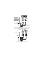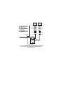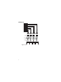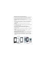
1
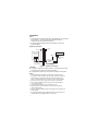
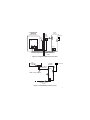
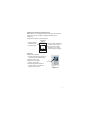
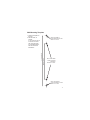
® Doorphone Operating Instructions Model No. KX-T7775 Please read before using the unit, and save for future reference. Introduction Thank you for purchasing the Panasonic KX-T7775 Doorphone. Features: mounts directly on to a wall or can be flush-mounted; illuminated call button; operates standard door-bell; confirmation tone; can make and receive calls; the microphone's sensitivity is adjustable; optional decorative fascias; suitable for home and office use. Compatibility The Panasonic KX-T7775 Doorphone is compatible with the following Panasonic PBX systems: KX-TA1232, KX-TA624, KX-TA308, KX-TD816, KX-TD1232, KX-TDA50, KX-TDA100, KX-TDA200, KX-TAW848, KX-TA824, KX-TD500, KX-T30810, KX-T61610 and KX-T123211. Notes: 1. The KX-T7775 Doorphone is not compatible with KX-TD308 and KX-T336 PBX systems. 2. The KX-T7775 Doorphone cannot be used with a metal gang-box. Accessory Order Information Replacement parts and accessories are available through your local authorized parts distributor. For ordering, call toll free: 1-800-332-5368 2 Part Number Description KX-A401 Fascia - polished brass KX-A402 Fascia - brushed stainless steel QUMH00003Z Interface bracket QUHS00012Z Gasket PSLP1380Z AC Adaptor PSWET7775MU Power Module Specifications Power: AC Adaptor Input/Output: 120 V AC 60 Hz/24 V DC, 300 mA Power Module Input: 24 V DC Output: 17 V at 60 mA DC Doorphone (DP) Input: 17 V at 60 mA DC Cable Diameter/Length: 0.4mm - 210 m (AWG 26 - 689 ft) 2 2 0.5mm - 340 m (AWG 24 - 1115 ft) 2 0.6mm - 500 m (AWG 22 - 1640 ft) Illuminated Button: Yes Surface-mountable: Yes Recess mountable: Yes Connections: Power Module: RJ11 Input Doorphone: from PBX Doorphone Card DC Input Power Supply DC +24 V Terminal Block Output Door 1 to KX-T7775 Terminal Block Input Door 1 Terminal Block Output Doorbell In Doorbell Out Dimensions (H x W x D): 130 mm x 85 mm x 51 mm (51/8" x 33/8" x 2") Weight: 0.4 kg (0.89 lb) Note: Specifications are subject to change. Location Exposure to direct sunlight can result in the discoloration of the Doorphone Unit. The Doorphone Unit can be mounted externally and is weatherresistant, but it should not be subjected to direct contact with water. Maximum operating temperature range is -20°C to +50°C (-4°F to +122°F). When inserting screws avoid pipes and electrical cables, etc, that may be present/buried. 3 Installation Notes: 1. A Doorphone Card must be inserted in the PBX before you can install the Doorphone. This Doorphone manual should be read in conjunction with the relevant PBX manual. 2. If in doubt when installing the Doorphone Module, consult your authorized dealer. System Connection BELL INPUT DOOR CHIME SYSTEM PBX DOORPHONE MODULE AC ADAPTOR Max 500 m (1640 ft) 22 AWG (Refer to Figure 2) PBX DOORPHONE CARD POWER MODULE (Refer to Figure 3) Figure 1 - System Connection CAUTION: This product requires AC input to function. Ensure that the AC outlet is located near the PBX, and is easily accessible. This equipment should only be used with AC Adaptor PSLP1380Z. Notes: 1. The Power Module is designed for internal use only and should be located in close proximity to the main PBX. Wherever possible, it should share any power failure backup systems provided for the PBX. A maximum distance of no more than 10 m (32 ft) is advised. 2. Figures 2 and 3 on page 5 show interconnection in more detail. 3. The connection between the Doorphone and the Power Module is not polarity sensitive. 4. Inputs to the bell contacts must not exceed 24 V AC. 5. This Doorphone manual should be read in conjunction with the relevant PBX manual. 6. Always complete installation before connecting the DC voltage to the Power Module. 7. Low voltage building wiring methods shall meet the requirements of National Electric Code (NEC) NFPA 70, Article 725. 4 POWER MODULE DOORPHONE MODULE REAR OF UNIT BELL INPUT + AC ADAPTOR DOOR CHIME SYSTEM TO PBX DOOR 1 Max 500 m (1640 ft) 22 AWG Figure 2 - Doorphone Module's Interconnects PBX DOORPHONE CARD POWER MODULE Refer to pages 6 to 8 for pin details. AC ADAPTOR 2 3 MODULAR 4 JACK 5 Note: Polarity sensitive. DOOR 1 Max 500 m (1640 ft) 22 AWG Figure 3 - Power Module's Interconnects 5 POWER MODULE 1 KX-TD816/KX-TD1232/ KX-TA1232 (using KX-TD161 DP Interface) and KX-TA308/KX-TA624/ KX-T30810/KX-T61610/ KX-T123211 MODULAR JACK MODULAR JACK MODULAR PLUG MODULAR PLUG TAB UPWARDS TAB UPWARDS 2345 PBX DOORPHONE CARD NOT USED PQJS1T30ZA-E MODULAR JACK POWER MODULE 2 2345 NOT USED NOT USED NOT USED 2 1 4 3 6 Note: Power Module 2 is not available with KX-TA308/KX-T30810/KX-T61610/KX-T123211. 5 Figure 4 - KX-TD816/KX-TD1232/KX-TA1232 (using KX-TD161 DP Interface) and KX-TA308/KX-TA624/KX-T30810/KX-T61610/ KX-T123211: Connection Details POWER MODULE 1 POWER MODULE 2 MODULAR JACK MODULAR JACK KX-TD500 TAB UPWARDS PBX DOORPHONE CARD MODULAR JACK MODULAR PLUG MODULAR PLUG 2345 NOT USED NOT USED TAB UPWARDS 234 5 NOT USED NOT USED PQJS1T30ZA-E 2 1 4 3 6 5 6 Figure 5 - KX-TD500: Connection Details POWER MODULE 1 KX-TD816/KX-TD1232/ KX-TA1232 (using KX-TD160 DP Interface) and KX-TA824/ KX-TAW848/KX-TDA50 MODULAR JACK MODULAR JACK MODULAR PLUG MODULAR PLUG TAB UPWARDS TAB UPWARDS 23 4 5 PBX DOORPHONE CARD MODULAR JACK POWER MODULE 2 NOT USED NOT USED 234 5 NOT USED NOT USED PQJS1T30ZA-E 2 1 4 3 6 5 Figure 6 - KX-TD816/KX-TD1232/KX-TA1232 (using KX-TD160 DP interface) and KX-TA824/KX-TAW848/KX-TDA50: Connection Details 7 543 2 NOT USED NOT USED NOT USED NOT USED 5 4 32 5 4 3 2 NOT USED NOT USED NOT USED NOT USED KX-TDA100 / 200 543 2 TAB UPWARDS MODULAR PLUG MODULAR JACK POWER MODULE 1 POWER MODULE 2 POWER MODULE 3 POWER MODULE 4 Figure 7 - KX-TDA100/200: Connection Details 8 Installing the Panasonic KX-T7775 Doorphone The Panasonic KX-T7775 Doorphone can be surface or flush-mounted. To surface-mount the Panasonic KX-T7775 Doorphone Module: 1. Separate the Doorphone Unit into two halves. 2. Adjust the sensitivity of the Doorphone's microphone, if required (see page 11). 3. Remove the required pop-outs on the back of the Unit and slide the wires through the back of the Unit. Connect to the Doorphone's terminal block. 4. Secure the Unit to the wall using the appropriate screws (not supplied). 5. Re-connect the front panel to the back unit using the supplied 10 mm (3/8") M3 threaded screws. To flush-mount the Panasonic KX-T7775 Doorphone: 1. Separate the Doorphone Unit into two halves. Discard the rear section of the Unit. 2. Adjust the sensitivity of the Doorphone's microphone, if required (see page 11). 3. Attach the gasket to the rear of the interface bracket, as shown in Figure 8. (The gasket side faces the wall.) 4. Gang-box only: Attach the interface bracket to the gang-box using screws (not supplied) (see Figure 9). Recessed only: Attach the interface bracket to the wall using the appropriate screws (this is dependent on the surface structure) (see Figure 10). Refer to the mounting template, on page 15, for drilling positions. Rear View Figure 8 Figure 9 9 5. Feed the wires through the center of the interface bracket and connect the wires to the Doorphone Module. 6. Attach the front of the Doorphone to the bracket using the supplied 10 mm (3/8") M3 threaded screws. Note: The Doorphone can be installed directly into a wall recess without using the interface bracket. Use the mounting template on page 15 for drilling positions. Use the supplied 25 mm (1") screws to fix to the wall (see Figure 11). Figure 10 Figure 11 Note: To ensure the correct fitting of the Doorphone, please do not allow the screw head to protrude more than 3mm (1/8") beyond the interface bracket. 10 Adjusting the Sensitivity of the Microphone Where there is a lot of background noise, for example, due to traffic or machinery, it may be necessary to adjust the sensitivity of the microphone. To adjust the sensitivity of the microphone: Insert flat-headed screwdriver here. Locate the switch. DOORPHONE MODULE REAR OF UNIT + Turn the switch clockwise (-) if sited in a noisy location. Turn the switch counter clockwise (+) for normal noise level (factory setting). Operation Calling from doorphone: 1. Press the call button (see Figure 12). The caller hears confirmation tone. 2. Wait for answer. Talk. Calling from an extension: 1. Pick-up your handset. 2. Dial the Doorphone's extension number, refer to your PBX User Manual for this number. CALL BUTTON Figure 12 11 Important Safety Instructions Safety Requirements When using your telephone equipment, basic safety precautions should always be followed to reduce the risk of fire, electric shock and injury to persons, including the following: Read and understand all instructions. Follow all warnings and instructions marked on the product. Care should be exercised to avoid pinching the wires during installation. Unplug this product from the wall outlet before cleaning. Do not use liquid cleaners or aerosol cleaners. Use a damp cloth for cleaning. 12 Power Module only: Do not use this product near water, for example, near a bathtub, wash bowl, kitchen sink, or laundry tub, in a wet basement, or near a swimming pool. The Doorphone Module is weather-resistant, but should not be subjected to direct water. Slots and openings in the cabinet, at the back or bottom, are provided for ventilation; to protect it from overheating, these openings must not be blocked or covered. The openings should never be blocked by placing the product on a bed, sofa, rug, or other similar surface. This product should never be placed near or over a radiator or other heat source. This product should not be placed in a built-in installation unless proper ventilation is provided. This product should be operated only from the type of power source indicated on the product label. If you are not sure of the type of power supply to your home, consult your dealer or local power company. Do not allow anything to rest on the power cord. Do not locate this product where the cord will be abused by people walking on it. Do not overload wall outlets and extension cords as this can result in the risk of fire or electric shock. Never push objects of any kind into this product through cabinet slots as they may touch dangerous voltage points or short out parts that could result in a risk of fire or electric shock. Never spill liquid of any kind on the product. To reduce the risk of electric shock, do not disassemble this product, but take it to a qualified person when service or repair work is required. Opening or removing covers may expose you to dangerous voltages or other risks. Incorrect reassembly can cause electric shock when the appliance is subsequently used. This unit should be kept free of dust, moisture, high temperatures (more than 50°C (122°F)) and vibration. The socket-outlet shall be installed near the equipment and shall be easily accessible. Unplug this product from the wall outlet and refer servicing to qualified service personnel under the following conditions: When the power supply cord or plug is damaged or frayed. If liquid has been spilled into the product. If the product does not operate normally by following the operating instructions. Adjust only those controls that are covered by the operating instructions because improper adjustment of other controls may result in damage and will often require extensive work by a qualified technician to restore the product to normal operation. If the product has been dropped or the cabinet has been damaged. If the product exhibits a distinct change in performance. Avoid using a telephone (other than a cordless type) during an electrical storm. There may be a remote risk of electric shock from lightning. 13 FCC and Other Information Note: This equipment has been tested and found to comply with the limits for a Class B digital device, pursuant to Part 15 of the FCC Rules. These limits are designed to provide reasonable protection against harmful interference in a residential installation. This equipment generates, uses, and can radiate radio frequency energy and, if not installed and used in accordance with the instructions, may cause harmful interference to radio communications. However, there is no guarantee that interference will not occur in a particular installation. If this equipment does cause harmful interference to radio or television reception, which can be determined by turning the equipment off and on, the user is encouraged to try to correct the interference by one or more of the following measures: Reorient or relocate the receiving antenna. Increase the separation between the equipment and receiver. Connect the equipment into an outlet or a circuit different from that to which the receiver is connected. Consult the dealer or an experienced radio/TV technician for help. This device complies with Part 15 of the FCC Rules. Operation is subject to the following two conditions: (1) This device may not cause harmful interference, and (2) this device must accept any interference received, including interference that may cause undesired operation. CAUTION: Any changes or modifications made to this product not expressly approved by Panasonic Communications Co. Ltd. could void the user's authority to operate the equipment. 14 Wall Mounting Template 1. Place this template on the wall. 2. Drill the holes, as marked. If you mount the unit on a concrete or mortar wall, fit anchor plugs (not included) into the wall with a hammer beforehand. 84 mm (35/16") 116 mm (49/16") DRILL HOLE HERE IF ATTACHING FRONT OF UNIT DIRECTLY TO WALL DRILL HOLES HERE WHEN ATTACHING INTERFACE BRACKET TO WALL DRILL HOLE HERE IF ATTACHING FRONT OF UNIT DIRECTLY TO WALL 15 When you ship the product Carefully pack and send it pre-paid, adequately insured and preferably in the original carton. Attach a postage-paid letter, detailing the symptom, to the outside of the carton. DO NOT send the product to the Executive or Regional Sales offices. They are NOT equipped to make repairs. Product service Panasonic Factory Servicenters for this product are listed in the servicenter directory. Consult your certified Panasonic dealer for detailed instructions. For your future reference Please print, record, and retain the following information for future reference. Note: The serial number of this product can be found on the label affixed to the unit. You should record the model number and the serial number of this unit as a permanent record of your purchase to aid in identification in the event of theft. Model No. KX-T7775 Serial No. Date of Purchase Name of dealer Dealer's address Dealer's Tel. No. Panasonic Consumer Electronics Company, Division of Panasonic Corporation of North America, One Panasonic Way, Secaucus, New Jersey 07094 Panasonic Puerto Rico, Inc., Ave. 65 de Infantería, Km. 9.5, San Gabriel Industrial Park, Carolina, Puerto Rico 00985 http://www.panasonic.com/consumersupport Copyright: This material is copyrighted by Panasonic Communications Co. Ltd., and may be reproduced for internal use only. All other reproduction, in whole or in part, is prohibited without the written consent of Panasonic Communications Co., Ltd. © 2005 Panasonic Communications Co., Ltd. All rights reserved. Printed in the United Kingdom QUQX00152WA KU0505SC0