1
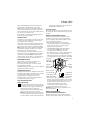
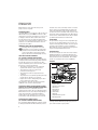
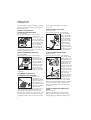
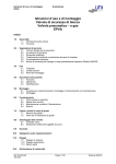
®
KA200
KA210
KA220
KA230
Congratulations!
On the purchase of your
Black & Decker multi sander.
To ensure the best results from your multi
sander please read these safety and usage
instructions carefully.
If you have any questions or queries after
reading this user manual please do not
hesitate to call our Service and Information
Centre, whose number you will find towards
the back of this user manual, or one of our
Authorised Repair Agents. A list of these
Agents and further information is available on
the Internet at www.2helpU.com.
2
Contents
Page 4
Safety instructions
Additonal precautions to take when sanding paint and MDF
Page 5
Personal safety
Environmental safety
Cleaning and disposal
Double insulation
Electrical safety
Mains plug replacement
Page 6
Extension cables
Unwanted tools and the environment
The Black & Decker guarantee
After sales service for your Black & Decker product
Our after sales service policy
Accessories
Technical data
Features
Page 7
Operating your multi sander
Variable speed control
Using your multi sander as a random orbital sander
Fitting the round base
Fitting the sandpaper (round base)
Using your multi sander in the orbital mode
Fitting the pointed base
Page 8
Reversing the pointed base
Fitting the sandpaper (pointed base)
Tip components (pointed base)
Fitting the profile base
Fitting the sanding profile
Fitting the sanding paper (profile base)
Page 9
Removing the side handle
Adjusting the side handle
Dust extraction
Emptying the dustbag
Automatic brake system (ABS)
Handy hints
EC declaration of conformity
Black & Decker phone numbers and addresses
Guarantee card
3
Multi sander user manual
SAFETY INSTRUCTIONS
Warning! When using electric tools, the following
basic safety precautions should always be taken to
reduce the risk of fire, electric shock and personal
injury. Read all these instructions before attempting to
operate the product and save this booklet.
FOR SAFE OPERATION:
• Keep the work area clean. Cluttered areas and
benches invite injuries.
• Consider the work area environment. Do not expose
the power tool to rain and do not use in damp or wet
locations. Keep the work area well lit. Do not use
the power tool where there is a risk to cause fire
or explosion.
• Guard against electric shock. Avoid body contact,
where possible, with earthed or grounded surfaces
(e.g. pipes, radiators, ranges and refrigerators).
• Keep children away. Do not let visitors touch the
tool or extension cord. All visitors should be kept
away from the work area.
• Store idle tools. When not in use, tools should be
stored in a dry, high or locked place, out of reach
of children.
• Do not force the tool. It will do the job better and
more safely at the rate for which it was intended.
• Use the right tool. Do not force small tools or
attachments to do the job of a heavy duty tool.
Do not use the tool for purposes not intended; for
example, do not use a circular saw to cut tree
limbs or logs.
• Dress properly. Do not wear loose clothing or
jewellery as they can be caught in moving parts.
Rubber gloves and non-skid footwear are
recommended when working outdoors. Wear
protective hair covering to contain long hair.
• Use safety glasses. Use a face or dust mask as well,
if the operation is dusty or if the tool is being used in
enclosed spaces.
• Connecting dust extraction equipment. If devices
are provided for the connection of dust extraction
and collection ensure these are connected and
properly used, especially in confined areas.
• Do not abuse the cord. Never carry the tool by its
cord or yank it to disconnect it from the socket. Keep
the cord away from heat, oil and sharp edges.
• Secure the work. Use clamps or a vice to hold the
work. It is safer than using a hand and it frees both
hands to operate the tool.
• Do not overreach. Keep proper footing and balance
at all times.
4
• Maintain the tool with care. Keep a cutting tool
sharp and clean for better and safer performance.
Follow the instructions for lubricating and changing
accessories. Inspect the tools cord periodically and,
if damaged, have repaired by an authorised service
agent. Inspect the extension cord periodically and
replace if damaged. Keep the handles dry, clean and
free from oil and grease.
• Disconnect the tool when not in use, before
servicing and when changing accessories such as
blades, bits and cutters.
• Remove adjusting keys and wrenches. Form the
habit of checking to see that keys and adjusting
wrenches are removed from the tool and replaced in
the storage area before switching on.
• Avoid unintentional starting. Do not carry a
plugged-in tool with a finger on the switch.
Ensure the switch is off when plugging in.
• Use an outdoor extension cord. When a tool is used
outdoors, only use an extension cord intended for
outdoor use and so marked.
• Stay alert. Watch what you are doing, use common
sense and do not operate the tool when tired.
• Check damaged parts. Before further use of the tool,
a guard or other part that is damaged should be
carefully checked to determine whether it will
operate properly and perform its intended function.
Check for alignment of moving parts, free running of
moving parts, breakage of parts, mounting and any
other conditions that may affect its operation.
A guard or other part that is damaged should be
properly repaired or replaced by an authorised
service centre unless otherwise indicated in the
product booklet. Have defective switches replaced
by an authorised service agent. Do not use the tool if
the switch does not turn it on and off.
• Warning! The use of any accessory or attachment,
other than recommended in the product booklet,
may present a risk of personal injury.
• Have the tool repaired by a qualified person. The
electrical tool is in accordance with the relevant safety
requirements. Repairs should only be carried out by
qualified persons using original spare parts, otherwise,
this may result in considerable danger to the user.
ADDITIONAL PRECAUTIONS TO TAKE WHEN SANDING
PAINT AND MEDIUM DENSITY FIBREBOARD (MDF)
Sanding of lead based paint is not recommended due
to the difficulty of controlling the contaminated dust.
The greatest danger of lead poisoning is to children
and pregnant women.
ENGLISH
Any pre-1960 building may have been painted in the
past with paint containing lead, and covered by
additional layers of paint. It is important to determine
whether the paint that is being sanded contains lead
before beginning work. This can be done with lead test
kits or by a professional decorator.
If in doubt, we recommend the following precautions
when sanding any paint or MDF.
PERSONAL SAFETY
No children or pregnant women should enter the work
area where the paint sanding is being done until all
cleaning up has been completed.
A dust mask or respirator should be worn by all persons
entering the work area. The filter should be replaced
daily or whenever the wearer has difficulty breathing.
Note: Only those dust masks suitable for working with
lead paint dust and fumes should be used. Ordinary
paint masks do not offer this protection.
No eating, drinking or smoking should be done in the
work area to prevent ingesting paint particles. Workers
should wash and clean up before eating, drinking or
smoking. Articles of food ,drink etc., should not be left
in the work area where dust could settle on them.
ENVIRONMENTAL SAFETY
Paint should be removed in such a manner as to
minimise the amount of dust generated
Areas where paint removal is occurring should be
sealed with plastic sheeting.
Sanding should be done in a manner to reduce tracking
of paint dust outside the work area.
CLEANING AND DISPOSAL
All surfaces in the work area should be vacuumed and
thoroughly cleaned daily for the duration of the sanding
project. Vacuum filter bags should be changed
frequently. Items of clothing, dust sheets, toys,
washable furniture and utensils should be washed
thoroughly before being used again.
SAVE THESE INSTRUCTIONS!
DOUBLE INSULATION
The tool is double insulated. This means that all
the external metal parts are electrically insulated
from the mains power supply. This is done by
placing insulation barriers between the
electrical and mechanical components making
it unnecessary for the tool to be earthed.
Note: Double insulation does not take the place
of normal safety precautions when operating the
tool. The insulation system is for added protection
against injury resulting from a possible electrical
insulation failure within the tool.
ELECTRICAL SAFETY
Be sure the supply is the same as the voltage given on
the rating plate. The tool is fitted with a two-core cable
and plug.
MAINS PLUG REPLACEMENT (UK ONLY)
Should the mains plug need replacing and you are
competent to do this, proceed as instructed below.
If you are in doubt, contact a Black & Decker service
agent or a qualified electrician.
• Disconnect the plug from the power supply.
• Cut off the plug and dispose of safely. A plug with
bared copper conductors is very dangerous if
engaged in a live socket outlet.
• Only fit BS1363A approved plugs fitted with the
correctly rated fuse. Note: Fuses do not give
personal protection against electric shock.
• The cable wire colours, or a letter, will be marked at
the connection point of most good quality plugs.
Attach the wires to their respective points in the plug
(see diagram). Brown is L (live) and blue is N (neutral).
Fit a plug
approved
to BS1363A
E
Fit a 5 amp fuse
L
N
Connect
blue to
N (neutral)
Make sure that
the outer sheath
of the cable is held
Connect
brown to
L (live)
230 volts AC
only. Never use
firmly by the clamp
a light socket
• Before replacing the top cover of the plug ensure
that the cable restraint is holding the outer sheath of
the cable firmly and that the two leads are correctly
fixed at the terminal screws. If the fuse cover is
missing or damaged do not use the plug.
For replacement or detachable fuse covers,
contact a Black & Decker service agent.
Warning! Never connect live or neutral wires to the
earth pin marked E or
.
MAINS PLUG REPLACEMENT
(AUSTRALIA AND NEW ZEALAND ONLY)
Should the mains plug or cordset of the product be
damaged, it must only be replaced by an authorised
5
ENGLISH
Black & Decker service agent because special
purpose tools are required.
EXTENSION CABLES
Up to 30m (100ft) of 3-core extension cable can be used
without undue loss of power. Note: An extension cable
should not be used unless absolutely necessary. Use of
an improper extension cable could result in a risk of
fire and electric shock. If an extension cable must be
used, make sure it is properly wired, contains the correct
rated fuse as recommended in its literature and is in
good electrical condition.
UNWANTED TOOLS AND THE ENVIRONMENT
Should you find one day that the tool needs
replacement or is of no further use, think of the
protection of the environment. Black & Decker
service agents will accept old tools and will
dispose of them in an environmentally safe way.
THE BLACK & DECKER GUARANTEE
(UK, AUSTRALIA AND NEW ZEALAND ONLY)
If the Black & Decker product becomes defective due
to faulty materials and workmanship, within 24 months
from the date of purchase, we guarantee to either
replace all defective parts or at our discretion, replace
the unit free of charge provided that:
• The product is returned to us or our authorised
repairers with evidence of date of purchase.
• The product has not been used for trade,
professional or hire purposes.
• The product has not been subjected to misuse
or neglect.
• The product has not sustained any damage through
foreign objects, substances or accidents.
• Repairs have not been attempted by anyone other
than our authorised repair agents.
This guarantee is offered as an extra benefit and is
additional to the customers statutory rights.
AFTER SALES SERVICE FOR YOUR BLACK & DECKER
PRODUCT (UK, AUSTRALIA AND NEW ZEALAND ONLY)
Black & Decker offers a nationwide network of
authorised service agents. The use of other than genuine
Black & Decker accessories and parts may damage or
reduce the performance of your Black & Decker
product and may also endanger the user. The terms
and conditions of the warranty may also be effected.
OUR AFTER SALES SERVICE POLICY
(UK, AUSTRALIA AND NEW ZEALAND ONLY)
It is our aim that all Black & Decker customers should
be totally satisfied with their Black & Decker product
6
and after sales service, but if help or advice is needed
please contact your local Black & Decker authorised
repair agent who will be happy to help. Full details of
our after sales service and a list of these agents can be
found on the Internet at www.2helpU.com. Alternatively,
call our Service and Information Centre whose number
you will find towards the back of this manual.
ACCESSORIES
The performance of any power tool is dependant upon
the accessory used. Black & Decker accessories are
engineered to high quality standards and are designed
to enhance the performance of your tool. Buying a
Black & Decker accessory will ensure that you get the
very best from your Black & Decker tool.
TECHNICAL DATA
The level of sound pressure of the tool is in accordance
with EEC legislation. It is recommended that you take
appropriate measures for the protection of your hearing
if the sound level seems uncomfortable. This normally
equates to a sound pressure in excess of 85dB (A).
FEATURES
1
•
2
•
•
7
6
•
8
•
9
•
3
5
4
•
•
1.
2.
3.
4.
5.
6.
7.
8.
9.
On/off switch
Variable speed control
Round base
Pointed base
Profile base
Side handle
Dust bag
Automatic brake system
Sanding profiles
Note: This user manual also covers more than one
catalogue number within this product group. Refer to
your carton for details of your product.
ENGLISH
OPERATING YOUR MULTI SANDER
To switch your multi
sander on, press the
on/off switch on the
side marked “I”.
To switch your multi
sander off, press the
on/off switch on the
side marked “O”.
Before plugging your multi-sander in, make sure it is
switched off.
VARIABLE SPEED CONTROL (KA210E/KA220E/KA230E)
The variable speed
control gives the best
operating performance
for each material. As a
general rule, use low
speed for polishing and
for sanding acrylic/
synthetic materials, and
high speed for wood
and metal.
Material
Variable speed setting
Hardwood (beech)
Softwood (pine)
Veneer wood
Synthetic materials
Acrylic sheet
Non-ferrous metals
Steel
Lacquer and paint removal
Polishing
Rust removal
4-5
4-5
3-5
3-4
1-3
4-5
4-5
4-5
1-3
4-5
USING YOUR MULTI SANDER AS A RANDOM ORBITAL
SANDER (KA200/KA220/KA220E/KA230E)
With the round base
fitted, you can use your
multi sander as a
random orbital sander.
This gives a circular/
orbital movement,
combined with a
rotational movement;
thus giving improved
stock removal and
reduced risk of swirl marks.
FITTING THE ROUND BASE
Disconnect the plug from the electricity supply.
Position the round base
on the spindle.
Position the washer on
the spindle and fit the
screw. Hold the base
and tighten the screw
with the allen key
provided. The base will
wear after some time.
Replacements are
available as an accessory.
FITTING THE SANDPAPER (ROUND BASE)
Disconnect the plug from the electricity supply.
Hold your multi sander
with the base upwards.
Press the sandpaper
disc onto the base,
making sure the base is
completely covered.
It is not necessary to
align the holes in the
paper and the base.
Never use your multi
sander without a sandpaper disc.
USING YOUR MULTI SANDER IN THE ORBITAL MODE
(KA210/KA210E/KA220/KA220E/KA230E)
Detail sanding
Use your multisander with the point of the base
pointing forwards. This position permits you to sand
into difficult or confined areas.
Orbital sanding
Use your multi-sander with the point of the base to the
rear. This permits you to sand large areas with areas
and corners that have easy access.
FITTING THE POINTED BASE
Proceed as follows:
Disconnect the plug from the electricity supply.
Position the pointed
base on the spindle,
making sure the legs of
the base fit into their
housings. The base will
wear after some time.
Replacements are
available as an
accessory. Place the
7
ENGLISH
washer in position on the base and fit the screw using
the allen key provided. Press the base on firmly when
tightening the screw.
REVERSING THE POINTED BASE
(KA210/KA210E/KA220/KA220E/KA230E)
Proceed as follows:
Disconnect the plug from the electricity supply.
Turn the screw
anticlockwise using the
allen key provided in
the handle. Remove the
screw and the washer
from the spindle. Hold
the base in position
with the point facing
rearwards. Fit the washer and the screw. Tighten the
screw using the allen key provided. Press the base on
firmly when tightening the screw.
FITTING THE SANDPAPER (POINTED BASE)
Proceed as follows:
Disconnect the plug from the electricity supply.
Detach the two
diamond-shaped tips
from the main sheet.
Place the sandpaper
on the pointed base,
making sure the holes
of the paper and the
base are aligned.
Never use your multi
sander without sandpaper and always use a full sheet
of sandpaper.
TIP COMPONENTS (POINTED BASE)
(KA210/KA210E/KA220 /KA220E/KA230E)
Each sheet of
sandpaper has a
removable tip, with two
spare tips attached. To
obtain maximum use
from each sheet, detach
and turn the tip when the
front part is worn.
When the whole tip is worn, replace it with one of the
spare tips provided. The tip of the backing pad is
removable. When the front part is worn, turn the tip.
When the tip is completely worn, replace the tip. Spare
tips are available as accessories. When the tip of the
hard plastic tip holder is worn, remove the screw and
8
turn the holder. Spare holders are available as
accessories.
FITTING THE PROFILE BASE (KA230E)
Proceed as follows:
Disconnect the plug from the electricity supply.
Position the profile
base on the spindle,
with the long section
pointing towards the
front of your sander.
Make sure the legs fit
into their housings.
Place the washer in
position on the base
and fit the screw using
the allen key provided.
Press the base on firmly when tightening the screw.
FITTING THE SANDING PROFILE (KA230E)
Proceed as follows:
Disconnect the plug from the electricity supply.
There are six sanding
profiles supplied, each
being different in size
and shape. Select the
sanding profile most
suitable for the task
and push into the slot in
the front of the base.
To do this, first locate
one end of the sanding
profile into the recess
at the back of the
profile base slot, then
push the other end so
that it locates in the
recess in the front of the profile base. The sanding
profile will now be positively located. The sanding
profile can be removed by depressing the small black
square section which is visible at the front of the
profile base, whilst pulling the profile away from its
locating slot.
FITTING THE SANDING PAPER (PROFILE BASE)
(KA230E)
Proceed as follows:
Disconnect the plug from the electricity supply.
With the profile fitted in the base, fit the paper by
applying light pressure making sure that the paper
ENGLISH
follows the shape.
Never use your sander
without sandpaper.
REMOVING THE SIDE HANDLE
Proceed as follows:
Turn the handle anticlockwise and unscrew
completely. Remove the
connecting shoulder.
Unclip the metal clip.
ADJUSTING THE SIDE HANDLE
Proceed as follows:
Loosen the handle
slightly. Move the metal
clip around the body of
the sander until the
side handle is in the
desired position.
Tighten the handle.
DUST EXTRACTION SYSTEM
Most of the dust from the work surface is collected in
the dustbag. The extraction fan of your multi sander
draws the dust from the surface through the holes in
the base. The dust then passes through the fan shroud
to the dustbag. You can also use your multi sander with
a vacuum cleaner. A special adaptor is available from
Black & Decker as an accessory.
EMPTYING THE DUSTBAG
Disconnect the plug from the electricity supply.
Hold your multi sander
vertically with the
dustbag facing
downwards. Squeeze
the sides of the dustbag
together, adjacent to
the finger grips and pull
the bag gently. Empty
the dustbag and
replace on the sander.
A click is heard when the dustbag is correctly fitted.
The plastic baffle is removable. However, it is not
necessary to remove the baffle when emptying the
dustbag. Do not wash the dustbag. Empty the dustbag
every 10 minutes.
AUTOMATIC BRAKE SYSTEM (ABS)
(KA200/KA220/KA220E/KA230E)
Your multi sander has an automatic brake system
(ABS). This feature gives you optimal control as it
keeps the speed of the disc below that of the motor
when your sander is not on the work surface. When
your sander is switched off, the disc stops very quickly.
HANDY HINTS
You can hold your
multi sander in various
positions for maximum
comfort but make sure
you do not block the air
intake slots.
• Do not apply excessive pressure when you use your
multi sander, especially in the random orbit mode.
• Replace the sandpaper when it is worn.
• Use high grit sandpaper for a fine finish. As a
general rule, start with coarse grits and gradually
change to the finer grits for the final finish.
• When using your multi sander to sand profiles be
sure to keep the profile square to the workpiece.
• Smaller radii sanding profiles work better with finer
grit sandpaper.
• Ensure that the platen is flat on the work surface
whilst sanding.
EC DECLARATION OF CONFORMITY
We declare that units:
KA200, KA210, KA210E, KA220, KA220E, KA230E
conform to 89/392/EEC, 89/336/EEC, EN55014,
73/23/EEC, EN55104, EN50144
A weighted sound pressure 77.1dB (A)
9
ENGLISH
A weighted sound power 90.1dB (A)
Hand/arm weighted vibration <2.5m/s2
Brian Cooke - Director of Engineering
Black & Decker Ltd, Spennymoor, County Durham
DL16 6JG United Kingdom
The Black & Decker policy is one of continuous
improvement to our product and as such we reserve
the right to change the product specification without
prior notice.
10
Australia
DeWalt Industrial Power Tool Company
(Distributors of Black & Decker products)
7 Clarice Road, Box Hill, Victoria 3128
Tel: 03 9895 9200
Fax: 03 9899 7465
New Zealand
Black & Decker
483 Great South Road
Penrose, Auckland
Tel: 09 579 7600
Fax: 09 579 8200
South Africa
Black & Decker South Africa (Pty) Ltd
Suite no 107, PostNet X65
Halfway House 1685
Tel: 011 314 4431
Fax: 011 314 4435
United Kingdom
Black & Decker
210 Bath Road, Slough
Berkshire SL1 3YD
Tel: 01753 574277
Tlx: 848317 BAND MH
Fax: 01753 551155
Part no: 375614 2/99.4
11
Data protection act: Tick this box if you prefer not to receive
information from Black & Decker or other companies.
Product catalogue number: KA2_ _ / _ _ _
Country:
Postcode:
County or state:
Town:
House number or name and street:
Name:
Address of the dealer where your multi sander was purchased:
Yes
No
Address of the dealer where your multi sander was purchased:
What was the price of your multi sander?
Was your multi sander bought as a replacement?
Was your multi sander your first purchase?
Was your multi sander a gift?
Date of your purchase:
GUARANTEE CARD FOR THE UK, IRELAND AND SOUTH AFRICA
South Africa: Black & Decker South Africa (Pty) Ltd, Suite no 107, PostNet X65, Halfway House 1685
United Kingdom & Ireland: PO Box 821, Slough, Berkshire, SL1 3AR
Please complete this section immediately after the purchase of your multi-sander
and post it to the Black & Decker address in your country (above).
Part no: 375614 2/99.4