1
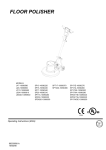
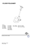
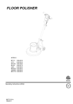
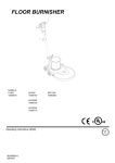
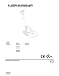
FLOOR POLISHER
MODELS:
U17-10090580
U20-10090600
U17X-10090590
U20X-10090610
UDS20-10090630
SP13-10090220
SP15-10090230
SP17-10090240
SP20-10090310
SP17X-10090280
SP20X-10090320
SPDS20-10090350
SPT17-10090370
SPT20X-10090380
SP17IE-10090270
SP17IA-10090260
SP17XIE-10090300
SP17XIA-10090290
SPDS17IE-10090340
SPDS17IA-10090330
SP17HDIE-10090250
IPX4
Operating Instructions (ENG)
86309580-A
10/08/08
Downloaded from www.Manualslib.com manuals search engine
MACHINE DATA LOG/OVERVIEW
Model:
Date of Purchase:
Serial Number:
Sales Representative:
Address:
Phone Number:
2
86309580 FLOOR POLISHER 10/08/08
Downloaded from www.Manualslib.com manuals search engine
TABLE OF CONTENTS
Machine Data Log.............................2
Table of Contents..............................3
HOW TO USE THIS MANUAL
How to use this Manual.....................1-1
SAFETY
Important Safety Instructions ............2-1
Hazard Intensity Level. .....................2-2
Grounding Instructions 120V. ...........2-3
Grounding Instructions 230V ............2-4
Safety Label Location .......................2-5
OPERATION
Technical Specifications ...................3-1
Handle Installation ............................3-2
Controls.............................................3-3
Handle Adjustment............................3-3
Machine Operation............................3-4
Pad Driver Installation.......................3-4
MAINTENANCE
Scrub Brush/Pads .............................4-1
Machine Troubleshooting..................4-2
GROUP PARTS LIST
Brush/Pad Driver Group....................5-1
Electrical – 120v................................5-3
Electrical – 230v................................5-5
Deck..................................................5-7
Handle...............................................5-9
Motor.................................................5-11
Wiring-120V ......................................5-13
Wiring-230V ......................................5-15
Suggested Spare Parts.....................5-14
86309580 FLOOR POLISHER 10/08/08
Downloaded from www.Manualslib.com manuals search engine
3
HOW TO USE THIS MANUAL
This manual contains the following sections:
-
HOW TO USE THIS MANUAL
SAFETY
OPERATIONS
MAINTENANCE
PARTS LIST
The HOW TO USE THIS MANUAL section will tell
you how to find important information for ordering
correct repair parts.
Parts may be ordered from authorized dealers.
When placing an order for parts, the machine
model and machine serial number are important.
Refer to the MACHINE DATA box which is filled
out during the installation of your machine. The
MACHINE DATA box is located on the inside of
the front cover of this manual.
The OPERATIONS section is to familiarize the
operator with the operation and function of the
machine.
The MAINTENANCE section contains preventive
maintenance to keep the machine and its
components in good working condition. They are
listed in this general order:
The PARTS LIST section contains assembled
parts illustrations and corresponding parts list. The
parts lists include a number of columns of
information:
-
The SAFETY section contains important
information regarding hazard or unsafe practices
of the machine. Levels of hazards are identified
that could result in product or personal injury, or
severe injury resulting in death.
-
REF – column refers to the reference
number on the parts illustration.
PART NO. – column lists the part
number for the part.
PRV NO. - Reference No.
QTY – column lists the quantity of the
part used in that area of the machine.
DESCRIPTION – column is a brief
description of the part.
SERIAL NO. FROM – If this column
has an (*) and a Reference number,
see the SERIAL NUMBERS page in
the back of your manual. If column
has two asterisk (**), call manufacturer
for serial number. The serial number
indicates the first machine the part
number is applicable to. The main
illustration shows the most current
design of the machine. When a boxed
illustration is shown, it displays the
older design.
NOTES – column for information not
noted by the other columns.
NOTE: If a service or option kit is installed on your
machine, be sure to keep the KIT INSTRUCTIONS
which came with the kit. It contains replacement
parts numbers needed for ordering future parts.
NOTE: The number on the lower left corner of the
front cover is the part number for this manual.
1-1
86309580 FLOOR POLISHER 10/08/08
Downloaded from www.Manualslib.com manuals search engine
SAFETY
IMPORTANT SAFETY INSTRUCTIONS
When using an electrical appliance, basic precaution
must always be followed, including the following:
READ ALL INSTRUCTIONS BEFORE USING THIS MACHINE.
To reduce the risk of fire, electric shock, or injury:
Use only indoors. Do not use outdoors or expose to rain.
Use only as described in this manual. Use only manufacturer’s recommended components and attachments.
If the machine is not working properly, has been dropped, damaged, left outdoors, or dropped into water,
return it to an authorized service center.
Do not operate the machine with any openings blocked. Keep openings free of debris that may reduce
airflow.
Machine can cause a fire when operating near flammable vapors or materials. Do not operate this machine
near flammable fluids, dust or vapors.
This machine is suitable for commercial use, for example in hotels, schools, hospitals, factories,
shops and offices for more than normal housekeeping purposes.
Maintenance and repairs must be done by qualified personnel.
During operation, attention shall be paid to other persons, especially children.
The machine shall only be operated by instructed and authorized persons.
When leaving unattended, unplug the machine.
Do not handle the plug or machine with wet hands.
Do not unplug machine by pulling on cord. To unplug, grasp the plug, not the cord.
Do not use with damaged cord or plug. Follow all instructions in this manual concerning grounding the
machine.
Do not pull or carry by cord, use cord as a handle, close a door on cord, or pull cord around sharp edges or
corners.
Do not pull/run machine over cord. Keep cord away from heated surfaces.
Connect to a properly grounded outlet. See Grounding Instructions.
SAVE THESE INSTRUCTIONS
86309580 FLOOR POLISHER 10/08/08
Downloaded from www.Manualslib.com manuals search engine
2-1
SAFETY
The following symbols are used throughout this guide as indicated in their descriptions:
HAZARD INTENSITY LEVEL
There are three levels of hazard intensity identified by signal words – WARNING and CAUTION and
FOR SAFTEY. The level of hazard intensity is determined by the following definitions:
WARNING – Hazards or unsafe practices which COULD result in severe
personal injury or death.
CAUTION – Hazards or unsafe practices which could result in minor personal
injury or product or property damage.
FOR SAFETY: To identify actions which must be followed for safe operation of equipment.
Report machine damage or faulty operation immediately. Do not use the machine if it is not in proper
operating condition. Following is information that signals some potentially dangerous conditions to the
operator or equipment. Read this information carefully. Know when these conditions can exist. Locate
all safety devices on the devices on the machine. Please take the necessary steps to train the machine
operating personnel.
FOR SAFETY:
DO NOT OPERATE MACHINE:
Unless Trained and Authorized.
Unless Operation Guide is Read and Understood.
In Flammable or Explosive areas.
In areas with possible falling objects.
WHEN SERVICING MACHINE:
Avoid moving parts. Do not wear loose fitting clothing, jackets, shirts, or sleeves when working
on the machine. Use approved replacement parts.
2-2
86309580 FLOOR POLISHER 10/08/08
Downloaded from www.Manualslib.com manuals search engine
SAFETY
GROUNDING INSTUCTIONS-120V
Grounding Pin
THIS PRODUCT IS FOR COMMERCIAL USE
ONLY.
ELECTRICAL:
In the USA this machine operates on a one 15
amp nominal 120V, 60 hz, A.C. power circuit. The
amp, hertz, and voltage are listed on the data label
found on each machine. Using voltages above or
below those indicated on the data label will cause
serious damage to the motors.
GROUNDING CONNECTION
USING AN ADAPTOR
Grounded
Outlet
FIGURE A
Tab for Grounding
Screw
Metal Screw
Adaptor
Grounded
Outlet Box
FIGURE B
Adaptor
GROUNDING INSTRUCTIONS:
This appliance must be grounded. If it should
malfunction or break down, grounding provides a
path of least resistance for electric current to
reduce the risk of electric shock. This appliance is
equipped with a cord having an equipmentgrounding conductor and grounding plug. The
plug must be inserted into an appropriate outlet
that is properly installed and grounded in
accordance with all local codes and ordinances.
This appliance is for use on a nominal 120-volt
circuit, and has a grounded plug that looks like the
plug in “Fig. A”. A temporary adaptor that looks
like the adaptor in “Fig . C” may be used to
connect this plug to a 2-pole receptacle as shown
in “Fig. B”, if a properly grounded outlet is not
available. The temporary adaptor should be used
only until a properly grounded outlet (Fig. A) can
be installed by a qualified electrician. The green
colored rigid ear, lug, or the like extending from
the adaptor must be connected to a permanent
ground such as a properly grounded outlet box
cover. Whenever the adaptor is used, it must be
held in place by a metal screw.
FIGURE C
Note: Adaptors are not allowed in Canada.
Improper connection of the equipmentgrounding conductor can result in a risk of
electric shock. Check with a qualified
electrician or service person if you are in doubt
as to whether the outlet is properly grounded.
Do not modify the plug provided with the
appliance - if it will not fit the outlet, have a
proper outlet installed by a qualified
electrician.
86309580 FLOOR POLISHER 10/08/08
Downloaded from www.Manualslib.com manuals search engine
2-3
SAFETY
GROUNDING INSTRUCTIONS-230V
THIS PRODUCT IS FOR COMMERCIAL USE
ONLY.
ELECTRICAL:
The amp, hertz, and voltage are listed on the
data label found on each machine. Using
voltages above or below those indicated on the
data label will cause serious damage to the
motors.
EXTENSION CORDS:
If an extension cord is used, the wire size must
be at least one size larger than the power cord
on the machine, and must be limited to 50 feet
(15.5m) in length.
GROUNDING INSTRUCTIONS:
This appliance must be grounded. If it should
malfunction or break down, grounding
provides a path of least resistance for electric
current to reduce the risk of electric shock.
This appliance is equipped with a cord having
an equipment-grounding conductor and
grounding plug. The plug must be inserted
into an appropriate outlet that is properly
installed and grounded in accordance with all
local codes and ordinances.
Improper connection of the equipment-grounding
conductor can result in a risk of electric shock.
Check with a qualified electrician or service person
if you are in doubt as to whether the outlet is
properly grounded. Do not modify the plug
provided with the appliance - if it will not fit the
outlet, have a proper outlet installed by a qualified
electrician.
2-4
86309580 FLOOR POLISHER 10/08/08
Downloaded from www.Manualslib.com manuals search engine
SAFETY
SAFETY LABEL LOCATION
NOTE: These drawings indicate the location of safety labels on the Machine. If, at any time,
the labels become illegible contact your authorized representative for prompt replacement.
WARNING LABEL
P/N 86219740
PRV NO. 500194
86309580 FLOOR POLISHER 10/08/08
Downloaded from www.Manualslib.com manuals search engine
2-5
TECHNICAL SPECIFICATIONS
ITEM
DIMENSION/CAPACITY/MODEL
Heavy-duty die cast aluminum deck with heavyduty rubber bumper, tubular steel adjustable
handle with die cast aluminum handle housing
CONSTRUCTION
MOTOR
1HP 115V induction
1.5HP 115V induction
1.75 HP 115V 175/300RPM
1HP 230V induction
1.5 HP 230V induction
1.75 HP 230V 175/300RPM
BRUSH/PAD SPEED
SP13, SP15, SP17, U17, SP17, SP20, U20
SP17X, U17X, SPT20X, SP20X, U20X
SPDS20, UDS20
SP17IA, SP17IE
SP17HDIE, SP17XIA, SP17XIE
SPDS17IA, SPDS17IE
SP13, SP15, SP17, U17, SP17, SP20, U20,
SP17X, U17X, SPT20X, SP20X, U20X
SP17HDIE , SP17IA, SP17IE, SP17XIA,
SP17XIE
UDS20, SPDS20, SPDS17IA, SPDS17IE
175 rpm
146 rpm 230V
175/300 rpm
ELECTRICAL SYSTEM
SP13, SP15,, SP17, U17,SPT17, SP17X, U17X,
SP20, U20, SPT20X, SP20X, U20X,
SPDS20, USD20
SP17HDIE, SP17XIA, SPX17IE, SPDS17IE,
SP17IA, SP17XIA, SPDS17IA
115 volts, 60 Hz
230 volts, 50Hz
CABLE
50’ (15 m), 14/3, built in cord wrap
75’ (22.9) 1.5mm³, built in cord wrap
SWITCHES
WHEELS
HANDLE
SP13, SP15,, SP17, U17,SPT17, SP17X, U17X,
SP20, U20, SPT20X, SP20X, U20X,
SPDS20, USD20
SP17HDIE, SP17XIA, SPX17IE, SPDS17IE,
SP17IA, SP17XIA, SPDS17IA
Dual levers with safety lock
Two 5” (12.7 cm) dia., 1.25” (3 cm) wide, nonmarking tread
1.5” (4 cm) tubular steel, adjustable, easy to use
thumb activated safety lock
DIMENSIONS (L X W X H)
13” (33 cm) model
15” (38 cm) model
17” (43 cm) model
20” (51 cm) model
3-1
21.0” (53 cm) x 14” (36 cm) x 47” (119 cm)
22.0” (56 cm) x 16” (41 cm) x 47” (119 cm)
23.0” (58 cm) x 18” (46 cm) x 47” (119 cm)
24.5” (62 cm) x 21” (53 cm) x 47” (119 cm)
86309580 FLOOR POLISHER 10/08/08
Downloaded from www.Manualslib.com manuals search engine
HANDLE INSTALLATION
WHEN INSTALLING THE HANDLE
ASSEMBLY, CHECK ORIENTATION OF
THE CORD ASM AND CORD HOOK.
4
MOTOR PLUG
RECEPTACLE
5
6
MOTOR
PLUG
DECK
ASSEMBLY
PIVOT
HOLE
3
2
1
(SEE NOTE)
The handle must be installed by qualified personnel. Read all instructions
thoroughly. The machine is shipped with handle unassembled.
The machine is shipped with handle unassembled.
Follow these steps for installation:
1. Remove handle and deck assembly from carton.
2. Attach handle assembly to base using hardware kit (86219680-PRV NO. 47331) (attached to handle in a
plastic bag) items 1, 2, and 3.
NOTE: The spacers (items 1) are required for the correct operation of the handle. The spacers are
positioned completely inside the pivot holes in the casting, and are held in place by tightening the
bolts and washers (items 2 and 3) against the spacer.
3. Remove bolt, nut and washers (items 4, 5 and 6) from lower block on handle assembly. Attach links as
shown. Tighten bolt and nut securely, then back off 1/4 to 1/2 turn.
4. Check handle for movement up and down.
5. Plug motor cord into handle cord receptacle.
86309580 FLOOR POLISHER 10/08/08
Downloaded from www.Manualslib.com manuals search engine
3-2
OPERATION
CONTROLS
1. Safety Lock – Prevents unintended operation
of the machine.
2. Switch Levers – Turns machine on/off.
3. Adjustment Handle – Allows the handle to be
adjusted to a comfortable operating position.
1
NOTE: It is incorrect to make it lock
opposite from the way it was assembled by
applying more force to the nut.
The pivot pin is off center in relationship to the
axis of the handle. To adjust handle, tighten
nut on handle while in the locked position. The
handle is locked when the screw is to the
outside of the machine and the flat on the
opposite side of the handle is flush to the
bracket.
PIVOT PIN
HANDLE
2
2
LOCKING SIDE FLAT
3
HANDLE HEIGHT ADJUSTMENT
NOTE: The handle is in the up, locked
position from the factory.
1
3
2
4
The handle adjust bar (1) for the polishers are
individually preset at the factory for optimum
locking efficiency and minimum effort of
engaging. It should not be necessary to adjust
the handle adjust bar unless the handle
adjustment bar (1) the washer (3) and nut (2)
have been disturbed.
3-3
86309580 FLOOR POLISHER 10/08/08
Downloaded from www.Manualslib.com manuals search engine
OPERATION
MACHINE OPERATION
DAILY MAINTENANCE
1. Inspect power cord for wear. To prevent
electrical shock replace cords with frayed or
cracked insulation immediately.
For indoor use only.
2. Place machine in the storage position.
When using the pad, always keep the machine
moving when in contact with the floor.
3. Check pad condition. Change if soiled or torn.
PAD INSTALLATION
1. Lay machine back, exposing the under side.
High starting torque. Hold machine firmly with
both hands.
1. Ensure that the pad driver is in good shape.
Install or change pad if necessary.
2. Plug the machine into a wall outlet as
described in the grounding instructions.
3. Lower the handle by unlocking the adjustment
handle and moving the handle into position.
Relock the handle when it is in a comfortable
position.
Insure that handle is locked in position before
starting machine.
4. Push the safety lock forward, unlocking the
switch levers.
5. With the safety lock forward, squeeze one or
both of the switch levers, turning the machine
on. (These levers can be operated
independently of each other). The safety lock
will not re-engage until both levers are
released.
Ensure pad is centered on pad driver. Pull pad to
edge of pad driver in several directions to check
for proper engagement.
NOTE: Use care when replacing center lock to
prevent cross threading.
6. To stop the machine, release the switch
levers.
7. Do not let machine rest on pad. When
finished with the machine, return handle to the
storage position.
NOTE: The machine is equipped with a circuit
breaker to protect the motor in the event an
overload condition occurs. The circuit breaker
is located on the handle. Push the reset button
to restart the machine. If the breaker trips
again, correct the cause of overloading before
proceeding.
86309580 FLOOR POLISHER 10/08/08
Downloaded from www.Manualslib.com manuals search engine
3-4
NOTES:
3-5
86309580 FLOOR POLISHER 10/08/08
Downloaded from www.Manualslib.com manuals search engine
MAINTENANCE
SCRUB BRUSHES
FINISHED FLOORS
NOTE: All original equipment brushes are
equipped with “Perform Alert©”. This feature will
tell the operator when it is time to replace the
scrub brushes. “Perform Alert©” brushes have
pre-trimmed bright yellow tufts to indicate the
length of a worn out brush. When the tufts in the
scrub brush wear to a length equal to the yellow
tufts, the scrub brushes should be replaced.
Nylon Polish is the softest brush. It will gently
clean finished tile or terrazzo floors without
removing floor finish or floor material. Used for
washing highly polished or burnished floors.
There are five different types of brushes available
to cover applications from cleaning heavily soiled
floors to polishing. A pad driver is also available to
take advantage of the many cleaning pads on the
market and further add to the flexibility of the
machine.
Please refer to the following to assist in selecting
the proper brush or pad for the work at hand.
UNCOATED FLOORS
Aggressive Grit is a nylon fiber impregnated with
silicone carbide grit. It grinds away stain, soil, and
removes surface material.
Mild Grit is a less aggressive silicone carbide grit
suitable for cleaning medium soil conditions.
Advantages are faster ground speed than nylon
bristles on light solid applications.
Nylon is a general-purpose scrub brush with stiff
bristles. Polypropylene works well for maintaining
concrete, wood and tile floors.
Nylon bristles are used in a variety of applications
on coated or uncoated surfaces.
White Pads (Polishing) are used for dry polishing
to achieve a high-gloss appearance, or surface
washing on highly polished or burnished floors.
Red Pads (Buffing) are used for light-duty
scrubbing. When used with a mild detergent they
will provide surface cleaning without removing the
finish.
Blue Pads (Scrubbing) are used for heavy-duty
scrubbing and light stripping. The blue pads
remove less finish than brown stripping pads, yet
will remove black marks, stains and dirt.
Brown Pads (Stripping) are used for easy and
complete removal of old floor waxes/finishes.
They will quickly remove ground in dirt, black heel
marks, and spills. When used with the proper
stripper, this pad leaves the floor clean and ready
for finishing.
The scrub brushes should be checked before each
days work for wire, string, wear and damage. The
scrub brushes should be replaced if brush bristles
are missing or if yellow Perform Alert © indicates
minimum brush length.
SERVICE SCHEDULE
MAINTENANCE
Check pad wear to prevent buildup of chemicals
Check pad driver system for damage
Check handles, switches, and knobs for damage
Store with pad off the floor
Check all bearings for noise
Check skirt/bumpers for damage and replace as necessary
Check overall performance of machine
86309580 FLOOR POLISHER 10/08/08
Downloaded from www.Manualslib.com manuals search engine
DAILY
MONTHLY
*
*
*
*
*
*
*
4-1
MACHINE TROUBLESHOOTING
PROBLEM
Machine will not run
CAUSE
Circuit breaker tripped in
building.
Power switch failure
Tripped circuit breaker
Faulty power cord
Fuse in motor blown
(Dual speed only)
Electrical shock
Equipment not grounded
Receptacle not grounded
Internal wiring problem
Repeated circuit breaker
tripping
Mechanical problem
Faulty circuit breaker
Excessive vibration
Pad does not turn but motor is
running
4-2
Downloaded from www.Manualslib.com manuals search engine
Pad not centered
Damaged or unevenly worn
pad
Damaged pad driver
Sheer coupling has failed
SOLUTION
Check and reset.
Test switch for continuity and
replace if necessary.
Reset.
Replace.
Replace
CAUTION: To reduce the risk
of electrical shock, unplug the
machine before opening fuse
holder. Fuse will only open
under extreme conditions.
Investigate cause before
replacing.
Follow grounding instructions
exactly.
Have an electrician inspects
building’s wiring.
Ensure that the machine wiring
matches the appropriate wiring
diagram. Replace any wires or
components that are short
circuiting.
Higher amp draws indicate a
mechanical problem. Find the
problem before using the
machine.
Test circuit for continuity.
Replace circuit breaker if
necessary.
Re-center pad.
Replace pad. Do not rest
machine on pad when not in
use.
Replace.
Replace coupling.
86309580 FLOOR POLISHER 10/08/08
NOTES:
86309580 FLOOR POLISHER 10/08/08
Downloaded from www.Manualslib.com manuals search engine
4-3
BRUSH/PAD DRIVER
3
3
1
1A-1E
2A-2W
5-1
86309580 FLOOR POLISHER 10/08/08
Downloaded from www.Manualslib.com manuals search engine
BRUSH/PAD DRIVER
REF
PART NO.
PRV NO.
QTY
DESCRIPTION
1A
1B
1C
1D
1E
2A
86284280
86284330
86000120
86284290
86284300
86283720
02216
02396
02218
02217
02219
02232
-
2B
86283730
02233
-
2C
86283740
02234
-
PAD DRIVER, 13" POLISHER
PAD DRIVER, 15" POLISHER
PAD DRIVER, 17" POLISHER
PAD DRIVER, 19” HS
PAD DRIVER, 20" POLISHER
BRUSH, 13" NYL.POL. W/CLT.PLT
BRUSH, 13" NYL.SCRUB
W/CLT.PLT
BRUSH, 13" MILD GRIT W/CLT.PLT
BRUSH, 13" AGG. GRIT
W/CLT.PLT
BRUSH, 13" POLYPRO W/CLT. PLT
BRUSH, 15” NYL.POL. W/CLT.PLT
BRUSH, 15” NYL. SCRUB
W/CLT.PLT
BRUSH, 15” MILD GRIT W/CLT.PLT
BRUSH, 15” AGG.GRIT W/CLT.PLT
BRUSH, 15” PLOYPRO W/CLT.PLT
BRUSH, 17" NYL. POL. W/CLT.PLT
BRUSH, 17" NYL.SCRUB
W/CLT.PLT
BRUSH, 17" MILD GRIT W/CLT.PLT
BRUSH, 17" AGG. MALGRIT W/C.P
BRUSH, 17" POLYPRO W/CLT. PLT
BRUSH, 20"
NYL.POL.W/CLT.PLT.SFT
BRUSH, 20” NYL.SCRUB
W/CLT.PLT
BRUSH, 20" MILD GRIT W/CLT.PLT
BRUSH, 20" AGG. MALGRIT
W/C.P.
BRUSH, 18" POLYPRO W/CLT. PLT
PLATE, PAD CLUTCH
02235
-
2E
2F
86283750
86283760
86230480
02236
02447
-
2G
86230490
02448
-
2H
2J
2K
2L
86230460
86230450
86230470
86000140
02445
02444
02446
02242
-
2M
86283800
02240
-
2N
2P
2Q
86000130
86283710
86000110
02241
02205
02206
-
2R
86283790
02239
-
2T
86283770
02237
-
2U
86283780
02238
-
2V
86283690
02202
-
2W
3
86283700
86284350
02203
02220
-
2D
86309580 FLOOR POLISHER 10/08/08
Downloaded from www.Manualslib.com manuals search engine
SERIAL NO.
FROM
NOTES:
5-2
ELECTRICAL-120V
8
9
7
11
6
14 A-C
5
10
2
1
3
13
12
4
5-3
86309580 FLOOR POLISHER 10/08/08
Downloaded from www.Manualslib.com manuals search engine
ELECTRICAL-120V
REF PART NO. PRV NO. QTY
1
2
3
4
5
6
7
8
9
10
11
12
13
86002010
86198450
86234150
86216920
86268450
86136780
86007110
86224750
86137290
86137330
86215140
86224930
86224300
DESCRIPTION
SERIAL NO.
FROM
NOTES
14942
20005
23167
23206
70689
70801
72123
73993
87057
87208
140674
730012
730021
1
1
1
1
1
2
2
1
2
1
1
1
1
BOOT, 3/8 CIRCUIT BREAKER
CLAMP, 5/16 NYLON
CORD SET, 14/3 ST X 50FT, YLW
CORDSET, 14/3 X 52 IN, SJT, BLK
SCR, M4.8 X 10 HHTF TYPE B
SCR, M3.5 X 40 PHTF
SWITCH, 25A SPST 125-250V SNAP
SPRING, COMP, .48OD X .91
WASHER, M4 LOCK
WASHER, M5 LOCK
BARRIER SHEET
STRAIN RELIEF, 14/3 STRAIGHT
SPACER, POLISHER HANDLE
14A 86291460
-
1
BREAKER, 11A VDE CIRCUIT
SP13, SP15, SP17,
U17, SPT17, SP20,
U20
14B 86312500
-
1
BREAKER, CIRCUIT, 13A VDE
SP17X, U17X,
SPT20X, SP20X,
U20X
14C 86312460
-
1
BREAKER, 14A, VDE CIRCUIT
SPDS20, UDS20
86309580 FLOOR POLISHER 10/08/08
Downloaded from www.Manualslib.com manuals search engine
5-4
ELECTRICAL-230V
8
9
7
11
6
14 A-C
5
10
2
1
3 A-B
13
12
4
5-5
86309580 FLOOR POLISHER 10/08/08
Downloaded from www.Manualslib.com manuals search engine
ELECTRICAL-230V
REF PART NO.
PRV NO.
QTY
1
1
DESCRIPTION
SERIAL NO.
NOTES
FROM
1
2
86002010
86198450
14942
20005
BOOT, 3/8 CIRCUIT BREAKER
CLAMP, 5/16 NYLON
3A
86216950
23212
CORD SET, EURO 1.5MM X 75
BLK
SP17HDIE,
SP17IE, SPX17IE,
SPDS17IE
3B
86216970
23217
CORD SET, SAA33 1.5MM X 75
SP17IA, SP17XIA,
SPDS17IA
4
5
6
7
8
9
10
11
12
13
86216920
86268450
86136780
86007110
86224750
86137290
86137330
86215140
86224930
86224300
23206
70689
70801
72123
73993
87057
87208
140674
730012
730021
1
1
2
2
1
2
1
1
1
1
CORDSET, 14/3 X 52 IN, SJT, BLK
SCR, M4.8 X 10 HHTF TYPE B
SCR, M3.5 X 40 PHTF
SWITCH, 25A SPST 125-250V
SPRING, COMP, .48OD X .91
WASHER, M4 LOCK
WASHER, M5 LOCK
BARRIER SHEET
STRAIN RELIEF, 14/3 STRAIGHT
SPACER, POLISHER HANDLE
14A 86312470
-
1
BREAKER, 3A, VDE CIRCUIT
14B 86215710
141046
1
BREAKER, 5A VDE CIRCUIT
14C 86312530
-
1
BREAKER, CIRCUIT 10A, VDE
86309580 FLOOR POLISHER 10/08/08
Downloaded from www.Manualslib.com manuals search engine
SP17IA, SP17IE
SP17HDIE,
SP17XIA, SP17XIE
SPDS17IA,
SPDS17IE
5-6
DECK
9A-9F
1
4
12
10
13
6
11
2A-2D
7
5
3 14
5-7
8
86309580 FLOOR POLISHER 10/08/08/08
Downloaded from www.Manualslib.com manuals search engine
DECK
REF PART NO. PRV NO. QTY
DESCRIPTION
1 86214930
2A 86216350
2B 86216330
03111
14373
14371
1
1
-
AXLE, MAIN POLISHER
BUMPER, EXTRUSION 53.4 IN.
BUMPER, EXTRUSION 37.3”
2C 86216340
14372
-
BUMPER, EXTRUSION 43.8"
2D 86216350
14373
-
BUMPER, EXTRUSION 53.4"
3
4
5
6
7
8
9A
9B
27871
51328
57220
57276
70262
70691
29211
29212
2
2
2
2
2
2
1
1
CAP, EXTRUSION
LINK, HANDLE ADJUST
NUT, M6 X 1 NYLOCK
NUT, PUSH FLAT RD .51 ID
SCR, M8-1.25 X 20 HHMS PLTD
SCR, M6 X 25 HHCS
DECK, 13 IN POLISHER, BLUE
DECK, 15 IN POLISHER, BLUE
86216600
86221860
86271550
86222270
86133340
86276570
86288430
86288440
9C 86217600
9D
9E
9F
10
11
12
13
14
29213
86288960 29213GRY
86217620 29214BLU
86288970 29214GRY
86288740
70709
86137280
87054
86226020
89206
86225720
87203
86137340
87211
1
DECK, 17 IN POLISHER, BLUE
1
1
1
1
2
2
2
2
DECK, 17 IN POLISHER, GRAY
DECK, 20 IN POLISHER BLUE
DECK, 20 IN POLISHER, GRAY
SET SCR, 8MMX1.25X8MM CUP PT
WASHER, M8 FLAT DIN125A PLT
WHEEL, 5D X 1.25 X 13MMID GRY
WASHER, 14MMID X 36MMOD
WASHER, M6 FLAT BLK
SERIAL NO.
FROM
86309580 FLOOR POLISHER 10/08/08
Downloaded from www.Manualslib.com manuals search engine
NOTES
SP13
SP15
U17, U17X, SPT17,
SP17, SP17X,
SP17HDIE, SP17IA,
SP17IE, SP17XIA,
SP17XIE, SPDS17IA,
SPDS17IE
U20,U20X, UDS20,
SPT20X,SP20,SP20X,
SPDS20
SP13
SP15
SPT17, SP17, SP17X,
SP17HDIE, SP17IA,
SP17IE, SP17XIA,
SP17XIE, SPDS17IA,
SPDS17IE
U17,U17X
SPT20X,SP20,SP20X,
U20,U20X, UDS20
5-8
HANDLE
5
17
6
27
3
16
12
13
7
1
2
9
22
14
19
14
10
21
24
20
8
25
15
20
20
8
4
11
18 23
23
18
11
5-9
86309580 FLOOR POLISHER 10/08/08
Downloaded from www.Manualslib.com manuals search engine
26
HANDLE
REF PART NO. PRV NO. QTY
1 86215130
2 86216370
3 86004070
4 86218440
5 86005150
6 86005160
7 86136350
8 86136360
9 86222560
10 86223550
11 86274230
12 86136670
13 86136680
14 86288450
15 86136720
16 86224740
17 86225370
18 86137280
19 86279080
20 86010720
21 86225710
22 86137330
23 86224290
24 86310950
25 86311800
26 86311810
27 86311820
14344
14434
36196
38290
51326
51327
57274
57275
66334
67430
70135
70686
70687
70689
70701
73990
78437
87054
87058
87086
87202
87208
730008
-
1
1
2
1
1
2
4
2
1
1
2
2
2
3
1
2
1
2
2
3
1
1
2
1
1
1
1
DESCRIPTION
NOTES
BAR, HANDLE ADJUST
BUMPER, BURNISHER HANDLE
GRIP, POLISHER HANDLE
HANDLE, POLISHER
LOCK, SAFETY HANDLE
LEVER, SWITCH
NUT, M6 HEX FINISH
NUT, M10 X 1.5 HEX NYLOK PLTD
PIN, PIVOT, HANDLE ADJUST
ROD, HANDLE ADJUST
SCR, M8 X 30 HHMS
SCR, M6 X 45 SHCS, BLK
SCR, M6 X 50 SHCS, BLK
SCR, M4.8 X 10 HHTF TYPE B
SCR, M10 X 1.50 X 90 HHCS PLTD
SPRING, EXT, .50D X 3.5L
TUBE, GRIP HANDLE
WASHER, M8 FLAT DIN15A PLT
WASHER, M4 FLAT DIN125A PLT
WASHER, M10 X 30 PLTD
WASHER, BEARING (HANDLE ADJ)
WASHER, M5 LOCK SHAKEPROOF PLTD
SPACER, .317ID X .5OD X .44LG
CLAMP, HANDLE
TUBE ASSY, HANDLE ADJ.
HOUSING, POLSHR HANDLE RR, CB
HOUSING, POLSHR HANDLE FRT,CB
86309580 FLOOR POLISHER 10/08/08
Downloaded from www.Manualslib.com manuals search engine
SERIAL NO.
FROM
5-10
MOTOR
3
2
9
1 A-D
8 A-B
7
7
6
6
DUAL SPEED ONLY
5
4
5-11
86309580 FLOOR POLISHER 10/08/08
Downloaded from www.Manualslib.com manuals search engine
MOTOR
REF PART NO. PRV NO. QTY
DESCRIPTION
1A 86312270
-
1
MOTOR, 1HP 115V INDUCTION
1B 86312280
-
1
MOTOR, 1.5HP 115V INDUCTION
1C 86312300
-
1
MOTOR, 1HP 230V INDUCTION
1D 86312310
-
1
MOTOR, 1.5 HP 230V INDUCTION
2
86217490
27884
1
COVER, MOTOR
3
4
5
6
7
86223690
86136710
86279090
86223700
86223030
70702
70698
87067
70723
62917
3
4
4
6
1
SCR, M5 X .8 X 15MM BLK
SCR, 5/16-18 X 3/4 HHCS GR5 BLK
WASHER, 5/16 LOCK INT STAR PLT
SCR, M5 X .8 X 15MM SHCS BLK
PLATE, ADAPTER POLISHER MOTOR
8A 86312290
-
1
MOTOR, 115V, 1.75HP 175/300RPM
8B 86312320
-
1
MOTOR, 230V, 1.75HP 175/300RPM
27892
1
COVER ASM, MOTOR
9
86217500
86309580 FLOOR POLISHER 10/08/08
Downloaded from www.Manualslib.com manuals search engine
SERIAL NO.
FROM
NOTES
SP13, SP15,
SP17, U17,
SPT17, SP20,
U20
SP17X, U17X,
SPT20X,
SP20X, U20X
SP17IA,
SP17IE
SP17HDIE,
SP17XIA,
SP17XIE
SP13, SP15,
SP17, U17,
SPT17, SP20,
U20, SP17X,
U17X, SPT20X,
SP20X, U20X,
SP17IA,
SP17IE,
SP17HDIE,
SP17XIA,
SP17XIE
SPDS20,
UDS20
SPDS17IA,
SPDS17IE
SPDS20,
UDS20,
SPDS17IA,
SPDS17IE,
SP17IA,
SP17IE
5-12
WIRING-120V
CORD SET
WHT
GRN
BLK
-CB1
120V AC 15A
1
-SWITCH
-SWITCH
WHT
WHT
BLK
BLK
GRN
-MOTOR
GRN
REF
PART NO.
PRV NO.
QTY
1
86311830
-
1
5-13
DESCRIPTION
WIRE, 125MM, BLK/14,
76029X76029
86309580 FLOOR POLISHER 10/08/08
Downloaded from www.Manualslib.com manuals search engine
SERIAL NO.
FROM
NOTES:
M
WIRING –230V
CORD SET
WHT
BLK
GRN
-CB1
120V AC 15A
1
EMC FILTER
-SWITCH
-SWITCH
EMC FILTER2
WHT
WHT
BLK
BLK
GRN
-MOTOR
M
GRN
REF
PART NO.
PRV NO.
QTY
1
86311830
-
1
DESCRIPTION
NOTES:
WIRE, 125MM, BLK/14,
76029X76029
86309580 FLOOR POLISHER 10/08/08
Downloaded from www.Manualslib.com manuals search engine
SERIAL NO.
FROM
5-14
SUGGESTED SPARE PARTS
SERIAL NO.
FROM
PART NO.
PRV NO.
86225710
86224740
86224750
86007110
86215130
86222560
86223550
87202
73990
73993
72123
14344
66334
67430
WASHER, BEARING (HANDLE ADJ)
SPRING, EXT .5 OD X 3.5L
SPRING, COMP .48 OD X .91 L
SWITCH. 25A SPST 125-250V SNAP
BAR, HANDLE ADJ
PIN, PIVOT, HANDLE ADJ
ROD, HANDLE ADJ
86003660
34378
FUSE
86003670
34379
FUSE HOLDER
86135540
27352
86223390
67488
COUPLING, MTR/GEAR BOX
PLSHER
RECTIFIER, 50A 600V BRIDGE
86291460
-
BREAKER, 11A VDE CIRCUIT
86312500
-
BREAKER, CIRCUIT, 13A VDE
86312460
86312470
-
BREAKER, 14A, VDE CIRCUIT
BREAKER, 3A, VDE CIRCUIT
86215710
141046
86312530
-
5-15
BREAKER, 5A VDE CIRCUIT
BREAKER, CIRCUIT 10A, VDE
86309580 FLOOR POLISHER 10/08/08
Downloaded from www.Manualslib.com manuals search engine
NOTES:
SP13,SP15,SP17,SP17X,
SP20, SP20X, SPDS20,
UDS20
SP13,15,17,17X,20,20X,
SPDS20, UDS20
SPDS20, UDS20
SPDS20, UDS20
SP13, SP15, SP17, U17,
SPT17, SP20, U20
SP17X, U17X, SPT20X,
SP20X, U20X
SPDS20, UDS20
SP17IA, SP17IE
SP17HDIE, SP17XIA,
SP17XIE
SPDS17IA, SPDS17IE
86309580 FLOOR POLISHER
Downloaded from www.Manualslib.com manuals search engine