1
Rearview Camera
HCE-C155
• OWNER'S MANUAL
Please read before using this equipment.
• MANUAL DE OPERACION
Lealo antes de utilizar este equipo.
• MODE D'EMPLOI
Veuillez lire avant d'utiliser cet appareil.
Thank you for purchasing this Alpine product. Please take a moment to protect your purchase by registering your
product now at the following address: www.alpine-usa.com/registration.
You will be informed of product and software updates (if applicable), special promotions, news about Alpine, and
entered for a chance to win prizes.
Merci d'avoir achete ce produit Alpine. Nous vous invitons a consacrer un moment ala protection de votre achat en
enregistrant votre produit des maintenant a l'adresse suivante: www.alpine-usa.com/registration.
Vous serez tenu informe des mises a jour des produits et des logiciels (le cas echeant), des promotions speciales, de
l'actualite d'Alpine, et vous aurez une chance de remporter des prix.
Gracias por adquirir este producto Alpine. Con solo unos pocos pasos podni proteger su producto, registnindolo a
traves de la siguiente direccion: www.alpine-usa.com/registration.
Recibini informacion sobre nuevos productos y software, promociones especiales, novedades sobre Alpine y participar<i
en el sorteo de premios.
ALPINE ELECTRONICS MARKETING, INC.
1-7, Yukigaya-Otsukamachi, Ota-ku,
Tokyo 145-0067, JAPAN
Phone: 03-5499-4531
ALPINE ELECTRONICS OF AUSTRALIA PTY. LTD.
161-165 Princes Highway, Hallam
Victoria 3803, Australia
Phone 03-8787-1200
ALPINE ITALIA S.p.A.
Vi ale C. Colombo 8, 20090 Trezza no
Sui Naviglio (MI), Italy
Phone 02-484781
ALPINE ELECTRONICS OF AMERICA, INC.
19145 Gramercy Place, Torrance,
California 90501, U.S.A.
Phone 1-800-ALPINE-1 (1-800-257-4631)
ALPINE ELECTRONICS GmbH
Wilhelm-Wagenfeld-Str. 1-3,
80807 Munchen, Germany
Phone 089-32 42 640
ALPINE ELECTRONICS DE ESPANA, S.A.
Portal de Gamarra 36, Pabell6n, 32
01013 Vitoria (Aiava)-APDO 133, Spain
Phone 945-283588
ALPINE ELECTRONICS OF CANADA, INC.
777 Supertest Road, Toronto,
Ontario M3J 2M9, Canada
Phone 1-800-ALPINE-1 (1-800-257-4631)
ALPINE ELECTRONICS OF U.K. LTD.
Alpine House
Fletchamstead Highway, Coventry CV4 9TW, U.K.
Phone 0870-33 33 763
ALPINE ELECTRONICS (BENELUX) GmbH
Leuvensesteenweg 51 0-86,
1930 Zaventem, Belgium
Phone 02-725-13 15
ALPINE ELECTRONICS FRANCE S.A.R.L.
(RCS PONTOISE B 338 101 280)
98, Rue de Ia Belle Etoile, Z.l. Paris Nord II,
B.P. 50016, 95945 Roissy Charles de Gaulle
Cedex, France
Phone 01-48638989
Designed by ALPINE Japan
Printed in China
Qingdao Dongli Xinhaiyuan Printing Co., Ltd.
No.17, jiushuidong road,Qingdao, China
68-21 057Z65-A (Y-A2.5)
M3514495010
Operating Instructions
English
~WARNING
This symbol means important
instructions. Failure to heed them can
result in serious injury or death.
WHEN USING A CAMERA SYSTEM, THE DRIVER MUST
VISUALLY CHECK ACTUAL CONDITIONS AROUND
THE VEHICLE. MAKE SURE THERE ARE NO PERSONS
OR ANIMALS IN THE AREA IN WHICH YOU ARE
MANEUVERING OTHERWISE YOU COULD INJURE
THEM.
A camera assists the driver by sending images to the screen
showing conditions in view of the camera. The camera
uses a wide-angle lens, therefore, there is a difference in
distance perspective between what is normally seen and
what appears on the screen. Also, the images shown by the
rearview camera are reversed, so as to appear the same as
what is seen through the rearview mirror.
The camera may not perform to full capability due to
variables such as:
•
•
•
•
•
•
•
•
•
•
•
weather conditions such as hard rain, snow, fog or mud
extremely high or low temperatures near camera
slope of vehicle and/or roadway
direct exposure to very bright light such as headlamp or bright
sunlight
moving from very dark to very bright light and vice versa such
as in parking garages or tunnels
extremely low light areas
walls or objects that are located diagonally in relation to the
camera
retracted mirrors that change camera viewing angle
open doors or trunks
changes to height of vehicle due to loading capacity or hydraulic
suspensions
obstacles located at the corner of the vehicle
DO NOT DISASSEMBLE OR ALTER.
Doing so may result in an accident, fire or electric shock.
KEEP SMALL OBJECTS SUCH AS BOLTS OR SCREWS
OUT OF THE REACH OF CHILDREN.
Swallowing them may result in serious injury. If swallowed,
consult a physician immediately.
USE THE CORRECT AMPERE RATING WHEN
REPLACING FUSES.
Failure to do so may result in fire or electric shock.
USE ONLY IN CARS WITH A 12 VOLT NEGATIVE
GROUND.
(Check with your dealer if you are not sure.) Failure to do
so may result in fire, etc.
BEFORE WIRING, DISCONNECT THE CABLE FROM THE
NEGATIVE BATTERY TERMINAL.
Failure to do so may result in electric shock or injury due
to electrical shorts.
DO NOT USE BOLTS OR NUTS IN THE BRAKE
OR STEERING SYSTEMS TO MAKE GROUND
CONNECTIONS.
Bolts or nuts used for the brake or steering systems (or any
other safety-related system), or tanks should NEVER be
used for installations or ground connections. Using such
parts could disable control of the vehicle and cause fire etc.
DO NOT DAMAGE PIPE OR WIRING WHEN DRILLING
HOLES.
When drilling holes in the chassis for installation, take
precautions so as not to contact, damage or obstruct pipes,
fuel lines, tanks or electrical wiring. Failure to take such
precautions may result in fire.
MINIMIZE DISPLAY VIEWING WHILE DRIVING.
Viewing the display may distract the driver from looking
ahead of the vehicle and cause an accident.
DO NOT SPLICE INTO ELECTRICAL CABLES.
Never cut away cable insulation to supply power to other
equipment. Doing so will exceed the current carrying
capacity of the wire and result in fire or electric shock.
DO NOT INSTALL IN LOCATIONS WHICH MIGHT
HINDER VEHICLE OPERATION, SUCH AS THE
STEERING WHEEL OR GEARSHIFT.
Doing so may obstruct forward vision or hamper
movement etc. and results in serious accident.
DO NOT ALLOW CABLES TO BECOME ENTANGLED IN
SURROUNDING OBJECTS.
Arrange wiring and cables in compliance with the manual
to prevent obstructions when driving. Cables or wiring that
obstruct or hang up on places such as the steering wheel,
gear lever, brake pedals, etc. can be extremely hazardous.
DO NOT ROUTE ELECTRICAL CABLES NEAR HOT OR
MOVING PARTS
Route the cables and wiring away from hot or moving
parts, and fix them securely to avoid heat/mechanical
damage to the cable insulation, which may result in
shortcircuit, fire or electric shock.
MAKE THE CORRECT CONNECTIONS.
When making connections to the vehicle's electrical
system, be aware of the factory installed components (e.g.
on-board computer). Do not tap into these leads to provide
power for this unit. When connecting the device to the
fuse box, make sure the fuse for the intended circuit of
the device has the appropriate amperage. Failure to do so
may result in fire or damage to the unit and/ or the vehicle.
When in doubt, consult your Alpine dealer.
USE THIS PRODUCT FOR MOBILE 12 VOLT
APPLICATIONS.
Use for other than its designed application may result in
fire, electric shock or other injury.
CHECK THAT THE CAMERA MOUNTINGS IS ATTACHED
SECURELY, AND THAT THE SCREWS ARE TIGHT
BEFORE DRIVING.
Failure to do so may result in an accident.
WHEN INSTALLING OR CHECKING A CAMERA, DO SO
AFTER PARKING THE CAR IN A LEVEL, SAFE PLACE,
TURNING OFF THE ENGINE, AND APPLYING THE
HAND BRAKE.
Failure to do so may result in an accident.
WHEN USING A DRILL TO MAKE A HOLE, TAKE
PRECAUTIONS SUCH AS WEARING GOGGLES SO
FRAGMENTS DO NOT GET INTO THE EYES.
Failure to do so may result in injury.
~CAUTION
This symbo~ means important
instructions. Failure to heed them can
result in injury or material property
damage.
HAVE THE WIRING AND INSTALLATION DONE BY
EXPERTS.
The wiring and installation of this unit requires special
technical skill and experience. To ensure safety, always
contact the dealer where you purchased this product to
have the work done.
ARRANGE THE WIRING SO IT IS NOT CRIMPED OR
PINCHED BY A SHARP METAL EDGE.
Route the cables and wiring away from moving parts (like
the seat rails) or sharp or pointed edges. This will prevent
crimping and damage to the wiring.
USE SPECIFIED ACCESSORY PARTS AND INSTALL
THEM SECURELY.
Be sure to use only the specified accessory parts. Use
of other than designated parts may damage this unit
internally or may not securely install the unit in place. This
may cause parts to become loose resulting in hazards or
product failure.
CONNECT LEADS PROPERLY
Be sure to connect the color coded leads according to
the diagram. Incorrect connections may cause the unit
to malfunction or cause damage to the vehicle's electrical
system.
HALT USE IMMEDIATELY IF A PROBLEM APPEARS.
Failure to do so may cause personal injury or damage to
the product. Return it to your authorized Alpine dealer or
the nearest Alpine Service Center for repairing.
EXCEPT FOR THE CAMERA, DO NOT ATTACH ANY
PARTS TO AREAS WHICH WILL GET WET, OR WHERE
THERE IS A LOT OF HUMIDITY OR DUST.
Failure to do so may result in fire or damage.
DO NOT ATTACH THE CAMERA MOUNTING TO
FLUOROCARBON RESIN FINISHED CAR BODIES OR
GLASS.
Doing so could cause the strength of the camera mounting
to weaken, which could cause it to fall of and cause
accidents, injury, or damage to the car body.
DO NOT ATTACH THE CAMERA MOUNTING TO ANY
SURFACE WHERE THE ENTIRE ADHESIVE SURFACE
CANNOT BE APPLIED.
Doing so could cause the strength of the camera mounting
to weaken, which could cause it to fall of and cause
accidents, injury, or damage to the car body.
NOTICE
• About Care of Device
Do not assert any excess pressure to the camera or the
mounting, as this could cause the camera direction to shift, or
the camera mounting bracket to come off.
• To prevent the camera lens, mounting and cords from changing
color or shape, or from deteriorating, wipe with a chemical-free,
damp cloth.
• When washing the car, do not using an automatic car washer, or
high-pressure washer. Doing so could cause the camera to come
off, damage to the device cord, or may allow water to enter the
camera or the inside of the car.
• In some cases, to attach the device, a hole must be drilled in the
car body, requiring use of touch-up paint (retail product) for
rust-prevention, and should be prepared beforehand.
• Be sure to disconnect the cable from the (-) battery post before
installing your HCE-C155. This will reduce any chance of
damage to the unit in case of a short -circuit.
• Be sure to connect the color coded leads according to the
diagram. Incorrect connections may cause the unit to
malfunction or damage to the vehicle's electrical system.
• When making connections to the vehicle's electrical system,
be aware of the factory installed components (e.g. on-board
computer). Do not tap into these leads to provide power for this
unit. When connecting the HCE-Cl55 to the fuse box, make
sure the fuse for the intended circuit of the HCE-Cl55 has the
appropriate amperage. Failure to do so may result in damage to
the unit and/ or the vehicle. When in doubt, consult your Alpine
dealer.
• About Rear Camera
The rear camera of this camera system is a dedicated product.
Do not connect it to other cameras.
• About Power Connection
Connect a reverse input cable (orange/white) to the power cable
of the rear lamp. For details, consult a dealer purchased camera,
or car dealer. Connect this to a power cable of the rear lamp, but
not to the positive of the rear lamp signal cable.
• Do not use mobile phones and wireless devices near the
camera.
• Doing so may result in noise on the screen or malfunction. It is
recommended to use mobile phones or wireless devices away
from the camera.
• About Camera Installation Location
Before installing, make sure there is a enough space to be able
to install the camera. If possible, install the camera in the center
of the bumper or other fitting. If the camera is installed at a
distance left or right of center, the image may differ from the
real view.
• Confirming the Display Function
To connect the unit, confirm that the monitor will require a
compatible RCA pin jack.
lnstallation/lnstallation/lnstalaci6n
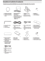
Check Accessory PartsNerifiez les accessoires/Compruebe los accesorios
0
CD
CD
CD
Rearview camera {O.Sm)
Camera de recul {O,Sm)
Camara de marcha atras
(O,Sm)
x2
®
®
®
®
®
®
Hexagonal wrench
Cle6pans
Llave hexagonal
®
®
®
Power unit (Reverse/
ACC/GND: 1m)
Alimentation
{Reverse/ACC/GND: 1m)
Unidad de alimentacion
{Marcha atras/ACC/
TIERRA: 1m)
RCA extension cable
{Sm)
Rallonge RCA {Sm)
Cable de extension RCA
{5 m)
@ Camera mounting
bracket
@ Support de fixation
@ Soporte de Ia camara
(J) ACC connection cable
(6m)
(J) Cable Accessorie {6m)
(J) Cable de conexion ACC
(6m)
@ Hexscrew
@ Vis hexagonale
@ Tornillo hexagonal
@ Waterproofing pad
@ Protege cable etanche
@ Dispositivo protector
resistente al agua
I
x4
xS
®
®
®
Waterproofing pad
adhesive sheet
Adhesif pour protege
cable etanche
Hoja adhesiva para el
dispositivo protector
resistente al agua
@Camera extension cable
(Sm)
@ Rallonge cable camera
{Sm)
@ Cable de extension de Ia
camera {Sm)
@ Wireclamp
@ Attache fils
@ Fijador de cables
(j]) Velcro fastener
(j]) Bande velcro
(j]) Fijador de velcro
@ Self-tapping screw
@ Vis autotaraudeuse
@ Tornillo macho roscador
Installation Location/Emplacement de l'installation/Ubicaci6n de Ia instalaci6n
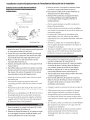
Install the Camera on the Rear Bumperflnstallez Ia
camera sur Ia carrosserje arrji:reflnstalad6n en el
acabado trasero
3 Faites un trou de 13 mm dans Ia carrosserie arriere
pour fixer le support de fixation (schema 3).
4 Faites passer le cable de Ia camera a l'interieur du
vehicule par le trou fait al'etape 3.
5 Retirez le film protecteur du support de fixation,
puis fixez ce dernier sur le chassis du vehicule.
Le cas echeant, fixez le support a l'aide des vis
autotaraudeuses.
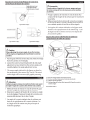
Fig.l/Schema 1/Fig.l
Fig.2/Schema 2/Fig.2
Fig.3/Schema 3/Fig.3
English
2
3
4
5
Attach the camera G) to the camera mounting bracket
@ using the hex screws@ (see Fig.2).
Loosen the camera mounting bracket@ and angle
adjustment screw. Determine the attachment angle,
and carefully tighten the angle adjustment screw.
Make a 13 mm hole in the rear bumper camera
mounting bracket (see Fig. 3).
Pull the camera cable inside the car through the hole
made in step 3.
Peel off the adhesive seal from the camera mounting
bracket and attach the camera mounting bracket on
the chassis of the vehicle. If required, fix the camera
mounting bracket using self-tapping screws.
• Attach the camera in a position where it does not touch
the number plate.
• Use retail touch-up paint to paint the surface and
surrounding area when a hole has been made in a metal
surface.
• Waterproof securely the hole made for the camera cable
using a commercially-available waterproof tape or sealing
material.
• If necessary, use a self-tapping screw@ to fix the camera
mounting bracket (In the case of a plastic mount area).
• You can also install the camera by using the sub bracket
supplied with KTX-ClOLP (License Plate Mounting Kit
for Rearview Camera) (sold separately).
Fran~ais
Fixez Ia camera G) au support de fixation@ aI'aide
des vis hexagonales@ (schema 2).
2 Deserrez le support de fixation@ et inserez en angle
Ia vis de reglage. Choisissez l'angle de fixation, puis
reserrez delicatement Ia vis dans cet angle.
• Fixez la camera de faron ace qu'elle ne touche pas la
plaque d'immatriculation.
• Si vous avez perce un trou dans une surface metallique,
une retouche est necessaire sur et autour de la surface avec
une peinture speciale.
• Les passes-fils a l'interieur du vehicule doivent etre
impermeables ; pour cela, utilisez du ruban adhesif
impermeable ou un autre produit d'etancheite vendu dans
le commerce.
• Si besoin est, utilisez une vis autotaraudeuse @ pour
fixer le support de fixation (notamment si la surface de
montage est en plastique).
• Vous pouvez installer la camera a l'aide du sous-support
fourni avec le KTX-ClOLP (License Plate Mounting Kit
for Rearview Camera) (vendu separement).
Espaiiol
2
3
4
5
Fije Ia camara G) al so porte de Ia camara@ con los
tornillos hexagonales@ (vease Ia figura 2).
Afloje el soporte de Ia camara@ e inserte en angulo
el tornillo de ajuste. Calcule el angulo de fijaci6n y,
con cuidado, apriete el tornillo en dicho angulo.
Realice un agujero de 13 mm en el soporte de Ia
camara del acabado trasero (vease Ia figura 3).
Tire del cable de Ia camara desde el interior del cache
a traves el agujero del paso 3.
Retire el sella adhesivo del soporte de Ia camara y
fljelo en el chasis del vehfculo. Si fuera necesario, fije
el soporte de Ia camera con ayuda de los tornillos
embriados suministrados.
• Coloque la camara en una posicion en la que no toque la
matricula.
• Utilice pintura para retocar la superficie y el area que
rodea el agujero realizado en la superficie de metal.
• Para garantizar que las arandelas aislantes colocadas
en el interior del vehiculo son resistentes al agua, utilice
cinta adhesiva resistente al agua o algun tipo de material
sellante.
• Si es necesario, utilice un tornillo macho roscador @ para
fijar el soporte de la camara (en caso de que el area de
instalaci6n sea de plastico ).
• Tambien puede instalar la camara utilizando el soporte
auxiliar suministrado KTX-Cl OLP (License Plate
Mounting Kit for Rearview Camera) (se vende por
separado).
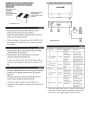
Connectjons/Raccordements/Conexjones
Installing the power Unjtflnstallatjon du bloc
d'aljmentatjonflnstaladOn de Ia unjdad de
alimentadOn
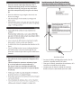
~LPINE
Bottom of power unit/
Sousde bloc
d'alimentation/
Parte inferior de unidad
de alimentacion
Velcro fastener (hard side}/
Bande velcro (cote
rugueux}/Fijador de velcro
!
V.OOT
(cara dura)
Fig.4/Schema 4/Fig.4
English
Attach the Velcro fastener (hard side)@ to the
bottom of the power unit® (see Fig. 6).
2 Attach the Velcro fastener (soft side)@ to the floor,
and secure the power unit®.
• When attaching the Velcro fastener (hard side) @ to the
floor carpet, do so without the Velcro fastener (soft side)
@attached.
Fig.S/Schema 5/Fig.S
English
Fran~ais
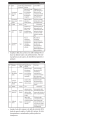
No.
Fixez Ia bande velcro (cote rugueux)@ sous le bloc
d'alimentation ® (schema 6).
2 Fixez Ia bande velcro (cote doux)@ au sol, puis
attachez le bloc d'alimentation ®.
Name
Lead color
m
[]]
Espaliol
Coloque el fijador de velcro (cara dura)@ en Ia parte
inferior de Ia unidad de alimentaci6n ® (vease Ia
figura 6).
2 Coloque el fijador de velcro (cara blanda)@ en el
suelo y fije Ia unidad de alimentaci6n ®.
• Al colocar el fijador de velcro (cara dura)@ en la
moqueta del suelo, hagalo sin despegar la cara blanda del
velcro @.
Connect to
Function
Video Output
Connector
--
• Lorsque vous fixez la bande velcro (cote rugueux)@ au
sol, fixez-la sans decoller le cote doux de la bande velcro
@.
Specification/
rn
[!]
~
Rear Camera
Connector
Fuse
Reverse/ ACC
Lead
Ground Lead
--Orange/
white
Black
Outputs a
Connect the RCA
camera video on
extension cable
the connected
(included), and then
monitor or
to the camera video
navigation
input connector of the
system .
connected device.
Inputs the rear
Connect the camera
camera video
extension cable to the
signal.
rear camera.
?.SA
When reversing
Connect the lead to
the vehicle, the
the positive side of
lead is used to
the rear lamp feed of
supply power to
the vehicle, or the ACC
the unit.
position.
Fix the lead
Connect the lead
securely to a
securely to a metal
metal part of the
part of the car's
car's chassis.
chassis. Failure to
do so may cause a
malfunction.
• Install the camera cable and RCA extension cable wiring
away from the radio antenna and antenna cable. If they
are too close, or wrapped together, noise can result.
Fran~ais
No
Nom
Connecteur
[I]
de sortie
video
Couleur du
Caracteristique/
connecter
fonction
---
Le raccorder
a
Reproduit l'image
Raggordez-le au
de Ia camera
cable rallonge RCA
sur le moniteur
(fourni), puis au
connecte ou
connecteur d'entree
le systeme de
video de Ia camera
navigation.
du peripherique
Diffuse le signal
Connectez le cable
connecte.
Connecteur
[I]
de Ia camera
arriere
w
[I]
Fusible
Fil Reverse/
ACC
----Orange/
blanc
video de Ia
rallonge de Ia camera
camera arriere.
a Ia camera arriere.
7,5A
a Ia
Lorsque vous
Connectez ce fil
faites marche
borne positive de
arriere, ce fil
!'alimentation du feu
est utilise pour
arriere du vehicule,
alimenter l'unite.
ou placez Ia cle de
contact en position
ACC.
~
Conducteur
de terre
Noir
Fixez ce
Raccordez ce
connecteur
connecteur
a un
correctement
correctement
a un element
element metallique
metallique
du chassis du
du chassis du
vehicule. Dans le
vehicule.
cas contraire, un
dysfonctiopnnement
peut se produire.
• Installez le cable de la camera et le cable rallonge RCA a
lecart de l'antenne radio et du cable d'antenne. S'ils sont
trap prets les uns des autres, des interferences peuvent se
produire.
Espanol
N.o
Nombre
Color del
cable
Con ector
[I]
de salida de
---
video
Especificacion/
Conectar a
Funcion
Emite Ia imagen
Conecte el cable
de Ia camera
de extension RCA
en el monitor
(incluido) y, a
o en el sistema
continuacion, el
de navegacion
conector de entrada
conectado.
de Ia camera del
recibe Ia serial
Conecte el cable
de video de Ia
de extension de Ia
camera trasera.
camera a Ia camera
dispositive conectado.
Con ector
[I]
de camera
---
trasera
w
Fusible
trasera.
---
7,5A
Cuando el
[I]
Cable Marcha
atras/ACC
Naranja/
Blanco
Conecte el cable al
vehiculo circula
borne positivo de Ia
marcha atras, este
alimentacion de faros
cable se utiliza
traseros del vehiculo, o
para alimentar Ia
bien a Ia posicion ACC.
unidad.
~
Cable de
tierra
Negro
Fije el cable
Conecte el cable
correctamente a
correctamente a una
una pieza metalica
pieza metalica del
del chasis del
chasis del vehiculo. Si
vehfculo.
nolo hace, Ia unidad
pod ria no funccionar
correctamente.
• Instale el cable de la camara y el cable de extension RCA
desde la antena de radio y el cable de la antena. Si estan
demasiado cerca o entrelazados, podian producirse
interferencias.
Adjysting the Camera Angle/Reglage de l'angle de Ia
camera/Ajyste del iingylo de Ia qimara
Espaliol
Angle adjustment screw/
Vis de reglage d'angle/
Tornillo de ajuste en angulo
& Precauci6n
Cuando ajuste el iingulo de Ia ciimara, apague primero
el motor y ponga el freno de mano para evitar posibles
accidentes.
Ponga Ia palanca de marchas en marcha atras (R) y
compruebe Ia imagen de Ia camara que se muestra en
Ia pantalla.
2 Afloje el soporte de Ia camara ® e inserte en angulo
el tornillo de ajuste. Calcule el angulo de Ia Camara y,
con cuidado, apriete el tornillo en dicho angulo.
Fig.6/Schema 6/Fig.6
*
Los angulos de la camara indicados en las figuras estan
basados en las especificaciones de la camara (Fig. 7 y 8).
El angulo real de la camara sera mas corto despues del
procesamiento grafico.
Secyring the Camera Cable/Fixation dy cable de Ia
camera/Fjjaci6n del cable de Ia ciimara
Fig. 7/Schema 7/Fig. 7
Fig.8/Schema 8/Fig.S
English
&caution
When adjusting the camera angle, do so after turning
off the engine and applying the hand brake to avoid an
accident.
Put the gear shift into reverse (R), and check the image
from the camera on the display.
2 Loosen the camera mounting bracket@ and angle
adjustment screw. Determine the camera angle, and
carefully tighten the angle adjustment screw.
*
The camera angles indicated in the figures are based on
the specification of the camera (Fig.7 and 8). The actual
camera angle will be narrower after graphic processing.
Fran~ais
&Attention
Veillez a couper le moteur eta mettre le frein a main avant
de regler I'angle de Ia camera afin d'eviter tout accident.
Mettez le levier de vitesse en marche arriere (R), puis
verifiez l'image de Ia camera affichee l'ecran.
2 Deserrez le support de fixation@ et inserez en angle
Ia vis de reglage. Choisissez l'angle de Ia camera, puis
reserrez delicatement Ia vis dans l'angle.
a
* Les angles de la camera indiques dans les schemas sont
bases sur les specifications de la camera (schemas 7 et
8). I.:angle reel de la camera sera plus precis apres le
traitement graphique.
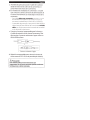
(A) Rearview camera/Camera arriere/Camera trasera
(B) To Power unit/Bloc d'alimentation/Unidad de alimentacion
(C) Clamper/Attache-fils/Fijador
(D) Waterproofing pad/Protege-cables impermeable/Dispositivo protector
resistente al agua
Fig. 9/Schema 9/Fig. 9
English
Secure the camera cable while referring to Fig. 9.
Attach the waterproof pad® with the waterproof
pad adhesive sheet@, and secure any slack cable
around the waterproof pad® using the wire clamp
Speciallnstructjons for pickup Truck Installations/
lnstryctions sp@ciales poyr jnstallatjon syr yo pjckyp/
lnstrycciones especiales para las jnstalaciones en camionetas
t
Front of pickup truck*/
@.
Avant du pickup*/
Parte delantera de Ia camioneta*
• Ensure the cable does not get caught in the trunk, rear
door(s) or any hinges.
• The cable should go on the outside of car hinges and
harness covers.
• After completing wiring, open and close the trunk and the
rear doors several times to confirm the cable is not getting
caught or rubbing anywhere.
Recommended camera power supply mounting
location (inside pickup cab)/
Emplacement de montage recommande de
!'alimentation de Ia camera (a l'interieur de Ia
Fran~ais
Fixez le cable de Ia camera en vous reportant au
schema 9.
Fixez le protege-cables® sur son ruban adhesif @,
puis fixez et tendez le cable sortant du protege-cables
®a l'aide de !'attache-fils@.
• Assurez-vous que le cable n'est pas coince dans la malle,
dans les portes arrieres ou dans une charniere.
• Le cable doit etre hors des protections des charnieres et des
harnais.
• Une fois le cablage termine, ouvrez et refermez plusieurs
fois la malle arriere et les portes arrieres afin de vous
assurez que le cable n'est pas coince et qu'il ne subit aucun
frottement.
Espanol
·Fije el cable de Ia camara siguiendo el diagrama de Ia
figura 9.
Coloque el dispositive protector resistente al agua
® con Ia hoja adhesiva correspondiente ® y
fije cualquier cable que sobresalga alrededor del
dispositive resistente al agua ® con ayuda del fijador
de cables@.
• Verifique que el cable no queda atrapado en el maletero,
las puertas traseras o en cualquier bisagra.
• El cable debe estar fuera de las protecciones de las bisagras
y arneses del vehiculo.
• Una vez finalizado el cableado, abra y cierre el maletero
y las puertas traseras varias veces para compro bar que el
cable no queda atrapado ni plegado en ningun sitio.
cabine du pickup)/
Ubicacion recomendada para colocar Ia fuente
de alimentacion de Ia camara (en el interior de
Ia camioneta)
a
b
d
Fig.IO/Schema 10/Fig.IO
* Any type of vehicle, including pickup trucks, where the
connector is installed outside of the cabin.!
* Tout type de vehicule, notamment des camionnettes, ou le
connecteur est installe hors de la cabine.!
* Cualquier tipo de vehiculo, incluidas las camionetas,
donde el conector se debe instalar fuera de la cabina.
Fran~ais
English
a: Rubber grommet to pass camera wire from inside of
pickup truck cab to underside of pickup truck chassis.
b: In pickup truck* installations, the wire that connects
between the camera and the camera power supply
typically gets installed under the pickup truck chassis.
- This wire must be protected from damage using
split-loom tubing in any areas where it is installed
under the pickup chassis.
- The rubber grommet where the wire passes from the
cab to the underside of the truck must be sealed
with silicone to prevent moisture intrusion into the
pickup truck cab.l
c: Connect the water-proof connector for the camera
and camera extension cable securely. When
disconnecting the water-proof connector, use a flatblade screwdriver.
,----------,
===lQ-§r~
'-------,--J
L__
_r----
1'
I'
----------.1 ,_ ------------------------I
I
!~~!
I~
I
I
I
1---------------------------------- --1
* Water-proof connector
a: Passe-cloison en caoutchouc pour fa ire transiter le fil
de Ia camera de l'interieur de Ia cabine du pickup vers
le dessous du chassis.
·
b: En cas d'installation sur un pickup*, le fil qui relie Ia
camera ason alimentation est generalement installe
sous le chassis du vehicule.
- Le fil doit etre protege contre les degats au moyen
d'un tubage pour cablage, Ia ou il est installe sous le
chassis du pickup.
- Le passe -cloison en caoutchouc, utilise pour
acheminer le fil de Ia cabine vers le dessous du
pickup, doit etre protege avec du silicone pour
eviter toute intrusion d'humidite dans Ia cabine du
vehicule.
c: Raccordez correctement le connecteur etanche
pour camera et le cable d'extension pour camera.
Utilisez un tournevis alame plate pour deconnecter le
connecteur etanche.
,----------,
===:Q-@r~
'-------,--J
&caution
This symbol means important instructions. Failure to
heed them can result in injury or material property
damages.
_r----
I'
----------.I ,_--- ---------------------I
1
!~~!
I~
I
d: Recommended HCE-C155 rearview camera mounting
location (on rear bumper).
L__
1'
I
I
1---------------------------------- --1
* Connecteur etanche
d: Emplacement de montage recommande de Ia camera
de recul HCE-C155 (sur le parechocs arriere).
&Attention
Ce symbole designe des instructions importantes. Le nonrespect de ces instructions peut entrainer des blessures
ou des dommages materiels.
Espanol
a: Arandela de goma para pasar el cable de Ia camara
desde el interior de Ia cabina de Ia camioneta a Ia
parte inferior del chasis de Ia camioneta.
b: En instalaciones realizadas en camionetas*, el cable
que conecta Ia camara y Ia fuente de alimentaci6n de
Ia camara normal mente se instala bajo el chasis de Ia
camioneta.
- Este cable debe estar protegido mediante un tubo
de hendidura en espiral en las zonas en las que se
encuentre instalado bajo el chasis de Ia camioneta.
- La arandela de goma por el que pasa el cable desde Ia
cabina hasta Ia parte inferior de Ia camioneta se debe
sellar con silicona para evitar Ia entrada de humedad
en Ia cabina de Ia camioneta.
c: Conecte el conector impermeable para Ia camara y
el cable de extension de Ia camara firmemente. Para
desconectar el conector resistente al agua, uti lice un
destornillador plano.
r----------~
===I=CJ-§r~
j L__
1_ _ _ _ _ _ _ -;- _ _
_J-----
1'
1\
--- -------J '----- --------------------I
1
I
I
I
I
l~~l
1--------------------------------- ---'
* Conector resistente al agua
d: Ubicaci6n recomendada para colocar Ia camara de
vision trasera HCE-C155 (en el parachoques trasero).
~ Precaucion
Este simbolo indica que las instrucciones son
importantes. De no tenerse encuenta, pod ria ocasionarse
heridas graves o dalios materiales.
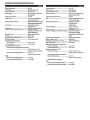
SpecifjcatjonsLSp@cifjcatjoos/Especificacjones
Fran~ais
English
Power Requirements ............................................ 14.4V DC
Puissance requise ................................................. 14,4 V DC
Ground Type .......................................................... Negative ground type
Type de masse ....................................................... Masse neg.ative
Power Consumption ............................................. less than 2.5W
Consommation d'energie ..................................... moins de 2,5 W
Output Image ........................................................ Mirror image, VBS (NTSC Color
Image reproduite .................................................. Image miroir, VBS (systeme de
signaux couleur NTSC)
signal system)
Output Drive Capacity.......................................... 75 ohms
Capacite d'excitation de sortie ............................ 75 ohms
Image Sensor ........................................................ 1/4 type color CMOS image
CCD ........................................................................ Capteur d'image CMOS couleur
1/4'~ format d'image 4 : 3
sensor, aspect ratio 4 : 3
Effective Number of Pixels ................................... 640 (horizontal) x 480 (vertical)
Nombre effectif de pixels ..................................... 640 (horizontal) x 480
approximately 300,000 pixels
(vertical), environ
Lens Section .......................................................... Focal length: f=0.82mm,
brightness: F=2.6
300.000 pixels
Section de l'objectif .............................................. Focale: f = 0,82 mm,
Angle of field ......................................................... Horizontal: 190·, Vertical: 1so·
Automatic Image Adjusting Function ................. Automatic exposure
adjustment, Automatic white
luminosite: F = 2,6
Angle de champ .................................................... Horizontal: 190°, Vertical :150°
Fonction de reglage automatique de l'image .... Controle automatique
balance adjustment
de !'exposition, reglage
Synchro-System .................................................... Internal synchronization
automatique de Ia balance des
S/N ratio ................................................................. 40dB or more
Resolution (horizontal,center area) .................... 300 TV lines
blancs
Systeme de synchronisation ................................ Synchronisation interne
Illumination Range ............................................... 1.5 lx or more (50 IRE)
Rapport signal sur bruit ...................................... 40dB et plus
Operating Temperature Range
Resolution (horizontale,zone centrale) .............. 300 lines de Television
• Camera section ............................................... -3o·c to +7o·c
Plage d'illumination ............................................. 1,51x et plus
• Power section .................................................. -3o·c to +6o·c
Plage de temperatures de fonctionnement
External Dimensions (W x H x D)
• Section de Ia camera ...................................... -30
• Camera section (except projection on the rear)
.......................................................................... 15/16"x 15/16"x 1-1/16"
(23.4mm x 23.4mm x 25.9mm)
Dimensions externes (I x H x P)
• Section de Ia camera ...................................... 15/16" X 15/16" X 1-1/16"
• Power section (except projection) ................ 4"x 2"x 1"
(1 OOmm x SOmm x 25mm)
Weight
(23,4mm x 23,4mm x 25,9mm)
(partie saillante arriere non comprise)
• Section d'alimentation ................................... 4" x 2" x 1"
• Camera section (including cable) .................. 1 oz. (32g)
• Power section (including cable) .................... 6 oz. (182g)
a+70 oc
• Section d'alimentation ................................... -30 a+60 oc
(100mm x SOmm x 25mm)
(partie saillante non comprise)
Po ids
• Section de Ia camera (cable compris) ........... 1 oz. (32g)
• Section d'alimentation (cable compris) ........ 6 oz. (182g)
Espafiol
Requisitos de alimentacion ................................. 14,4 V CC
Tipo de tom a de tierra .......................................... Tipo toma de tierra negativa
Consumo de energia ............................................ menos de 2,5 W
Imagen de salida ................................................... Imagen en espejo, VBS (sistema
de seflal a color NTSC)
Capacidad de impulso de salida ......................... 75 ohmios
Sensor de imagen ................................................. Sensor de imagen CMOS de 1/4
pulg., relacion de aspecto 4 : 3
Numero efectivo de pixeles ................................ 640 (horizontal) x 480
(vertical), aproximadamente
300.000 pixeles
Seccion de Ia lente ................................................ Longitud focal: f = 0,82 mm,
brillo: F =2,6
Angulo de campo .................................................. Horizontal: 190°, Vertical: 150°
Funcion de ajuste de imagen automatico .......... Ajuste automatico de
exposicion; Ajuste automatico
de balance de blancos
Sistema de sincronizacion ................................... Sincronizacion interna
Relacion seflal-ruido ............................................ 40dB o mas
Resolucion (horizontal, area central) .................. 300 lineas de televisor
Alcance de Ia iluminacion .................................... de 1,5 a 100.000 lx
Intervale de temperatura de funcionamiento
• Seccion de camara .......................................... -Entre 30 y + 70°(
• Seccion de alimentacion ................................ -Entre 30 y +60°(
Dimensiones externas (ancho x alto x largo)
• Seccion de camara .......................................... 15/16" x 15/16" x 1-1/16"
(23,4mm x 23,4mm x 25,9mm)
(excepto proyeccion trasera)
• Seccion de alimentacion ................................ 4" x 2" x 1"
(100mm x 50mm x 25mm)
(excepto proyeccion)
Peso
• Seccion de camara (incluido cable) ............... 1 oz. (32g)
• Seccion de alimentacion (incluido cable) ..... 6 oz. (182g)
Thank you for choosing Alpine for your car audio equipment needs. Our goal is to
produce the best audio/video/navigation products in the world and hope your
expectations are met.
Please take a moment to protect your purchase by registering your product now at
the following address: www.alpine-usa.com/registration. You will be informed of
product and software updates (if applicable), special promotions, and news about
Alpine. Also, by registering your product, you will automatically be entered for a
chance to win various prizes such as gift cards, Alpine products, and/or a complete
system.
We look forward to continue serving you in the future.
Sincerely,
The Alpine Team
Spanish
French
Nous vous remercions d'avoir porte votre choix sur un
equipement audio automobile Alpine. Notre principal
objectif est de fabriquer les meilleurs produits audio,
video et de navigation au monde afin de repondre aux
exigences de nos clients.
Gracias por elegir Alpine para las necesidades de
equipamiento de audio de su vehfculo. Nuestro
objetivo es fabricar los mejores productos de audio/
vfdeo/navegaci6n del mundo y esperamos poder
cumplir sus expectativas.
Veuillez prendre quelques instants pour securiser
votre achat en enregistrant votre produit l'adresse
suivante : www.alpine-usa.com/registration. Vous
serez tenu informe des nouveaux produits, des mises
a jour logicielles (le cas echeant), des promotions
speciales et des informations concernant Alpine.
L'enregistrement de votre produit vous donne par
ailleurs Ia possibilite de gagner des dizaines de
cadeaux, tels que cheques-cadeaux et articles Alpine,
ainsi qu'un systeme complet.
Dedique unos momentos a proteger su compra:
registre ahara su producto en Ia siguiente direcci6n:
www.alpine-usa.com/registration. Recibira
informacion de novedades sabre el producto y
actualizaciones de software (si se producen),
promociones especiales y noticias de ultima hora de
Alpine. Asimismo, si registra su producto, entrara
automaticamente en el sorteo de diversos premios,
como tarjetas de regalo, productos de Alpine y/o un
sistema completo.
Nous esperons que nos produits vous donneront
entierement satisfaction.
Esperamos poder seguir ofreciendole el mejor
servicio en el futuro.
Cordialement,
Atentamente,
L'equipe Alpine
El equipo de Alpine
a
PART NO. 68-2 16272 36-A
M35441 5301 0
~LPINE®
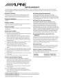
LIMITED WARRANTY
ALPINE ELECTRONICS OF AMERICA, INC. AND ALPINE OF CANADA INC. ("Alpine"), are dedicated to quality craftsmanship and are pleased to offer this
Warranty. We suggest that you read it thoroughly. Should you have any questions, please contact your Dealer or contact Alpine at one of the telephone
numbers listed below.
e PRODUCTS COVERED:
e HOW WE LIMIT IMPLIED WARRANTIES:
This Warranty covers Car Audio Products and Related Accessories ("the
ANY IMPLIED WARRANTIES INCLUDING FITNESS FOR USE AND
product"). Products purchased in the Canada are covered only in the
MERCHANTABILITY ARE LIMITED IN DURATION TO THE PERIOD OF THE
Canada. Products purchased in the U.S.A. are covered only in the U.S.A.
e LENGTH OF WARRANTY:
This Warranty is in effect for one year from the date of the first consumer
purchase.
e WHO IS COVERED:
This Warranty only covers the original purchaser of the product, who must
EXPRESS WARRANTY SET FORTH ABOVE AND NO PERSON IS AUTHORIZED
TO ASSUME FOR ALPINE ANY OTHER LIABILITY IN CONNECTION WITH THE
SALE OF THE PRODUCT.
e HOW WE EXCLUDE CERTAIN DAMAGES:
ALPINE EXPRESSLY DISCLAIMS LIABILITY FOR INCIDENTAL AND
CONSEQUENTIAL DAMAGES CAUSED BY THE PRODUCT. THE TERM
reside in the United States, Puerto Rico or Canada.
"INCIDENTAL DAMAGES" REFERS TO EXPENSES OF TRANSPORTING THE
PRODUCTTOTHE ALPINE SERVICE CENTER, LOSS OF THE ORIGINAL
e WHAT IS COVERED:
PURCHASER'S TIME, LOSS OF THE USE OF THE PRODUCT, BUS FARES, CAR
RENTALS OR OTHERS COSTS RELATING TO THE CARE AND CUSTODY OF THE
This Warranty covers defects in materials or workmanship (parts and labor)
in the product.
e WHAT IS NOT COVERED:
This Warranty does not cover the following:
Damage occurring during shipment of the product to Alpine for repair
CD
(claims must be presented to the carrier).
®
Damage caused by accident or abuse, including burned voice coils
caused by over-driving the speaker (amplifier level is turned up and
driven into distortion or clipping). Speaker mechanical failure (e.g.
punctures, tears or rips). Cracked or damaged LCD panels. Dropped or
damaged hard drives.
@ Damage caused by negligence, misuse, improper operation or failure
to follow instructions contained in the Owner's manual.
@ Damage caused by act of God, including without limitation,
®
®
REPAIRING OR REPLACING OTHER PROPERTY WHICH IS DAMAGED WHEN
THIS PRODUCT DOES NOT WORK PROPERLY. THE REMEDIES PROVIDED
UNDER THIS WARRANTY ARE EXCLUSIVE AND IN LIEU OF ALL OTHERS.
e HOW STATE/PROVINCIAL LAW RELATES TO THE
WARRANTY:
This Warranty gives you specific legal rights, and you may also have other
rights which vary from state to state and province to province. In addition,
some states/provinces do not allow limitations on how long an implied
warranty lasts, and some do not allow the exclusion or limitation of
incidental or consequential damages. Accordingly, limitations as to these
matters contained herein may not apply to you.
e IN CANADA ONLY:
earthquake, fire, flood, storms or other acts of nature.
Any cost or expense related to the removal or reinstallation of the
This Warranty is not valid unless your Alpine car audio product has been
product.
Service performed by an unauthorized person, company or association.
warranty stamped upon installation by the installation center.
Any product which has the serial number defaced, altered or removed.
e HOW TO CONTACT CUSTOMER SERVICE:
(j) Any product which has been adjusted, altered or modified without
@
Alpine's consent.
Any product not distributed by Alpine within the United States, Puerto
®
Rico or Canada.
Any product not purchased from an Authorized Alpine Dealer.
e HOW TO OBTAIN WARRANTY SERVICE:
CD
PRODUCT. THE TERM "CONSEQUENTIAL DAMAGES" REFERS TO THE COST OF
installed in your vehicle by an Authorized Installation Center, and this
Should the product require service, please call the following number for
your nearest Authorized Alpine Service Center.
CAR AUDIO
1-800-ALPINE-1 (1-800-257-4631)
NAVIGATION
1-888-NAV-HELP (1-888-628-4357)
Or visit our website at; http://www.alpine-usa.com
You are responsible for delivery of the product to an Authorized
Alpine Service Center or Alpine for repair and for payment of any initial
shipping charges. Alpine will, at its option, repair or replace the product
with a new or reconditioned product without charge. If the repairs
are covered by the warranty, and if the product was shipped to an
Authorized Alpine Service Center or Alpine, Alpine will pay the return
®
shipping charges.
You should provide a detailed description of the problem(s) for which
service is required.
@ You must supply proof of your purchase of the product.
@ You must package the product securely to avoid damage during
shipment. To prevent lost packages it is recommended to use a carrier
that provides a tracking service.
ALPINE ELECTRONICS OF AMERICA, INC., 19145 Gramercy Place, Torrance, California 90501, U.S.A.
ALPINE ELECTRONICS OF CANADA, INC., 777 Supertest Road, Toronto, Ontario M3J 2M9, Canada
Do not send products to these addresses.
Call the toll free telephone number or visit the website to locate a service center.