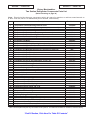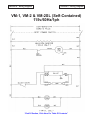
1
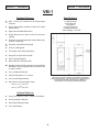
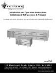
MERCHANDISER MODELS
VM-1, VM-2 & VM-2SL
INSTALLATION, OPERATION & SERVICE
MANUAL
(For “Quick Navigation”, Click On Topics or Sections Highlighted In Blue)
★
DESCRIPTION
★
INSTALLATION
★
OPERATION
★
MAINTENANCE
★
SERVICE
★
TROUBLESHOOTING
★
PARTS LISTS
★
WIRING DIAGRAMS
LIMITED WARRANTY
(Continental USA Only)
The Seller warrants to the original purchaser, equipment manufactured by Seller to be free from defects in
material and workmanship for which it is responsible. The Seller’s obligation under this warranty shall be
limited to replacing or repairing at Seller’s option, without charge, F.O.B. Sellers factory, any part found to be
defective and any labor and material expense incurred by Seller in repairing or replacing such part, such
warranty to be limited to a period of 90 days from date of purchase or 120 days from date of shipment from
Seller’s factory, whichever is earlier, provided terms of payment have been fully met. All labor shall be
performed during regular working hours. Overtime premium charges will be at Buyer’s expense.
In addition to the above, Seller will replace any part deemed by it to be defective without charge for such
replacement except labor charges, such warranty to be limited to period of one year from date of purchase or
13 months from date of shipment of the equipment from Seller’s factory.
Proof of purchase must be supplied to Seller to validate warranty. This warranty is valid only if equipment is
properly installed, started-up and checked out by the dealer or Victory authorized Service agent.
Removal or alteration of the serial/data plate from any equipment shall be deemed to release Seller from all
warranty obligations or any other obligations, expressed or implied.
This warranty does not cover Thermostat or Defrost Timer calibration and/or adjustment, freight damage,
normal maintenance items outlined in Owner’s Manual, adjustment of door mechanisms or replacement of
light bulbs, fuses or batteries.
Any repairs or replacement of defective parts shall be performed by Seller’s authorized service personnel.
Seller shall not be responsible for any costs incurred if the work is performed by other than Seller’s authorized
service personnel. Reimbursement claims for part(s) or labor service costs must be made in writing. Model,
cabinet serial numbers and installation location must be shown on the claim. A receipt from the servicing
agency must accompany the claim, together with full details of the service problems, diagnosis and work
performed. Victory reserves sole discretion whether further documentation on a claim is to be submitted.
Seller shall not be liable for consequential damages of any kind which occur during the course of installation
of equipment, or which result from the use or misuse by Buyer, its employees or others of the equipment
supplied hereunder, and Buyer’s sole and exclusive remedy against Seller for any breach of the foregoing
warranty or otherwise shall be for the repair or replacement of the equipment or parts thereof affected by such
breach.
The foregoing warranty shall be valid and binding upon Seller if and only if Buyer loads, operates and
maintains the equipment supplied hereunder in accordance with the instruction manual provided to Buyer.
Seller does not guarantee the process of manufacture by Buyer or the quality of product to be produced by
the equipment supplied hereunder and Seller shall not be liable for any prospective or lost product or profits
of Buyer.
THE FOREGOING WARRANTY IS EXCLUSIVE AND IN LIEU OF ALL OTHER EXPRESS AND IMPLIED
WARRANTIES WHATSOEVER. SPECIFICALLY THERE ARE NO IMPLIED WARRANTIES OF
MERCHANTABILITY OR OF FITNESS FOR A PARTICULAR PURPOSE.
The foregoing shall be Seller’s sole and exclusive obligation and Buyer’s sole and exclusive remedy for any
action, whether in breach of contract or negligence. In no event shall seller be liable for a sum in excess of
the purchase price of the item.
110 Woodcrest Road · Cherry Hill, NJ 08003-0507 · Phone (856) 428-4200 · Fax (856) 428-7299
Victory Service Line is (800) 523-5008
i
-OPTIONALADDITIONAL FOUR YEAR
MOTOR COMPRESSOR WARRANTY
ADDITIONAL PROTECTION PLAN FOR MOTOR COMPRESSOR
ONLY
Victory agrees to reimburse the original purchaser, after the initial twenty (20) month
warranty supplied by compressor manufacturer expires, for five (5) years after the date of
shipment for the net exchange cost of the replacement motor-compressor less any labor,
freight, taxes and handling charges.
The term “original purchaser-user” as used herein shall be deemed to mean that person,
firm, association, or corporation for whom the equipment was originally installed.
The term “motor-compressor” as used herein does not include unit base, air or water
cooled condenser, receiver, electrical accessories such as relay, capacitors, pressure
control, or condenser fan motor assembly, etc. This warranty further does not include any
equipment to which said motor-compressor is connected, such as cooling coils,
temperature controls, refrigerant metering devices, refrigerant, etc. This warranty shall be
void if said motor-compressor in our judgment has been subjected to misuse, negligence,
accident or operated contrary to the recommendations specified by the manufacturer or if
the serial number has been altered, defaced or removed.
GENERAL CONDITIONS
Performance under this warranty is contingent upon causes beyond our control and we
shall not be liable for any default or delay in performance thereunder caused by any
contingency beyond our control including war, governmental restrictions or restraints,
strikes, fire, floods, short or reduced supply or raw material or discontinuance of the parts
or motor compressor assembly by our suppliers.
This warranty applies only to the motor-compressor installed within the continental limits of
the United States.
Replacement or repair to the defective motor-compressor is limited to a $500.00 maximum
expenditure during the four year period.
This warranty does not give the owner of the refrigerator or freezer the rights to purchase a
complete replacement condensing unit of the same make or another make. It further does
not permit the replacement to be made with a motor-compressor of another make unless
written approval is authorized.
Expressly excluded from this warranty are damages resulting from spoilage of goods or any
other incidental damages inasmuch as this warranty applies only to the replacement of
defective motor-compressor.
Failure of the customer to return their registration card containing the name, address, date
of installation, model and serial number of the refrigerator or freezer, within 10 days from
date of start-up shall void this warranty.
ii
PROCEDURE FOR OBTAINING REPLACEMENT
COMPRESSORS IN WARRANTY
Changes in engineering standards cause variations in compressor
specifications. These changes are brought about by our upgrading programs
and our suppliers engineering product changes. It is impractical for the
customer to go to the manufacturer for the replacement compressor. Suppliers
have set up wholesaler organizations to handle replacements on a local basis.
The standard O.E.M. (original equipment manufacturers) warranties are for an
unconditional 20 months from date of manufacture at their factory. This allows
several months for Victory to install a compressor and get the cabinet into the
field.
A defective compressor must be taken to a local wholesaler and exchanged for
a new one. If the first three digits of the defective compressor serial number
shows that it is less than 20 months old, the wholesaler is obligated to give an
even exchange.
The additional four year warranty is available from Victory Refrigeration, 110
Woodcrest Road, Cherry Hill, NJ 08003.
If the defective compressor is past 20 months of age, it must be exchanged
with the local wholesaler and the service company, dealer, or the customer
must temporarily pay for a new compressor, *less any salvage value of the
original. A copy of the original wholesale invoice and salvage credit memo,
must then be sent to Victory, with the model and serial number of our cabinet.
Victory will reimburse them for the net exchange price, less any labor, freight,
tax, or handling charges. Reimbursements are not prorated over the five year
warranty.
(*Note: Salvage credit applies to Copelamatic units only)
If any difficulties arise beyond those mentioned, please call us directly at 1-800-523-5008.
iii
RETAIN THIS MANUAL FOR FUTURE REFERENCE
NOTICE
Victory (Manufacturer) reserves
the right to change
specifications at any time.
IMPORTANT
Warranty Registration Card Enclosed.
Failure to Properly Register
Equipment Can Void Warranty !!!!
NOTICE
Please Read The Entire Manual
Carefully Before Installation.
If Certain Recommended Procedures Are Not
Followed, Warranty Claims Will Be Denied !!!!
Machine Serial Number_______________________________
Installation Date_____________________________________
Victory Refrigeration Service Hotline (800) 523-5008
iv
TABLE OF CONTENTS
Pages
Section 1 - Description................................................................................................................................ 1
A. Control and Component Location........................................................................................... 2
B. Component Function................................................................................................................ 2-3
C. Standard Features, Optional Features and Specifications.................................................. 4- 5
Section 2 - Installation................................................................................................................................ 6
A.
B.
C.
D.
E.
F.
G.
H.
I.
J.
K.
L.
Receiving Shipment.................................................................................................................
Uncrating Procedure................................................................................................................
Reducing Merchandiser Depth................................................................................................
Locating Your New Merchandiser...........................................................................................
Installing Legs or Casters.......................................................................................................
Leveling......................................................................................................................................
Initial Cabinet Set-up...............................................................................................................
Electric Supply..........................................................................................................................
Installation Checklist................................................................................................................
Location of Serial Number/Data Plate....................................................................................
VM Standard Shelf Installation Instructions..........................................................................
Assembling and Installing VM-2 & VM-2SL Beverage Organizer Shelf..............................
6
6
6
6- 7
7
7
7
7- 8
8
8
9- 10
11-12
Section 3 - Operation.................................................................................................................................. 13
A. Temperature Control................................................................................................................. 13
Section 4 - Maintenance............................................................................................................................. 14
A.
B.
C.
D.
Cleaning and Proper Detergent Use......................................................................................
Initial Cleaning of Cabinet......................................................................................................
Periodic Cleaning....................................................................................................................
Lubrication...............................................................................................................................
14
14
14-16
16
Section 5 - Service..................................................................................................................................... 17
A.
B.
C.
D.
Servicing the Refrigeration Condensing Unit......................................................................
Servicing Evaporator Fan Motor(s) and Temperature Control...........................................
Servicing Evaporator Coil and/or Heat Exchanger Assembly............................................
VM-2SL Sliding Glass Door Shim Insertion Instructions....................................................
17
17-18
18-19
20-23
Section 6 - Troubleshooting.....................................................................................................................
24-26
Section 7 - Parts List................................................................................................................................. 27
A.
B.
C.
D.
One Section Cabinet and Hinged Glass Door Parts...........................................................
Two Section Cabinet and Hinged / Sliding Glass Door Parts............................................
One Section Refrigeration Components..............................................................................
Two Section Refrigeration Components..............................................................................
28-29
30-31
32-33
34-35
Section 8 - Wiring Diagram......................................................................................................................
36
A. VM-1D-QS, VM-2D-QS & VM-2SL-QS Wiring Diagram........................................................
37
v
Section 1 - Description
Section 1 - Description
SECTION 1
DESCRIPTION
Victory Merchandiser Refrigerators are Reach-In Models with full length glass swing
doors on the front. There is also an optional full length sliding glass door assembly that
is available for the two section model only.
Victory Merchandiser One Section Model
Figure 1-1
1
Section 1 - Description
A.
Section 1 - Description
Control and Component Location
4
3
5
1
2
Figure 1-2
Component Location
B.
Component Function
1. Doors - Swing doors are reversible for one (1) section only, and have
adjustable self-closing features.
a. Door Size - The doors are full length.
b. Door Type - The doors are sealed glass.
c. Door Hinges - The doors consist of pin hinges.
2
Section 1 - Description
Section 1 - Description
2. Refrigeration System - The refrigeration
system is self-contained and slides out for
easy service.
3. Shelves - (Refer to Figure 1-2 and to the
Parts List Section of this manual).
a. Wire Shelves - Heavy-duty epoxy
coated wire shelves are adjustable and
can be angled downward for gravityfeed merchandising.
4. Cabinet - The cabinet exterior is painted
galvanized steel. Doors are sealed argonfilled glass. Foamed-in-place polyurethane
insulation through the cabinet ensures the
ultimate in energy efficiency.
5. Temperature Control - Located inside top
of unit.
6. Thermometer (not shown) - The
thermometer is a standard feature.
3
Section 1 - Description
Section 1 - Description
VM-1
Standard Features:
●
NSF 7 Listed for Foodservice & Prepackaged
Products
●
Heavy Gauge Black Powder Coated Zinc Plated
Steel Exterior
●
High Impact Molded ABS Interior
●
Bright White Interior with Vertical Fluorescent
Lighting
●
Fluorescent Lamp Replaceable without Removing
Product or Shelving
●
Automatic Condensation Disposal
●
CFC Free Refrigerant
●
Full Height Self-Closing Glass Door
●
Integral Full Length Door Handle
●
Door Field Rehingeable
●
Bottom Mount Condensing Unit
●
Molded-In Shelf Support System Accommodates
Standard or Gravity Organizer Shelves without use
of Clips or Hooks
●
Four (4) Standard Shelves
●
Shelves Adjustable on 3” Centers
●
9 ft Cord and Plug Attached
●
Each Shelf will Accommodate either
- One (1) 12” x 20” Pan
or
- One (1) 18” x 26” Pan
Specifications:
1/5 Horse Power
115V/60Hz/1Ph
7.2 Amperes
21 Cubic Feet (net)
4 Standard Shelves
Crated Weight: 310 LBS
We reserve the right to change specifications and product
design without notice. Such revisions do not entitle the buyer
to correspond changes, improvements, additions or
replacements for previously purchased equipment.
Optional Features:
●
Heavy Duty Swivel 3” and 5” Casters with Brakes
●
Gravity Organizer Shelves
●
Door Merchandising Decals
●
Price Tag Molding
4
Section 1 - Description
Section 1 - Description
VM- 2 & VM- 2SL
Standard Features:
●
NSF 7 Listed for Foodservice & Prepackaged
Products
●
Heavy Gauge Black Powder Coated Zinc Plated
Steel Exterior
●
High Impact Molded ABS Interior
●
Bright White Interior with Vertical Fluorescent
Lighting
●
Automatic Condensation Disposal
●
CFC Free Refrigerant
●
Full Height Self-Closing Glass Door
●
Integral Full Length Door Handle
●
Bottom Mount Condensing Unit
●
Molded-In Shelf Support System Accommodates
Standard or Gravity Organizer Shelves without use
of Clips or Hooks
●
Eight (8) Standard Shelves
●
Shelves Adjustable on 3” Centers
●
9 ft Cord and Plug Attached
●
Each Shelf will Accommodate either
- One (1) 12” x 20” Pan
or
- One (1) 18” x 26” Pan
●
Each VM-2SL Shelf will Accommodate
- One (1) 12” x 20” Pan
Optional Features:
●
Heavy Duty Swivel 3” and 5” Casters with Brakes
●
Gravity Organizer Shelves
●
Door Merchandising Decals
●
Price Tag Molding
Specifications:
1/3 Horse Power
115V/60Hz/1Ph
8.8 Amperes
122 Cubic Feet (net)
8 Standard Shelves
Crated Weight: 520 LBS
We reserve the right to change specifications and product
design without notice. Such revisions do not entitle the buyer
to correspond changes, improvements, additions or
replacements for previously purchased equipment.
“End Of Section, Click Here For Table Of Contents”
Section 2- Installation
Section 2- Installation
SECTION 2
INSTALLATION
CAUTION:
Exercise extreme caution when removing
the wooden skid especially when the last
bolt is removed, as the skid, if not properly
blocked, will fall to the floor with extreme
force.
IMPORTANT:
It is highly recommended that your
merchandiser refrigerator be installed by
an authorized Victory Certified Installer.
C. R e d u c i n g M e r c h a n d i s e r D e p t h f o r
Narrow Facility Doorway
A. Receiving Shipment
In order to pass through a narrow doorway or
restricted area the door, front grille and hinge
brackets may be removed to reduce the overall
depth of the cabinet to a minimum or 30" deep.
Upon arrival, examine the exterior of the
shipment packaging for any signs of rough
handling.
If the cabinet is damaged, it should be noted on
the delivery slip or bill of lading and signed to
that effect. A claim must be filed immediately
against the carrier indicating extent and
estimated cost of damage incurred.
1. Removing Hinged Doors
a. Loosen the top hinge bracket screws
while holding the top bracket down.
b. While holding the door against the
cabinet, lift the top bracket until it clears
the top hinge pin.
All units are performance tested and thoroughly
inspected, prior to shipment. Upon leaving the
factory, all units are in perfect condition and the
carrier signs to this effect.
c. Lift the door until the bottom hinge pin
clears the bottom hinge bracket.
d. Remove top and bottom hinge brackets
and mount on the other side of the
cabinet. Tighten bottom hinge bracket
screws. Leave top hinge bracket screws
loose.
B. Uncrating Procedure
WARNING!!!!
DO NOT, Under Any Circumstances, Lay
Your New Equipment Down on Either The
Back, Front or Sides.
e. Insert bottom hinge pin into hole in
bottom hinge bracket.
The shipping skid must be removed by tipping
the model from side to side. Remove the
leveler bolts while the model is held in one
direction. Repeat this procedure when the
model is held in the opposite direction.
ATTENTION!!!!
f. Lower top hinge bracket onto top hinge
pin. Tighten the top hinge bracket.
D. Locating Your New Merchandiser
The following conditions should be considered
when selecting a location for your
merchandiser refrigerator.
DO NOT THROW AWAY THE FOUR (4)
LEVELER BOLTS!
*Note:Once the uncrating process is complete,
make sure the leveler bolts are safely
and securely placed back on the bottom
of the cabinet for proper support and
leveling purposes.
1. Floor Load - The floor on which the cabinet
will rest must be free of vibration and
suitably strong enough to support the
combined weights of the cabinet plus the
maximum product load which might be
6
Section 2- Installation
Section 2- Installation
doors not sealing, closing properly
condensate water not draining properly.
placed into it. To estimate the possible
product load weight it is generally conceded
that a safe figure is 35 pounds for each net
cubic foot storage space. For example, a 47
cubic foot cabinet could hold approximately
1645 pounds of product (47 x 35 = 1645).
or
G. Initial Cabinet Set-Up
Units are shipped with shelves. These items
are secured to the rear of the cabinet directly on
the wood skid.
2. Ventilation - The air cooled, self-contained
merchandiser refrigerator requires a sufficient
amount of cool, clean air. Avoid placing the
refrigerator near heat generating equipment
such as ovens, ranges, heaters, fryers,
steam kettles, etc., and out of direct
sunlight. Avoid locating the self-contained
refrigerator in an unheated room, or where
the room temperature may be below 55°F.
1. Cleaning Cabinet
CAUTION:
DO NOT Use Abrasive Cleaning Solvents.
Never scour any part of your new cabinet.
Scouring powders or chemicals may cause
damage by scratching or dulling the surface
finish. Prior to placing your new merchandiser
refrigerator and all shelves into operation, it is
advisable that the interior be washed
thoroughly with a mild detergent and water
solution.
Rinse with clear water and a
sanitizing solution. Allow cabinet to air dry.
E. Installation of Optional Legs or Casters
Merchandisers are shipped with leveler bolts
that can be used to level the cabinet. However,
legs and casters can be supplied that are of the
1/2" single stud mount type and requires no
tools for installation. Simply remove the leveler
bolts and then screw the casters or legs into the
threaded holes located on the case bottom. To
install low-profile rollers, remove carriage bolts
from caster mounting plates and insert stem
into bolt hole and tighten nut. Make sure that
torque of caster bracket is inserted into 1/2”
hole. This will prevent caster from turning.
For additional cleaning information, refer to the
maintenance section of this service manual.
2. Installing Shelves
All merchandiser models include an interior
which supports the adjustable and gravity
organizing shelving.
Tilt the cabinet in one direction approximately
eight inches and block it securely to keep it from
falling. Use several pieces of 2 x 4 lumber or
other suitable material. Screws the two left or
right legs in snug. Repeat this procedure to
install the other legs with the case bottom.
Refer to pages 9 to 12 for detailed and
illustrated shelf installation instructions for both
standard shelving and beverage shelf kits.
WARNING
H. Electric Supply
Never, Under Any Circumstances,
Lay Your New Merchandiser Refrigerator
Down On Either It’s Back, Front or Sides.
The wiring should be done by a qualified
electrician in accordance with local electrical
codes. A separate ground wire must be
supplied for all installations. A properly wired
merchandiser refrigerator will assure proper
operation. Please consult the "Data" plate
attached to the compressor to assure the
electrical requirements are correct. Supply
voltage requirements are on the cabinet serial
plate. It is recommended that a direct, properly
fused line of the proper size wire be installed
F. Leveling
Cabinet must be leveled when installed. This is
accomplished by rotating the leveler bolt.
Failure to level your cabinet may result in
7
Section 2- Installation
Section 2- Installation
from the main supply to your merchandiser. It
is most important that a voltage reading be
made at the compressor-motor electrical
connections, or as close to the compressormotor as possible, while the merchandiser is in
operation, to assure that the correct voltage
required by the compressor is being supplied.
Low or high voltage can detrimentally affect the
refrigeration unit and thereby void its warranty.
NOTE:
J. Location of Serial Number/Data Plate
The serial data plate is mounted on the upper
left interior wall.
All merchandiser refrigerator electrical systems
are internally grounded. It is recommended
that a bonding braid be secured to the base of
the refrigerator and carried to a water pipe, to
complete the ground.
NOTE:
I. Installation Checklist
After the cabinet has been installed, leveled
and cleaned as described in the preceding
paragraphs, refer to the following checklist prior
to start-up.
•
Full voltage of the correct type, on a line
not affected by the operation of other
electrical appliances, must be available
for proper operation. Condensing units
are designed to operate with a voltage
fluctuation of plus or minus 10% of the
voltage indicated on the cabinet
electrical data plate. Burn-out of a
condensing unit due to exceeding the
high or low voltage limits will void the
factory warranty.
•
Leak check all exposed refrigeration
lines. Make sure refrigeration lines are
not dented, kinked or rubbing.
•
Check condenser fan for freedom to
rotate without striking any stationary
members.
•
Cabinet must be properly leveled.
•
Do Not become alarmed if a trace of
freon gas is detected in the internal
cabinet air.
This may be due to
refrigerant used in expanding the foam
insulation used in this cabinet.
All motors are lifetime oiled and
sealed. All self-contained models are
shipped from the factory with the
service valves opened ready for
operation.
8
When ordering replacement parts,
you must include the complete
cabinet model and serial numbers.
Section 2- Installation
Section 2- Installation
K. VM Standard Shelf Installation Instructions
Step 1
Step 2
Make sure plastic end caps are on the
front left and right sides of the shelf
before the installation process.
*Note: Putting shelving in the cabinet
without end caps will cause
damage to the interior!
Tilt shelf at an angle and insert into
cabinet.
Step 3
Step 4
Insert the front shelf peg into the support
hook on the side of the cabinet interior.
Keep opposite shelf peg between front
of upright support and door.
*Note: VM-1’s do not have an upright
support, place in opposite hook
area.
Position the rear of the shelf at the
desired level using the peg from step 2
as the pivot point. Rest the rear corner
of the shelf on the rear side support first,
then lift and pivot shelf on to the
supporting center of the cabinet interior.
9
Section 2- Installation
Section 2- Installation
K. VM Standard Shelf Installation Instructions (continued)
Step 6
Step 5
Shelf is installed.
Lift the inside shelf peg into the locking
clip.
Attention!!!!
Do not force the peg into the place.
Doing this will damage the unit as
previously stated.
10
Section 2- Installation
Section 2- Installation
L. Assembling and Installing VM-2 & VM-2SL Beverage Organizer Shelf
Victory organizer shelves have adjustable product dividers that allow for merchandising a variety
of products without the need to purchase multiple unique fixed dividers. Before installing the
dividers on the shelf, determine the required spacing for the product that will be displayed.
Each shelf kit includes the following:
a. One (1) Organizer Shelf with Front Product Stop - Part No. 50849601
b. Eight (8) Adjustable Product Divider Bars - Part No. 50849701
c. Seven (7) Snap-On Product Glides - Part No. 50808202
*Note:Prior to shelf kit installation, make sure shelf end caps are on the front right and
left sides of the shelves before the installation process. Refer to step 1 on page 9.
Instructions:
Step 1
Step 2
Start installing the dividers at one end of
the shelf and work across to the other
side. Prepare the product divider for
installation by positioning it over the
shelf as shown.
Position “J” hook at the front of the
shelf so that it can be hooked to the front
bar as shown above.
Step 3
Step 4
Attach the “J” hook to the front bottom
bar of the shelf.
Rotate the product divider over the
shelf to lock the back hook of the
product divider evenly at the rear of the
shelf.
11
Section 2- Installation
Section 2- Installation
L. Assembling and Installing VM-2 & VM-2SL Beverage Organizer Shelf (continued)
Step 5
Step 6
Hold the divider evenly. Grasp the
divider above the back hook and gently
snap the divider over the rear support
rod on the shelf.
Make sure that the rear bar is seated
within the hook snugly as shown.
Step 7
Step 8
After installing all product dividers to
the proper spacing, place the product
glides in between the dividers and
snap them gently on to the shelf rails.
Place completed beverage organizer
shelf into the Victory Merchandiser
(VM). Locate the front support one or
two spaces below the rear gravity feed.
Step 9
Add the product of choice on to the
beverage organizer shelf.
“End Of Section, Click Here For Table Of Contents”
Section 3 - Operation
Section 3 - Operation
SECTION 3
OPERATION
A.
Temperature Control
The temperature control should be set to maintain a temperature of 38°F (3.3°C) to 40°F
(4.4°C).
Note: Continued use of this equipment will allow you to become familiar with its operation
and functions.
Figure 3-1
“End Of Section, Click Here For Table Of Contents”
Section 4 - Maintenance
Section 4 - Maintenance
SECTION 4
MAINTENANCE
A.
Cleaning and Proper Detergent Use
Follow requirements of local health authorities.
1. Use a detergent-sanitizer or a mild detergent (neutral) or mildly alkaline (recommended
for metal surfaces) followed by a sanitizing rinse solution. These chemicals are
necessary to kill or deactivate the micro-organisms on the surface areas in contact with
stored food. Choose these chemicals carefully. Some are toxic and should only be
used on non-food surfaces.
CAUTION:
DO NOT USE ABRASIVE CLEANING SOLVENTS!!!!
Never scour any part of your refrigerator. Scouring powders or chemicals may cause
damage by scratching or dulling the gleaming surface finish. Use alkaline, alkaline
chlorinated or non-chloride cleaners.
2. Avoid cleaners containing quaternary salts! They can also attack stainless steel and
cause pitting and rusting.
3. When using these products, it is important to follow label directions exactly to obtain the
correct cleaning action.
B.
Initial Cleaning of Cabinet
CAUTION:
DO NOT USE ABRASIVE CLEANING SOLVENTS!
&
DO NOT USE ALCOHOL OR AMMONIA BASED CLEANERS ON PLASTIC PARTS!
Prior to placing your new refrigerator into operation, it is advisable that the interior be
washed thoroughly with a mild detergent and water solution. Rinse with clear water and a
sanitizing solution. Allow cabinet to air dry.
C.
Periodic Cleaning
It is more convenient to clean your merchandiser refrigerator when the product load is at its
lowest point.
1. Daily Exterior Surface Cleaning
Cleaning and sanitizing agents for stainless steel and aluminum exteriors should be used
daily.
14
Section 4 - Maintenance
Section 4 - Maintenance
1. Daily Exterior Surface Cleaning (continued)
a. Dip sponge in cleaning solution, wipe down surfaces.
b. Polish with clean soft cloth. Always wipe in direction of grain. Once a week a film
cutting agent may be used for metal finishes to maintain a shining surface.
2. Weekly Interior Accessory Cleaning
Interior cleaning is recommended a minimum of once a week to maintain good sanitary
conditions and to eliminate odors.
a. Disconnect power by switching circuit breaker “OFF”.
b. Remove all food to protective temporary storage.
c. Open doors and allow warm room air to enter cabinet.
d. Remove all accessories (shelves, racks, etc.) from within the cabinet and scrub
with a detergent solution and a nylon bristled brush.
e. Rinse with clear water.
f. Soak in a final rinse of sanitizing solution for recommended period of time.
g. Remove and air dry.
3. Weekly Interior Surface Cleaning
a. When storage compartment(s) is sufficiently warm, remove all loose food
particles.
b. Scrub all interior surfaces with warm detergent solution 100°F - 120°F (38°C 39°C) and a nylon bristled brush. Scrub the floor and ceiling surfaces of the
interior walls, corners, inner door surface, gaskets, and latches.
c. Rinse with warm clean water using a cellulose sponge.
d. Remove excess rinse water with sponge.
e. Wipe all interior surfaces down with sanitizing solution.
f. Allow to air dry.
g. Return accessories to unit.
h. Return power (electrical) to unit by resetting circuit breaker.
i. Return food to cabinet when temperature indicator reaches safety zone.
15
Section 4 - Maintenance
Section 4 - Maintenance
4. Once Every Three Months, Condenser Maintenance
Cleaning is recommended at least once every three (3) months. However, once a month
is recommended when unit is located near cooking equipment which produces grease
laden vapors, i.e.: fryers, grills, steam kettles, etc.
a. Disconnect power by switching circuit breaker to “OFF” position.
b. Remove the front grille by lifting up and straight out.
c. Use a vacuum cleaner with proper brush attachments, to clean the condenser,
compressor-motor and related parts.
d. In extreme cases of dust and grease build-up, the condenser fins may require
blowing out with compressed air.
e. Turn circuit breaker to “ON” position.
Note:The air cooled condensing unit depends upon the amount of air passing through the
condenser. Grease, lint and dust accumulation reduces required air flow. The
refrigerator will consume less current and operate more efficiently if the condenser is
kept clean.
WARNING:
Failure to keep condenser clean may cause
premature failure of motor/compressor
which will NOT be covered by warranty!
D.
Lubrication
Unless otherwise specified, all Victory refrigerators are equipped with oilless type motors.
The compressor motor is a sealed unit and is constantly being lubricated when in operation.
The condenser and the evaporator motors are equipped with “Life-time” oiled bearings.
These bearings are oiled at the factory and need never be oiled again.
“End Of Section, Click Here For Table Of Contents”
Section 5 - Service
Section 5 - Service
SECTION 5
SERVICE
A.
Servicing the Refrigeration Condensing Unit
The refrigeration condensing unit is serviceable from the front and rear of the merchandiser.
1. Discontinue power to merchandiser by turning arrow on temperature control knob to
“one” (1) and unplugging power cord from electrical outlet at rear of cabinet.
2. Remove front grill by lifting from bottom and pulling forward gently.
3. Take off rear grill by removing screws with phillips head screwdriver (*Note: remove four
(4) screws on VM-1; remove six (6) screws on VM-2 & VM-2SL).
4. Service required component.
*Important Note!: It is highly recommended that any service work outside the 3 month
condensing coil cleaning be performed by a “Victory” recommended
service company or qualified service technician.
5. After service work is complete, reverse previous steps and properly restore power.
B.
Servicing Evaporator Fan Motors and Temperature Control
1. Discontinue power to merchandiser by turning arrow on temperature control knob to
“one” (1) and unplugging power cord from electrical outlet at rear of cabinet.
2. a. VM-1 Fan Panel/Drain Pan Disconnect
●
At the fan panel/drain pan assembly, remove temperature control knob and
screws with phillips head screws on both sides.
●
Let fan panel/drain pan assembly hang.
●
Proceed to “step 3”.
b. VM-2 & VM-2SL Fan Panel/Drain Pan Disconnect
●
Take hinged or sliding glass doors off cabinet.
●
Remove fluorescent light bulb and shield. Place in safe area.
●
Remove rest of light ballast assembly by unscrewing light rod and light rod
reflector.
17
Section 5 - Service
B.
Section 5 - Service
Servicing Evaporator Fan Motors and Temperature Control (continued)
b. VM-2 & VM-2SL Fan Panel/Drain Pan Disconnect (continued)
●
Disconnect wiring one at a time on both sides of remaining ballast assembly.
*Note: Be cautious!! At the same time individual wires are disconnected,
mark wires for correct reinstallation!
●
Place remaining ballast assembly in safe location.
●
At the fan panel / drain pan assembly, remove temperature control knob and
screws on both sides.
●
Let fan panel / drain pan assembly hang.
●
Proceed to “step 3”.
3. Service required component.
*Important Note!: It is highly recommended that any service work outside the 3 month
condensing coil cleaning be performed by a “Victory” recommended
service company or qualified service technician.
4. After service to component is complete, make sure all area’s on fan panel/drain pan
assembly with sealant are still in tact by adding more sealant to avoid leakage.
5. Reverse steps for reinstallation and proper restoration of power.
C.
Servicing Evaporator Coil and/or Heat Exchanger Assembly
1. Discontinue power to merchandiser by turning arrow on temperature control knob to
“one” (1) and unplugging power cord from electrical outlet at rear of cabinet.
2. At back of cabinet, take off rear joint cover by taking out top and bottom phillips head
screws.
*Note: For VM-2 & VM-2SL, take off right rear joint cover as you’re facing the back of
cabinet. This will give access to heat exchanger.
3. If needed, perform “Instructions to Service Evaporator Fan Motor(s) and
Temperature Control” for access to evaporator coil and accumulator.
4. Service evaporator coil and/or heat exchanger assembly.
*Important Note!: It is highly recommended that any service work outside the 3 month
condensing coil cleaning be performed by a “Victory” recommended
service company or qualified service technician.
18
Section 5 - Service
C.
Section 5 - Service
Servicing Evaporator Coil and/or Heat Exchanger Assembly (continued)
5. After service to evaporator coil and/or heat exchanger assembly, reverse steps for
reinstallation and proper restoration of power.
*Note: If fan panel/drain pan assembly was disconnected, make sure proper reinstallation
procedures were used. Add more sealant to avoid leakage! Proceed to reverse
steps for reinstallation of evaporator coil and heat exchanger assembly. Properly
restore power.
19
Section 5 - Service
Section 5 - Service
D. VM-2SL Sliding Glass Door Shim Insertion Instructions
If VM-2SL cabinet has gap(s) between the sliding glass door and frame, contact factory and
request door roller assembly shim(s) under part number 05314501. Following are step by step
guidelines that will assist in closing any gap(s).
*Note: Pay close attention to roller assembly location and numbered arrows!
Instructions:
If "Gap" is around
this area (arrow 1),
place shim(s) under
roller assembly
where the opposite
arrow with "1" is
located (diagonally
across).
If "Gap" is around
this area (arrow 3),
place shim(s) under
roller assembly
where the opposite
arrow with "3" is
located (diagonally
across).
If "Gap" is around
this area (arrow 2),
place shim(s) under
roller assembly at
the same location.
If "Gap" is around
this area (arrow 4),
place shim(s) under
roller assembly at
the same location.
Figure 1
20
Section 5 - Service
Section 5 - Service
D. VM-2SL Sliding Glass Door Shim Insertion Instructions (continued)
1. If cabinet has gap(s) between sliding glass door and frame, place shim(s) as shown on page
19.
2. Remove door(s) from the frame by grasping firmly on both ends and lifting the door(s) up
towards the top frame and pulling out towards you (Fig.2).
Figure 2
3. Turn door(s) over and remove two nuts from the roller assembly with a 1/4” nut driver (Fig.3).
Figure 3
*Note: Be careful not to lose the nuts when taking out the roller assembly. Extra nuts do not come
with the shim(s) when requested.
21
Section 5 - Service
Section 5 - Service
D. VM-2SL Sliding Glass Door Shim Insertion Instructions (continued)
4. Take the roller assembly out of the door (Fig.4).
Figure 4
5. Install necessary amount of shims over stud screws (Fig.5).
Examples: (1) One shim will resolve a 1/4” gap in between the door and frame; (2)
Two shims will resolve a 1/2” gap in between the door and frame.
Figure 5
6. Place roller assembly over shim(s) and stud screws (Fig.6).
Figure 6
22
Section 5 - Service
Section 5 - Service
D. VM-2SL Sliding Glass Door Shim Insertion Instructions (continued)
7. Insert nuts with 1/4” nut driver (Fig.7).
Figure 7
8. Turn door over after roller assembly is properly installed. Place top of door in top rail of
frame by pushing tension spring block with door. (Fig.8 & Fig.8a). Push bottom of door in
for complete installation.
Figure 8
Figure 8a
“End Of Section, Click Here For Table Of Contents”
Section 6 - Troubleshooting
Section 6 - Troubleshooting
SECTION 6
TROUBLESHOOTING
24
TROUBLESHOOTING & SERVICING REFRIGERATION SYSTEM
PROBLEM
1. Condensing unit fails to start - no
hum.
2. Condensing unit fails to start hums, but trips on overload
protector.
POSSIBLE CAUSE
1. Line disconnect switch open.
2. Fuse removed or blown.
3. Overload protector tripped.
4. Control stuck in open position.
5. Wiring improper or loose.
1. Close start or disconnect switch.
2. Replace fuse.
3. Determine reason and
correct/replace control.
4. Repair or replace control.
5. Check wiring against diagram.
1.
2.
3.
4.
1.
2.
3.
4.
Improperly wired.
Low voltage to unit.
Starting capacitor defective.
Relay failing to close.
5. Compressor motor has a winding
open or shorted.
6. Internal mechanical trouble in
compressor.
3. Condensing unit starts, but fails
to switch off of “start” winding.
1. Improperly wired.
2. Low voltage to unit.
3. Relay failing to open.
4. Run capacitor defective.
5. Excessively high discharge
pressure.
6. Compressor motor has a winding
open or shorted.
7. Internal mechanical trouble in
compressor.
4. Condensing unit starts and runs,
but short cycles on overload
protector.
1. Additional current passing through
overload protector.
2. Low voltage to unit (or
unbalanced if three phase.)
3. Overload protector defective.
4. Run capacitor defective.
5. Excessive discharge pressure.
6. Suction pressure too high.
7. Compressor too hot - return gas.
8. Compressor motor has a winding
shorted.
5. Condensing unit runs but short
cycles on...
1. Overload protector.
2. Thermostat.
3. High pressure cut-out due to:
a. Insufficient air or water supply.
b. Overcharge.
c. Air in system.
4. Low pressure cut-out due to:
a. Liquid line solenoid leaking.
b. Compressor valve leak.
c. Undercharge.
d. Restriction in expansion
device.
6. Condensing unit operates for
prolonged periods or
continuously.
REMEDY
1. Shortage of refrigerant.
2. Control contacts stuck or frozen
closed.
3. Excessive heat load placed into
cabinet.
4. Prolonged or too frequent door
openings.
5. Evaporator coil iced.
6. Restriction in refrigeration
system.
7. Dirty condenser.
8. Filter dirty.
25
Check wiring against diagram.
Determine reason and correct.
Determine reason and replace.
Determine reason and
correct/replace if necessary.
5. Replace compressor.
6. Replace compressor.
1. Check wiring against diagram.
2. Determine reason and correct.
3. Determine reason and
correct/replace if necessary.
4. Determine reason and replace.
5. Check discharge shut-off valve,
possible overcharge, or
insufficient cooling on condenser.
6. Replace compressor.
7. Replace compressor.
1. Check wiring diagram. Check for
added fan motors, pumps, etc. connected to wrong side of protector.
2. Determine reason and correct.
3. Check current , replace protector.
4. Determine reason and replace.
5. Check ventilation, restrictions in
cooling medium, restrictions in
refrigeration system.
6. For salad models, temperature
control differential set to closeincrease differential.
7. Check refrigerant charge (fix leak)
add if necessary.
8. Replace compressor.
1. See (4) above.
2. Differential set too close - widen.
3.
a. Check air or water supply to
condenser-correct.
b. Reduce refrigerant charge.
c. Purge.
4.
a. Replace.
b. Replace.
c. Fix leak, add refrigerant.
d. Replace device.
1. Fix leak, add charge.
2. Clean contacts or replace control.
3. Allow unit sufficient time for
removal of latent heat.
4. Plan or organize schedule to
correct condition.
5. Defrost.
6. Determine location and remove.
7. Clean condenser.
8. Clean or replace.
TROUBLESHOOTING & SERVICING REFRIGERATION SYSTEM
PROBLEM
POSSIBLE CAUSE
7. Start capacitor open or shorted
blown.
1. Relay contacts not opening
properly.
2. Prolonged operation on start cycle
due to:
a. Low voltage to unit.
b. Improper relay.
c. Starting load too high.
3. Excessive short cycling.
4. Improper capacitor.
8. Run capacitor open, shorted or
blown.
1. Improper capacitor.
2. Excessively high line voltage
(110% of rated-max.)
9. Relay defective or burned out.
1.
2.
3.
4.
Incorrect relay.
Incorrect mounting angle.
Line voltage too high or too low.
Excessive short cycling.
5. Relay being influenced by loose
vibrating mounting.
6. Incorrect run capacitor.
REMEDY
1. Clean contacts or replace relay if
necessary.
2.
a. Determine reason and correct.
b. Replace.
c. Correct by using pump down
arrangement if necessary.
3. Determine reason for short cycling
(see 5 above) and correct.
4. Determine correct size and
replace.
1. Determine correct size and
replace.
2. Determine reason and correct.
1.
2.
3.
4.
Check and replace.
Remount relay in correct position.
Determine reason and correct.
Determine reason (see 5 above)
and correct.
5. Remount rigidly.
6. Replace with proper capacitor.
10. Product zone temperature too
high.
1. Control setting too high.
2. Inadequate air circulation.
1. Reset control.
2. Rearrange product load to
improve air circulation.
11. Suction line frosted or sweating.
1. Overcharge of refrigerant.
2. Evaporator fan not running.
3. If remote model, expansion valve
stuck open.
4. If remote model expansion valve
is passing excess refrigerant or is
oversized.
1. Correct charge.
2. Determine reason and correct.
3. Clean valve of foreign particles.
Replace if necessary.
4. Readjust valve or replace with
smaller valve.
12. Liquid line frosted or sweating.
1. Restriction in dehydrator or
strainer.
2. Liquid shut-off (king valve)
partially closed.
1. Replace part.
1.
2.
3.
4.
1.
2.
3.
4.
13. Noisy condensing unit.
Loose parts or mounting.
Tubing rattle.
Bent fan blade causing vibration.
Fan motor bearings worn.
2. Open valve fully.
Find and tighten.
Reform to be free of contact.
Replace blade.
Replace motor.
“End Of Section, Click Here For Table Of Contents”
Section 7 - Parts List
Section 7 - Parts List
SECTION 7
PARTS LIST
27
Section 7 - Parts List
Section 7 - Parts List
Victory Merchandiser
One Section Cabinet & Hinged Glass Door Parts
28
Section 7 - Parts List
Section 7 - Parts List
Victory Merchandiser
One Section Cabinet & Hinged Glass Door Parts List
(Refer to drawing on page 28)
Item
1
2
3
4
5
6
7
8
9
10
11
12
13
14
15
16
17
18
19
20
21
22
22
22
Description
Light Rod Reflector
Light Rod
Upper Hinge Bracket
Rear Joint Cover
Lower Back Panel
Lower Case End
Plastic Grille
Adjustable Shelf
Evaporator Fan Panel Assembly
Glass Door
Door Gasket
Lower Hinge Bracket
“Victory” Name Plate
Push Pins
Hinge Bracket Screw
Rear Joint Cover Screw
Lower Back Panel Screw
Lower Case End Screw
Evaporator Fan Guard
Evaporator Fan Panel Screw
Evaporator Fan Panel (without components)
Leveling Bolt
Low Profile Caster (optional)
Leg (optional, black in color)
Part Numbers
Qty
04459801
04459701
50841201
01375301
01375701
01375801
50798405
50842002
10798001
50841901
50841902
50841301
50736401
50843701
50844501
50314101
50316701
50316701
50842202
50738202
04459601
50791801
50843501
50671801
1
1
1
1
1
2
1
4
1
1
1
1
1
4
4
2
4
4
1
6
1
4
4
4
*Note: All field replacement parts may not be stated on this parts list. For additional information or assistance, contact the factory.
29
Section 7 - Parts List
Section 7 - Parts List
Victory Merchandiser
Two Section Cabinet & Hinged Glass Door Parts
30
Section 7 - Parts List
Section 7 - Parts List
Victory Merchandiser
Two Section Cabinet & Hinged Glass Door Parts List
(Refer to drawing on page 30)
Item
1
2
3
4
5
6
7
8
9
10
10
10
11
12
13
14
15
16
17
18
19
20
21
22
23
24
25
Description
Light Rod Reflector
Light Rod
N/A
Rear Joint Cover
Lower Back Panel
Lower Case End
Lower Case End Screws
Plastic Grille
“Victory” Name Plate
Leveler Bolt
Low Profile Caster (optional)
Leg (optional, black in color)
Lower Hinge Bracket
Lower Hinge Bracket Screws
Evaporator Fan Panel Assembly
Evaporator Fan Guard
Evaporator Fan Panel Screw
Evaporator Fan Panel (without components)
Rear Joint Cover Screw
Lower Back Panel Screw
Adjustable Shelf
Center Shelf Support
Upper Hinge Bracket
Upper Hinge Bracket Screw
N/A
Glass Door
Door Gasket
Part Numbers
Qty
04460301
04460401
01375301
01376301
01375801
50316701
50798406
50736401
50791801
50843501
50671801
50841301
50844501
10798801
50842202
50738202
04460201
50314101
50316701
50842402
50842602
50841201
50844501
50842501
50842502
1
1
2
1
1
4
1
1
4
4
4
2
4
1
2
8
1
4
6
8
1
2
4
2
2
Sliding Glass Door Assembly Replacement Parts List for VM-2SL
*Note: Cabinet parts for the VM-2SL are the same as the VM-2 except the door components. Parts below pertain to
cabinets manufactured on or after the date of August 13th, 2001. For cabinets built prior to this date, consult factory.
26
27
28
29
30
31
32
33
34
35
36
Lower Shim, Sliding Door (for Frame)
Upper Shim, Sliding Door (for Frame)
Door Assembly, Sliding Glass (complete)
Frame, Sliding Glass Door
Door, Sliding Glass (inner door or left side door facing cabinet)
Door, Sliding Glass (outer door or right side door facing cabinet)
Sealer Gasket, Door (on side of door with wiper strip)
Bumper Gasket, Door (on side of door & bumps frame during closure)
Bumper, Sliding Door (component inside outer door at bottom)
Bearing Assembly, Sliding Door
Spring Assembly, Sliding Door (located inside top tracks of frame)
05317201
05317301
50843021
50843022
50843023
50843024
50843025
50843026
50843027
50843028
50843029
1
1
1
1
1
1
2
2
1
2
2
*Note: All field replacement parts may not be stated on this parts list. For additional information or assistance, contact the factory.
31
Section 7 - Parts List
Section 7 - Parts List
Victory Merchandiser
One Section Cabinet Refrigeration Components
32
Section 7 - Parts List
Section 7 - Parts List
Victory Merchandiser
One Section Refrigerator Components Parts List
(Refer to drawing on page 32)
*Note: Electrical wiring harness components within this parts list pertains to cabinets manufactured on
or after June 12th, 2001! For cabinets built prior to this date, consult factory.
Item
1
2
3
4
5
6
7
8
9
10
11
12
13
14
15
16
17
18
19
20
21
22
23
24
25
26
27
28
29
30
31
32
33
34
35
36
37
38
39
40
41
42
43
44
45
Description
Temperature Control Mounting Bracket Screw
Temperature Control Screw (accessory to temperature control)
Temperature Control
Temperature Control Mounting Bracket
Evaporator Fan Motor Screw (accessory to fan motor)
Evaporator Fan Motor Mounting Bracket
Evaporator Fan Motor Mounting Bracket Screw
Temperature Control Knob (accessory to item #3)
Evaporator Fan Motor
Evaporator Fan Motor Blade
Evaporator Coil Manifold Mounting Screw (not shown)
Evaporator Coil (Fin to Fin Dimensions: 4 x 6 x 13)
Condensing Unit Fan Motor Bracket Screw
Condenser Fan Motor Mounting Screw (accessory to item #16)
Condenser Fan Motor Bracket
Condenser Unit Fan Motor
Condenser Unit Fan Motor Blade
Condenser Unit Fan Shroud
Condenser Unit Fan Shroud Screw
Condenser Coil (Fin to Fin Dimensions: 10 x 4 x 10)
Filter Drier
Condenser Coil Mounting Bracket Screw
Condenser Coil Mounting Bracket
Hot Gas Discharge Line Assembly
Condensate Drain Pan
Electrical Enclosure Assembly Screw
Magnetic Ballast
Condenser Unit Base
Electrical Enclosure
Compressor-Motor Carriage Bolt
Compressor-Motor, R-134A
Compressor-Motor Flat Washer
Compressor-Motor Steel Spring Lock Washer
Compressor-Motor Hex Nut
Refrigerant Copper Tubing, 3/8” O.D.
Heat Exchange Assembly
Evaporator Coil Assembly
Accumulator
Capillary Tubing, Heat Exchanger
Evaporator Fan Motor Harness (not shown)
Power Harness with Plug (not shown)
Electrical Box Receptacle Harness (with 4 Female Connectors)
Compressor Harness (not shown)
Temperature Control Harness (not shown)
Light Harness (not shown)
Part Numbers
Qty
50738202
N/A
50616201
04460101
N/A
04460001
50738202
N/A
50639801
50598001
50674601
50597502
50316701
N/A
04453501
50193101
50618602
50757301
50316701
50757401
50730801
50316701
04447501
50819001
04447401
50316701
50840501
04459401
04463701
50254801
50845901
50083601
50082301
50080801
50306201
10797701
10797601
50180701
50199201
50040801
50859401
50858801
50859301
50859201
50858901
2
2
1
1
2
1
4
1
1
4
1
4
4
1
1
1
1
6
1
1
6
1
1
1
10
1
1
1
4
1
4
4
4
1
1
1
1
1
1
1
1
1
1
1
*Note: All field replacement parts may not be stated on this parts list. For additional information or assistance, contact the factory.
33
Section 7 - Parts List
Section 7 - Parts List
Victory Merchandiser
Two Section Cabinet Refrigeration Components
34
Section 7 - Parts List
Section 7 - Parts List
Victory Merchandiser
Two Section Refrigerator Components Parts List
(Refer to drawing on page 34)
*Note: Electrical wiring harness components within this parts list pertains to cabinets manufactured on
or after June 12th, 2001! For cabinets built prior to this date, consult factory.
Item
1
2
3
4
5
6
7
8
9
10
11
12
13
14
15
16
17
18
19
20
21
22
23
24
25
26
27
28
29
30
31
32
33
34
35
36
37
38
39
40
41
42
43
44
45
Description
Part Numbers
Qty
50738202
N/A
50616201
04460102
N/A
04460001
50738202
N/A
50639801
50598001
50674101
50597602
50316701
N/A
04453501
50193101
50618602
50757301
50316701
50757401
50730801
50316701
04447501
50819001
04447401
50316701
50840601
04459401
04463701
50254801
50762901
50083601
50082301
50080801
50306201
10798601
10798501
50180701
50199101
50606101
50859401
50858801
50859301
50859201
50859001
2
2
1
1
4
2
8
2
2
4
1
4
1
1
1
1
6
1
1
6
1
1
1
10
1
1
1
4
1
4
4
4
1
1
1
1
1
1
1
1
1
1
1
Temperature Control Mounting Bracket Screw
Temperature Control Screw (accessory to temperature control)
Temperature Control
Temperature Control Mounting Bracket
Evaporator Fan Motor Screw (accessory to fan motor)
Evaporator Fan Motor Mounting Bracket
Evaporator Fan Motor Mounting Bracket Screw
Temperature Control Knob (accessory to item #3)
Evaporator Fan Motor
Evaporator Fan Motor Blade
Evaporator Coil Manifold Mounting Screw (not shown)
Evaporator Coil (Fin to Fin Dimensions: 4 x 6 x 25)
Condensing Unit Fan Motor Bracket Screw
Condenser Fan Motor Mounting Screw (accessory to item #16)
Condenser Fan Motor Bracket
Condenser Unit Fan Motor
Condenser Unit Fan Motor Blade
Condenser Unit Fan Shroud
Condenser Unit Fan Shroud Screw
Condenser Coil (Fin to Fin Dimensions: 10 x 4 x 10)
Filter Drier
Condenser Coil Mounting Bracket Screw
Condenser Coil Mounting Bracket
Hot Gas Discharge Line Assembly
Condensate Drain Pan
Electrical Enclosure Assembly Screw
Magnetic Ballast
Condenser Unit Base
Electrical Enclosure
Compressor-Motor Carriage Bolt
Compressor-Motor, R-134A
Compressor-Motor Flat Washer
Compressor-Motor Steel Spring Lock Washer
Compressor-Motor Hex Nut
Refrigerant Copper Tubing, 3/8” O.D.
Heat Exchange Assembly
Evaporator Coil Assembly
Accumulator
Capillary Tubing, Heat Exchanger
Evaporator Fan Motor Harness (not shown)
Power Harness with Plug (not shown)
Electrical Box Receptacle Harness (with 4 Female Connectors)
Compressor Harness (not shown)
Temperature Control Harness (not shown)
Light Harness (not shown)
*Note: All field replacement parts may not be stated on this parts list. For additional information or assistance, contact the factory.
“End Of Section, Click Here For Table Of Contents”
Section 8 - Wiring Diagram
Section 8 - Wiring Diagram
SECTION 8
WIRING DIAGRAM
36
Section 8 - Wiring Diagram
Section 8 - Wiring Diagram
VM-1, VM-2 & VM-2SL (Self-Contained)
115v/60Hz/1ph
“End Of Section, Click Here For Table Of Contents”
VICTORY REFRIGERATION
110 Woodcrest Road
Cherry Hill, NJ 08003
Phone (856) 428-4200 Fax (856) 428-7299
Website: www.victory-refrig.com
E-Mail: [email protected]
[email protected]
or
[email protected]
Manual Part Number: 50843901
Rev: 02
Print Date: 08/13/01
Price: $15.00
Website: www.agafoodservice.com