1
TME
BT–1000–V5 PACKAGE TESTER
OPERATOR’S MANUAL
TMElectronics, Inc.
45 Main Street, Boylston, MA 01505
P: (508)869-6400 F: (508)869-9955
www.tmelectronics.com
TABLE OF CONTENTS
Introduction to Package Testing
Features of the BT-1000
Explanation of Package Tests
Instrument Control Locations
Connections and Control Description
Installation Instructions
Test Procedures
Main Menu
Burst Test
Choosing Burst Test Parameters
Parameter Change Screen
Programs
Auto-set
Ready Mode
Display Screens
Running the Test
Data Review Screens
Creep Test
Creep to Failure Test (C-T-F)
3
4
5
6
7
9
11
11
12
12
15
16
17
18
19
20
22
26
30
Leak Test
Setup Procedure
Running the Test
32
32
34
Dual Tests
Programs
35
36
Output Reports
Statistics
Reject Alarm, Datalog Warning, Prefill and Bleed
Calibration Mode
Pressure Sensor
Flow control
Time/Date and Display Contrast
37
38
40
41
42
43
45
Questions and Answers
46
Appendix A: RS232 Communications
Appendix B: Statistics Reference
Appendix C: Using the Package Port and Probe
47
48
49
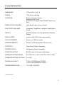
Specifications
Warranty
51
52
2
INTRODUCTION
THE TM ELECTRONICS PACKAGE TESTING SYSTEM
Evaluation of the integrity of a sealed package (porous or non-porous) by inflating it to
its point of failure, the BURST TEST, has been a test standard in the packaging industry
since 1980. Porous and non-porous packages alike have been tested using the CREEP
TEST. In the past, most package test instruments have been able to perform these
basic tests. Now, with the arrival of the BT-1000, additional testing can be done on each
package. A LEAK TEST, and a CREEP TO FAILURE TEST along with four dual tests –
CREEP/BURST, CREEP/LEAK, LEAK/BURST, and LEAK/CREEP TO FAILURE have
been added to increase the value of your BT-1000.
Automatic operation of the principal test setup parameters – pressure and flow – has
been added to increase the accuracy and repeatability of your BT-1000. Repeatability of
the burst and creep test is also improved by refining the method used to introduce air
pressure into a sealed package. Air leakage around the probe entry is eliminated with a
patented device that seals the entry probe to the package by means of an adhesive
disc. The PACKAGE PORT provides a consistent, repeatable input of air to your test
sample, and is the fundamental factor allowing the BT-1000 to perform a leak test.
3
FEATURES OF THE BT-1000
The BT-1000 is a versatile package test system designed to test various sizes and
styles of packages. Some features of the BT-1000 are:
•
Burst test, Creep test, Creep to Failure test and Leak Test.
•
Dual tests – combining tests gives you a better picture of the quality of the package
being tested by testing the package using two different methods.
•
Statistics are included, showing X-bar and R control charts as well as a histogram on
the display.
•
Multiple displays, including statistics, plotted test results, large numerical results, and
a datalog display, give the operator or quality team as much information as possible
about the packages being tested.
•
RS-232-C communication combined with a computer lets you save all the test data
on a computer’s disk drive for future processing.
•
Key lock – Locking the set-up parameters during a test run is important to prevent
any inadvertent changes.
•
Simplicity is designed into the BT-1000 by using a familiar ATM format that guides
you through each step in every test.
•
Test datalog – the result of the previous one thousand (1000) tests are stored in
non-volatile memory and can be listed on the display or printed.
4
EXPLANATION OF TESTS
BURST TEST – CREEP TEST – CREEP TO FAILURE TEST – LEAK TEST
Burst testing is the standard test for a TM Electronics BT-1000. However, to understand
more about the integrity of the package being tested, our BT-1000 is also equipped with
a CREEP TEST, CREEP TO FAILURE, and LEAK TEST. The availability of these four
test modes is extremely useful due to the variety of packages being tested and the
different parameters to be met. See ASTM F-1140 Test Method for Burst and Creep
Tests or ASTM F-2054 Test Method for Burst and Creep Testing Using Restraining
Plates.
Burst Testing: This form of test pressurizes a package to its failure point. This is
accomplished by presetting the pressure and flow to a point above the point of failure.
Creep Testing: This form of test holds the pressure on a package for a given time. A
package that bursts during this test is considered a failure. A package that does not
burst during this test is acceptable.
Creep to Failure: This form of test holds the pressure on a package until the seal
peels apart and fails. The “time to failure” becomes a measure of the seal strength.
Leak Test: This form of test pressurizes a package to a given pressure and stabilizes
the package for a given period and then monitors the pressure decay inside the
package. A pre-determined pressure decay determines the acceptability of the package.
It is important to examine the tested package after a burst test, creep test, creep to
failure test or a leak test. Thoroughly checking where the seal broke or the package split
gives a better idea of where the stressed points are. To test a package properly, a burst
test, a creep test and a creep to failure test should be performed. These tests can be
performed on porous or non-porous packages. On non-porous packages a leak test can
be added.
Using the patented TME Package-Port
: The Package-Port was invented by TME
to enhance the repeatability of testing many package materials as well as to make
possible the pressure decay leak test for non-porous material packages.
Using the TME Closed Package Probe: The Closed Package Probe is designed to
use with the TME Package-Port. CAUTION: When using the Closed Package Probe,
the package must be rotated 90-180° after penetration of the package to prevent the
cut flap from blocking the sensor tube (see Appendix C).
5
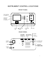
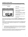
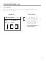
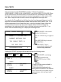
INSTRUMENT CONTROL LOCATIONS
FRONT PANEL
T M ELECTRONICS
BT-1000
TEXT PORTION
OF SCREEN
+
-
GRAPHICS
PORTION
OF SCREEN
ACCEPT
REJECT
*
* / START
KEY
#
/ FUNCTION
KEYS
# / RETURN
KEY
KEY LOCK
REAR PANEL
- PRINTER
CUSTOMER
AIR SUPPLY
CONNECTOR
DATA CONTROL
INPUT/OUTPUT
PORTS
- RS-232
- ACCESSORY
POWER
POWER
SWITCH
…………
…………
FUSE
…………
…………
…………
…………
AIR FEED LINE
TO FIXTURE
PRESSURE
SENSING LINE
FROM FIXTURE
POWER
CORD
6
CONNECTORS
Refer to “INSTRUMENT CONTROL LOCATIONS” for location of the parts
mentioned below.
AIR SUPPLY CONN:
Pneumatic
Compressed air inlet to the instrument – standard fitting
for plastic tubing of ¼” O.D.
Note: The BT-1000 can use either air or nitrogen. It must be clean, dry and
instrument quality. The recommended input pressure is between 90 and 150
PSIG, at 8-10 CFM capacity.
AIR FEED LINE:
Pneumatic
Air outlet, to be connected to the part(s) to be tested via a
3/8” tube and a standard fixture. Standard: 3/8” Male Quick
Connect (Colder).
PRESSURE SENSING:
Pneumatic
Connection of the transducer to the part(s) line
to be tested via a 5/32” tube and a standard fixture.
Standard: Male Quick Connect (Colder).
PRINTER:
Electrical
Printer output connection.
Interface:
Centronics
Type:
DB-25 female
RS232:
Electrical
Serial port input/output connection.
Interface:
RS232-C
Type:
DB-25 male
ACC:
Electrical
Accessories control connection.
Interface:
Proprietary
Type:
DB-25 female
POWER CORD:
100-125 VAC / Grounded plug.
CONTROLS
POWER SWITCH:
Turns instrument ON/OFF.
KEY LOCK:
Locks key pad to prevent parameter or datalog changes (the
open lock symbol indicates that keypad is UNLOCKED, and
the closed lock symbol indicates it is LOCKED).
ACCEPT LIGHT:
Indicates when the result of a Creep or Leak test is a PASS
or ACCEPT.
REJECT LIGHT:
Indicates when the result of a Creep or Leak test is a FAIL or
REJECT.
Note: No pass/fail criteria can be input for the Burst or CTF tests.
7
KEY PAD
* / START
This button starts a procedure or returns to menu from a
secondary screen.
< / CONTROL
1.
2.
+ / UP ARROW
Raises the values of parameters when in the specific test
set-up procedure.
• When pushed once, the number will advance one step
per push.
• When held, the number will quickly count up ten (10)
steps. At that point, the cursor will advance to the next
digit and count up ten (10) steps. This will proceed until
the last digit and the maximum reading is reached.
!
!
When pressed in ready mode, accesses the TEST DATA
MENU screen.
When pressed in certain setup procedures will move
indicator arrow up.
While in the datalog viewing screen, will scroll the data up
!
Lowers the values of parameters when in specific test
procedures.
• When pushed once, the number will advance one step
per push.
• When held, the number will quickly count up ten (10)
steps. At that point, the cursor will advance to the next
digit and count up ten (10) steps. This will proceed until
the last digit and the maximum reading is reached.
While in the datalog viewing screen, will scroll the data down
!
- / DOWN ARROW
# / RETURN
Indicates a choice in the items displayed on an
associated screen.
Activates the HELP screen in the “Ready” mode.
Returns procedure to MAIN MENU screen, or the “Ready”
screen in some menus.
8
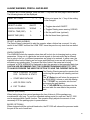
INSTALLATION
UNPACKING:
After taking the system out of its carton, make sure that the
following parts are present:
•
•
•
•
•
•
The BT-1000 instrument.
Air supply tube (1/4” PE tubing).
Instrument/fixture dual connection tube (3/8” and 5/32”
dual tubing) – if supplied with a fixture
Keys (2)
Calibration Certificate
Options (if ordered):
- TS-01 – Open Package Test Fixture
- TS-02 – Closed Package Test Fixture
- One set of Package Ports (included only with TS-02
Fixture)
- One roll of 1000 discs – Package Port Adhesive
(included only with the TS-02 Fixture)
Consult with the factory for missing or damaged parts.
LOCATION:
The BT-1000 should be installed in an environment with
moderate temperature, humidity and static electricity. Keep
away from strong RF or electromagnetic interference or
machinery that generates large line voltage spikes.
CONNECTION:
Connect the power cord of the instrument to a three prong,
120 volt AC outlet.
Connect the enclosed air hose from the “AIR SUPPLY” port
to a compressed air outlet. The air must be “instrument
quality”, free of moisture, oil and dust, and at a pressure
between 90 and 120 PSIG.
Note: The warranty DOES NOT APPLY to failures due to poor quality air supply.
9
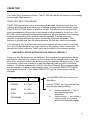
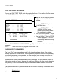
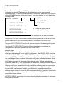
POWER UP
Turn on the BT-1000 by using the power switch located on the back of the instrument.
The instrument starts its automatic self-diagnostic test, the following message will be
displayed:
************************
*
T. M. ELECTRONICS
*
*
*
*
BT-1000-50 V5
*
************************
DATE
TIME
INITIALIZING SENSORS 60.0
During this time the ACCEPT and REJECT lights are kept ON to verify that they are
operational. After the initialization, it is possible that the instrument will display an error
message. Should this happen, call TM Electronics at (508) 856-0500 for technical
support.
After the initialization is complete, the BT-1000 will display the first MAIN MENU screen.
This signals that the instrument completed all the internal diagnostics and is ready to
start testing.
10
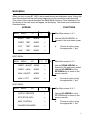
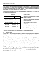
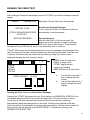
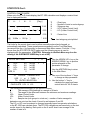
MAIN MENU
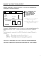
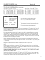
When you turn on your BT-1000 it will proceed through an initialization cycle. During this
time the instrument will be performing diagnostics on its pneumatics and electronics.
This portion of the manual describes the MAIN MENU functions. After initialization the
first screen of the main menu will appear on the display. The screen and functions are
illustrated below.
SCREEN
MAIN
MENU
FUNCTIONS
#
\/
1/3
BURST
TEST
MODE
<
CREEP
TEST
MODE
<
C/T/F
TEST
MODE
<
LEAK
TEST
MODE
<
Main Menu screen 1 of 3
Use the DOWN ARROW/- to
proceed to the next menu screen
a.
Choose an option using
the appropriate ‘<’ key.
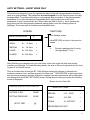
NEXT MENU:
MAIN
MENU
\/ /\
2/3
#
#
Main Menu screen 2 of 3
CREEP + BURST
MODE
<
CREEP + LEAK
MODE
<
LEAK + BURST
MODE
<
Use the DOWN ARROW/- to
Proceed to the next menu screen
Use the UP ARROW/+ or the
RETURN/# sign to return to the
previous screen.
LEAK + C/T/F
MODE
<
a.
Choose an option using
the appropriate ‘<’ key.
NEXT MENU:
MAIN
MENU
3/3
/\
#
#
Main Menu screen 3 of 3
OUTPUT REPORTS
<
STATISTICS DATA
<
Use the UP ARROW/+ or the
RETURN/# sign to return to the
previous screen.
MISC. CONTROL
<
a.
CALIBRATION MODE
<
.
Choose an option using
the appropriate ‘<’ key.
11
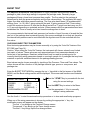
BURST TEST
The objective of the Burst Test process is to supply adequate back pressure inside the
package to yield a force large enough to separate the package seals. Generally, larger
packages will have a lower burst pressure than smaller. The flow rate into the package is
determined by both the pressure regulator and the flow valve settings. The regulator will supply
higher flow rates with higher pressure settings. The flow valve has sixteen (16) predetermined
settings (from 1 to 16), with 1 giving minimum flow and 16 giving maximum flow. Timer values
control the maximum amount of time that the Burst test will run. Typical burst tests may run 0.5
to 10 seconds depending on materials and size. When pressure and flow parameters have been
established the Timer is usually set at two times the average time to burst.
For porous materials, the internal back pressure is a function of input flow rate of air and the flow
rate out of the package due to material porosity. Non-porous materials do not leak air, therefore
the internal back pressure can be controlled with the regulator and fill rate controlled with the
flow value.
CHOOSING BURST TEST PARAMETERS
Burst test setup parameters may be chosen manually or by using the “Auto-Set” feature of the
BT-1000 (see Page 14 ).
Caution: When using the “Auto-Set” feature, the instrument will choose values from a limited
test matrix of values. These values are only approximations of test parameters based on a
limited set of test packages. Resultant values should only be used as a starting point for
correctly identifying setup parameters based on running a sample lot of packages that may have
materials or process variables inherent in the package sealing process.
Burst values may be chosen manually by inputting of the Pressure, Timer and Flow values. The
values chosen will be a function of the package material type, porous or non-porous, and
package size.
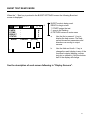
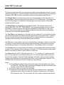
Enter the BURST TEST MODE by pressing the top ‘<’ key while in the first screen of the MAIN
MENU, and the Burst settings screen will be displayed. The screen and functions are illustrated
below:
BURST SETTINGS
*
PRESSR
:
0.0 PSIG
TIMER
:
0.0 SEC.
FLOW
:
0 {POROUS}
PROGRAMS/AUTO-SET
#
<
<
<
<
Use the */START Key to proceed with the test
using the current settings.
Use the #/RET Key to return to the Menu.
Use the appropriate ‘<’ Key to manually
change a setup parameter.
Use the fourth ‘<’ to start the automatic setup procedure or to store and recall setup programs.
When one of the setup parameters is chosen by pushing the appropriate ‘<’ key, the
modification screen will appear on the display.
The first ‘<’ key brings up the Pressure Change screen.
The second ‘<’ key brings up the Timer change screen.
The third ‘<’ key brings up the flow change screen.
BURST TEST (Continued)
The fourth ‘<’ key will enable the PROGRAMS/AUTO-SET function.
The parameter change screen is described on Page 16.
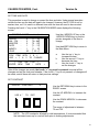
Determining Parameters for Non-Porous Materials
When testing non-porous materials, the Burst test settings can be determined by starting at midrange, i.e. pressure = 25 psig, flow = 8, and timer setting of 5 seconds. After running one test,
view the “Test Plot” screen and compare your results to the examples below:
*
*
PRESR.
*
*
* ** *+
+
+
*
*
*
*
*
* * * * > TIME
****** *
*
*
*
*
*
*
*
** +
+
+
+ * * * * > TIME
*
PRESR.
The Ideal Burst Curve
The pressure ramps up at a constant rate
(typical for non-porous materials).
**Pressure/Flow settings are correct.
The Delayed “Burst” Curve
The pressure leveled off at a value for
a significant percentage of the test
time, then a “burst” occurred.
**Increase pressure and/or flow.
PRESR.
**
**
**
**
**
* * ** * * * * * * * * * * * * > TIME
The Sharp “Burst” Curve
The pressure curve rises steeply
followed by a burst (typical for non-porous
materials).
**Decrease flow for non-porous materials.
Repeat this process until you achieve a plot resembling the ideal burst curve shown above.
Timer values can be adjusted to scale the plot to a typical 2-3 second burst time. Set the timer to
approximately twice the burst time.
Determining Parameters for Porous Materials
For porous materials, the selection of Pressure and Flow values is chosen based on the porosity
of the package materials and the area of the porous material. Remember that, in principle, more
air must flow into the package than flows out of the porous wall to allow a back pressure to
develop inside the package.
Selecting a pressure and flow setting for porous packages generally depends on package
porous material area. For small packages (less than 16 in2 porous materials) a pressure setting
of 20 psi and flow setting of 10-12 might burst the package consistently. Burst timer, as seen on
the “Test Plot” screen, should be greater than 0.5 seconds. An initial timer setting of 5 seconds
13
BURST TEST (Continued)
can be tried first. If burst times are too short, then decrease flow values. If burst times are too
long or the timer says “TOVR”, then increase flow rates to maximum in steps or increase
pressure value above the 20psi level to increase the regulator output flow.
For larger packages (64 in2 or above), a setting of 50psi can be tried first with flow values at f =
8. Again, decrease flow or pressure values if the burst time is too short (less than 0.5 seconds)
or increase flow values, in steps, if burst time is too long or the timer says “TOVR”.
Note: Porous barrier materials will vary even within lots of packages. When testing porous
barrier packages several samples should be run to determine that 90% or more packages will
burst on testing.
14
PARAMETER CHANGE SCREEN
This procedure is used throughout the BT-1000. Any time a parameter needs to be changed,
this screen will be displayed. Push the top ‘<’ key to access the following screen. The screen
and functions are illustrated below.
SCREEN
BURST
MAX.
TO CHANGE #
USE #
TO EXIT
UNITS:
a.
Use the second ‘<’ key to change the
Display units.
b.
Use the UP ARROW/+ to increase the
maximum burst pressure available to
burst the package.
c.
Use the DOWN ARROW/ - to decrease
the maximum burst pressure available.
d.
Use the RETURN/# key to return to the
SETTINGS screen.
e.
The cursor line will be below the digit
being changed.
PRESSURE
USE /\ \/
*
FUNCTIONS
< P.S.I.G. >
<
Using this screen is very simple. The UP arrow key increases the parameter while using the
down arrow decreases the parameter. Either the * / START or the # / RETURN key will exit the
screen. The final number displayed on the screen when exiting will be the set point for the
parameter.
Changing the units in the pressure change screen is the same procedure as changes in the flow
change screen. In the pressure change screen pressing the second ‘<’ key will toggle between
In. H2O and PSIG. In the flow change screen, pressing the second ‘<’ key will toggle between
porous and airtight modes.
NOTE:
1.
2.
3.
The maximum pressure available is 50 PSIG (1384 In. H2O) or 100 psi for BT-1000-100.
The flow settings are numerical reference points to allow you to return to the same setting
easily. There are sixteen (16) different flow settings (note: 1 is low flow, 16 is high flow).
The maximum time available is 999.9 seconds.
Combinations of pressure regulator and flow number settings will provide a continuous scale of
output air flow to the package. Once a combination of pressure and flow settings is chosen the
instrument will repeat the output air flow each time that combination is used.
15
PROGRAMS/AUTO-SET
Once the setup parameters have been established by the instrument or the operator, the option
of storing them in non-volatile memory is available. Up to ten different programs can be stored
for each of the eight (8) different test modes. In addition, a function designed to find the BURST
setup values for a package has been built into the BT-1000
Choosing the PROGRAMS/AUTO-SET option will display the following screen. The screen and
its functions are illustrated below.
SCREEN
FUNCTIONS
BURST SETTINGS
/\
\/
RECALL PROGRAM
#0
<
STORE PROGRAM
#0
<
AUTOSET :
AIRTIGHT
<
AUTOSET :
POROUS
<
#
Use the ‘ /\ ‘ key to increase the program
number to be used.
Use the ‘\/’ key to decrease the program
Number to be used.
Use Pound key to return to BURST
SETTINGS screen.
a.
b.
Use the first ‘<’ key to recall a
program.
Use the second ‘<’ key to store
a program.*
*Note that a program number must be selected first to store or recall a program.
C.
Autoset : Airtight
Use the third ‘<’ key to automatically find and set the BURST parameters for airtight packages.
Airtight packages are those that are not breathable, usually made of films, foils or laminates.
D. Autoset: Porous
Use the fourth ‘<’ key to automatically find and set the BURST parameters for a POROUS
package. Porous packages are those that are breathable. Generally porous packages contain
sections made from materials that allow the passage of air (Tyvek or paper). The amount of air
flow to burst a porous package depends on the porosity and area of the breathable surface. The
“Auto-Set” mode has a limited matrix to determine package test parameters. Once a group of
settings is determined, several more packages should be tested to optimize the test parameters
to achieve the typical burst curve and determine materials consistency for those test
parameters.
NOTE:
When storing a program, the current setup parameters become the program
parameters for that specific program number. ANY PREVIOUS PARAMETERS SAVED IN
THAT PROGRAM NUMBER WILL BE LOST. Also, when a program is recalled the
program parameters become the current parameters, and ANY PREVIOUS SETUP
PARAMETERS WILL BE LOST.
16
AUTO SETTINGS – BURST MODE ONLY
This function is designed to give the operator an idea of what the setup parameters should be
used on a given package. The parameters are not designed to be the final set points for every
package tested. They may work better on one package than on another. If the recommended
parameters do not give a precise and repeatable burst, simply adjust one or all of the
parameters to give a more precise test. When either the third or fourth ‘<’ key is pressed the
program moves into the automatic parameter setting feature, and the following screen is
displayed. The screen and its functions are illustrated below.
SCREEN
Auto Settings screen
#
ENTER ROUGH SIZE
SMALL
FUNCTIONS
:
A<
16 Sq In.
<
MEDIUM :
A<
64 Sq In.
<
LARGE
:
A< 144 Sq In.
<
XLARGE :
A< 400 Sq In.
<
Use #/RETURN to return to the previous
screen.
a.
Choose a package size by using
the appropriate “<” key.
After attaching your package onto your test fixture, select the rough size that most closely
matches your package. To make estimating easier, the area of the pouch (physical size) is used
in place of its internal volume.
Once a size has been chosen the BT-1000 will begin testing the package to estimate the
maximum pressure, time, and flow required for a burst test. TWO MINUTES is the longest time
this auto-setup procedure will take, and when complete, the setup parameters will be calculated
and displayed in the BURST SETTINGS screen. During the auto-setup procedure the following
screen is displayed:
Screen at end of Auto-Set:
POROUS (AIRTIGHT) AUTO SETUP
SETTING FLOW
BURST SETTINGS
*
#
:
DONE
PRESSR
:
5.15
SETTING PRESSURE :
DONE
TIMER
:
47.4 SEC
<
FLOW#
:
10 AIRTIGHT
<
SETUP TEST
:
@
PROGRAMS/AUTO-SET
PSIG
<
<
17
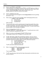
BURST TEST READY MODE
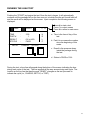
When the * / Start key is pushed in the BURST SETTINGS screen the following Burst test
screen is displayed.
BURST
PART#
E-TIME
RESULT
STATUS
BURST
*
READY
* /\ #
:
:
:
:
PRESSR.
H
E
L
P
#
BURST mode is being used.
READY to begin a test.
*/ START begins the test.
/\ goes to the Datalog
# / RETURN returns to main menu
a.
Use the first or second ‘<’ key to
display the help screen. The Help
screen shows test parameters and
directions on moving to output
screens.
b.
Use the third and fourth ‘<’ key to
change the result display to any of the
functional outputs (datalog, counter,
test plot or statistics). Only the bottom
half of the display will change.
[In H2O]
See the description of each screen following in “Display Screens”.
18
DISPLAY SCREENS
When the BT-1000 is in the “ready” mode of any test (see the above screen) the operator will be
able to change the result display by pushing either of the bottom two “<” keys. The third key
scrolls through the display styles in one direction, and the fourth key scrolls through the styles in
the reverse direction. There are eight different result displays accessible. They are:
1.
A LARGE NUMERICAL READOUT
-
one inch tall display of the test pressure
2.
THE TEST RESULT COUNTERS
-
totals of the test results
3.
A GRAPHIC TEST PLOT
-
an X-Y PLOT of pressure vs. time
4.
A DATALOG LISTING
-
a listing of the last eight test results
stored in the Datalog
5.
STATISTICAL DATA
-
Mean (AVG), MIN, MAX, STANDARD
DEVIATION, and RANGE
6.
HISTOGRAM
-
A five bar histogram (± 3σ range)
7.
_
AN X CHART
-
_
A running X-chart of the results
8.
AN R CHART
-
A running R-chart of the results.
HELP SCREEN
{
3:00 PM
PRESSR
TIMER
FLOW
PROG.
‘*‘ :
‘#‘ :
‘+‘ :
:
:
:
:
6/1/93
10
3
4
1
}
PSIG
SEC.
{ POROUS }
TO START TO TEST
TO EXIT TO MAIN
DATALG/STATS/REPORTS
A help screen, shown here, is provided to
display the time, date, and setup
parameters, as well as a reminder of the
function of the main keys. It is accessible
any time the display is in the READY state
by pressing either of the top two ‘ < ‘ keys.
‘ < ‘ 3&4 : CHANGE DISPLAY MODE
1. You must hold down the HELP < key to continually view the screen.
2. When using the # key the program returns to the Main Menu. The “Test Plot” of the last
test will be erased when you exit. If the “Overwrite Warn” feature (see Page 40) is NOT
engaged, then ALL TEST DATA IN THE DATALOG WILL BE ERASED when returning
to the “Ready” mode.
3. Use the “+” (up arrow) key to Print or View (output) data to avoid using Main Menu.
4. Printed output of the Datalog, statistics and charts are accessed directly from the “Ready”
mode using the “+” (up arrow) key. The datalog can be downloaded via the RS232
port to an attached computer.
19
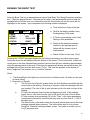
RUNNING THE BURST TEST
Once the Burst Test set up parameters are entered (see Burst Test Setup Procedure), pushing
the * / Start key begins the test. Once the test is begun, it will automatically continue until the
package fails or the time runs out, at which time the air flow will shut off and the result will be
displayed on the screen. Upon completion the following screen is displayed.
a. Time is the time of day of the test.
BURST
PART#
E-TIME
RESULT
STATUS
BURST
READY
:
:
:
:
1
* /\ #
3:00p
65%
35.0 In H2O
BURST
PRESSR.
[In H2O]
H
E
L
P
b. Part# is the datalog number since
the beginning of this series.
c. E-Time is a percentage of the “time”
Setting in test parameters
d. Result is the maximum pressure
reached in the package prior to
failure with the chosen units of
measurement.
e. Status is Burst or time over (Tovr)*.
Pressing the */START key again begins the test without returning to any other menu screen.
During the test a line will expand along the bottom of the screen. This is a time line. If the burst
occurs prior to the time standard being reached, the time line will stop, indicating approximately
when the package burst in the cycle. If the time line expands all the way across the screen, the
package has not burst and the time is over (T-Ovr). This time line appears on the bottom of
every “single-test” test screen, not on “dual test” screens.
Notes:
1. The Accept/Reject limit lights are not functional in the Burst mode. No limits can be input
for burst values.
2. Description of Results:
a.
The first line of the Results screen shows the Part Number associated with the
current test in the datalog. (If tracking is required, mark each package with this
part number). The time of day is also indicated on this line and is stored in the
datalog.
b.
E-Time is the elapsed time from the test beginning to end. If the package
bursts, then it is the time from the start of the test to the time it took to burst.
E-Time is shown as a percentage (%) of the “Timer” in the setup parameters
(see previous discussion) since the test may have any time from 0.1 – 999.9
seconds input.
c.
The Result value is the tested value for the peak internal pressure at which the
package ruptured (burst pressure). The value will be read in units chosen
during the “Pressure” setup parameter screen. This value is usually in psi or
In H2O pressure units.
20
RUNNING THE BURST TEST (Continued)
d.
The status reading is either “Burst” or “T-ovr”. A Burst value indicates that the
package ruptured and was recorded before the “Timer” setting elapsed, or
timed out. A value of “T-Ovr” indicates that the package did not rupture (burst)
before the “Timer” setting elapsed. A “T-Ovr” value is an invalid test. The data
shown will not be used in statistical calculations, although the data will be
recorded in the datalog.
3. Using the Test Plot Screen
One of the eight data output screens is the “Test Plot”. This screen is one of the most
powerful tools available in the BT-1000 instrument. The Test Plot screen shows the actual
result of Pressure and Time reaction inside the test package volume. Using the Test Plot an
operator can determine:
1.
The peak pressure at Burst
2.
The time to burst
3.
The fill rate of the package to burst
4.
If the test is a delayed burst
5.
The characteristic curve of a set of package materials and process conditions
6.
If the seal has multiple seals, an observation of each burst pressure can be made.
The Test Plot is an efficient tool to aid in establishing Pressure and Flow parameters in new
packages. The Test Plot can be printed and used to compare packages in different lots or
compare characteristics for trouble-shooting process condition changes.
21
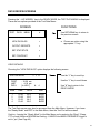
DATA REVIEW SCREENS
Pressing the ‘ +/UP ARROW ‘ key in the READY MODE, the TEST DATA MENU is displayed.
There are four options provided in the Test Data Menu:
SCREEN
TEST
DATA
FUNCTIONS
MENU
#
Use RETURN/# key to return to
the previous screen.
VIEW DATALOG
<
a. Choose an option using the
appropriate “<” key.
OUTPUT REPORTS
<
SET STATISTICS
<
SET CONTRAST
<
VIEW DATALOG
Choosing the “VIEW DATALOG” option displays the following screen:
TEST DATALOG
FIRST
LAST
DATA
/\ \/ #
: 10:26 am
: 4:18 pm
[ In H2O ]
Use the “/\” key to scroll up.
Use the “\/” key to scroll down
#:
4
NUM
TIME
DATA
RSLT
1
2
3
4
10:26
10:28
10:35
10:45
65.5
65.0
64.5
66.0
BURS
BURS
BURS
BURS
Use “#” key to return to the
READY MODE.
The Test Data screen may also be accessed from the Main Menu. However, if you leave
the “Ready Mode” and EXIT to the Main Menu, then the Test Plot will be erased.
Caution: Leaving the “Ready Mode” to the Main Menu and re-entering the “Burst” (Creep,
CTF or Leak) Mode will ERASE the Datalog – UNLESS the WARN OVERWRITE toggle is
set to “yes” (see Page 40).
22
DATA REVIEW SCREENS – Cont.
OUTPUT REPORTS
(See Caution for Data Review Screens on previous page)
To facilitate record keeping, the BT-1000 is equipped to send the test results and other
information to an attached, compatible printer or to the RS232 port.. Test results will be
sent automatically to the printer or output to an attached computer through the RS232 port.
To output other stored data use the following screen:.
SCREEN
OUTPUT REPORTS
FUNCTIONS
Output Reports screen.
#
Use the #/RETURN Key to return
to the MAIN MENU screen.
OUTPUT LAST TEST
<
OUTPUT SETTINGS
<
OUTPUT DATALOG
<
OUTPUT STATISTICS
<
a. Choose an option using
the appropriate “<” key.
Using the OUTPUT LAST TEST function sends the results of the last test to the printer. If
the BT-1000 is in test plot mode, the last test result will be followed by a printed plot of the
test curve.
Using the OUTPUT SETTINGS function sends the setup parameters and program number
of the current test to the printer.
Using the OUTPUT DATALOG function will send the contents of the datalog to the printer.
Using the OUTPUT STATISTICS function will send the statistical calculations, the
Histogram, the X-Bar chart, and the R chart to the printer.
23
DATA REVIEW SCREENS – Cont.
SET STATISTICS
The BT-1000 offers statistical operations that can be either manually entered and changed,
or automatically calculated. These operations are accessed from the “Test Data Menu”
using the + up arrow in Ready mode or the second Main Menu screen. Push the “<” key
across from the STATISTICS DATA option and the following screen will be displayed. See
Caution for Data Review screens.
STATS. SETTINGS
X UCL:
X LCL :
R UCL:
R LCL :
SIZE,N
0.0
0.0
0.0
0.0
0
/\
\/
In H2O <
In H2O
In H2O
In H2O
#
<
TO
CHANGE
PARAMETERS
USE /\ OR \/ THEN <
TO
ENTER
SELECTION
CALCULATE UCL & LCL
Use the ARROW UP/+ key or the
ARROW DOWN/- key to position pointer
alongside of the parameter to change.
Use the #/RETURN Key to return to the
“Ready” screen or Main Menu
a. Use one of the top three “<”
keys to manually change a
setup parameter.
b. Use the bottom “<” key to
calculate the upper and lower
control limits for X & R charts from
the current datalog set.
The following definitions apply to the previous screen:
X
R
-
UCL
LCL
N
-
The average of the readings in a sample of N tests.
The Range of the difference between the minimum and maximum
readings.
Upper Control Limits
Lower Control Limits
Sample Size (or sub groups in a test run for the Control Charts).
The modification screen for the statistics settings is the same as the modification screen for
the Burst test settings. If you need to review it, see the BURST TEST SETUP
PROCEDURE.
_
The sample size is the number of tests averaged to determine one point on the X or R
control charts. Every test result is recorded in the datalog, and the averages are calculated
based on the sample size, N. A maximum of 20 samples are allowed.
The LCL or UCL can be entered or changed manually based on operator calculations, or
the BT-1000 can calculate the LCL for them. The BT-1000 calculations are based only on
the test results stored in the datalog. Each point of the X and R chart is an average of the
number of tests.
24
DATA REVIEW SCREENS – Cont.
SET CONTRAST
The contrast of the screen can be adjusted for ease of reading. The screen and its
functions are illustrated below.
SCREEN
DISPLAY CONTRAST
USE /\
USE
\/
# *
TO CHANGE
TO EXIT
FUNCTIONS
#
#
a. Use the RETURN/# key to
return to the READY screen.
b. Use the UP ARROW/ + to
increase the contrast
(maximum value 125).
c. Use the DOWN ARROW/- to
decrease contrast.
25
CREEP TEST
The Creep Test is a pressure hold test. The BT-1000 will hold the set pressure on the package
for the length of time selected.
CREEP TEST SETUP PROCEDURE
The BT-1000 can test both porous and non-porous packages. When setting the flow, the
operator will tell the instrument which style of package is being tested by setting the toggle
in the “FLOW SETTING” screen to porous or air-tight. This adjustment is more critical for
porous packages since the porosity of the package is being matched by the air flow. If the
BT-1000 cannot consistently hold the selected pressure, the flow may need to be increased
or decreased depending of the pressure inside the package. If the test pressure is
generally more than the entered pressure, the flow may need to be decreased. If the
pressure is generally less than the entered pressure, the flow may need to be increased.
If the package is very large, the creep test pressure required will be very small, causing the
air to flow into the package at a very slow rate due to the regulator output characteristic. To
decrease the fill time required a “Prefill” option can be added to the instrument controls.
(SEE PREFILL SETUP INSTRUCTIONS IN “DISPLAY CONTROL”)
There is no Auto-Set program for the creep test. This is because the operator must decide
how long the creep test is to continue, how much pressure the package needs to see, and
what flow is required to optimize the pressure for a given package size and porosity. To set
the pressure, a good rule of thumb is to start the creep test pressure at 80% of the Burst
pressure. Not all seal materials will hold 80% of the Burst Pressure. Some experimentation
may be required to establish a creep pressure value. To choose the CREEP TEST MODE
option, push the second “<” key labeled CREEP TEST and the following screen will be
displayed.
CREEP SETTINGS
*
#
PRESSR
:
0.0 PSIG
<
TIMER
:
0.0 SEC.
<
FLOW
:
0 {POROUS} <
PROGRAMS
<
Use the #/RETURN Key to return to the
Main Menu.
Use the */START key to proceed with the
test using the existing settings.
a.
b.
Use the appropriate “<” key to
manually change setup
parameters
Use the bottom “<” key to store a
setup program, or to recall a
previously memorized program.
26
CREEP TEST (Continued)
When setting the creep test parameters the same setup procedure is used as when setting
the Burst test parameters. To refresh your memory, see “BURST TEST SETUP
PROCEDURE”.
NOTE: The pressure and time values are selected by the user according to his/her own
validation requirements. The “Creep Test” is a pass/fail test. If the package does not
rupture before the end of time cycle, a “Pass” light will illuminate. Conversely a drop in
pressure will signal a “Reject” light.
27
RUNNING THE CREEP TEST
After setting the Creep test parameters, push the */START key and the following screen will
appear.
PRESET
PARAMETERS
SETTING FLOW
:
ATTACH PACKAGE AND PRESS
START KEY :
Setting the Flow will take only a few seconds.
Non-Porous (Airtight) Packages:
In the non-porous mode, the instrument will move
automatically to set the pressure.
Porous Packages:
After the flow is set, in the porous mode, the
display will ask the operator to attach a package
and press start. During this time the BT-1000 is pre-setting the pressure. This procedure
can take as long as 30 seconds, but it is only necessary once in a test run.
SETTING PRESSURE :
If the BT-1000 cannot set the desired pressure on a porous package using the entered flow
rate, three beeps will sound, indicating that the flow rate must be increased. If the flow rate
is optimal, the pressure will be preset, and the following Creep Test screen will be
displayed indicating the test is ready to begin.
CREEP
PART#
E-TIME
RESULT
STATUS
READY
*
:
:
:
:
CREEP PRESSR.
/\
#
H
E
L
P
[In H2O]
CREEP mode is being used.
READY to begin a test.
*/START begins the test.
/\ goes to the datalog
#/RETURN returns to main menu.
a.
b.
Use the first or second “<”
key to display the help
screen.
Use the third and fourth “<”
keys to change the result
display.
Running the Test: Porous or Non-Porous Packages
Pressing the */START key begins the test. If the display is in NUMERICAL SCREEN, a line
will expand along the bottom of the screen during the test. This is a time line. If a burst
occurs prior to the time standard being reached, the time line will stop, indicating
approximately when the package burst in the cycle. If the time line expands all the way
across the screen, the package has not burst and is acceptable. The test result screen and
help functions are the same as in the BURST MODE. To refresh your memory, see
RUNNING THE BURST TEST.
28
CREEP TEST – Con’t.
The E-Time is the accept/reject deciding factor of the Creep test. If the E-Time is anything
less than 100%, the package has failed. The following results are reported in the STATUS
line after the Creep test is complete:
PASS The package has not failed during the entire test.
FAIL The package opened the seal at some time during the test.
BAD PKG - The package opened the seal prior to reaching the test pressure.
The RESULTS line reports the pressure reached during the test.
The next test is ready to be run again from the results screen. Push */START to begin.
While running the creep test there is bound to be a certain amount of fluctuation in the
reading. This is due primarily to inconsistencies in the package along with the resolution of
the BT-1000. You can expect to hold at least ± 1 inch of water at all times. If there is more
fluctuation than that, the flow may need to be adjusted up or down depending on which
direction the pressure is moving (see CREEP TEST SETUP procedure).
29
CREEP TO FAILURE
The Creep to Failure Test is a pressure hold test similar to the Creep test. However, the
package is pressurized to a predetermined pressure which is then held until one or more seals
fail (the internal pressure will cause the seal to “creep” and open). The “Time to Failure” is a
variable measure of the seal’s shear resistance.
CREEP TO FAILURE TEST SETUP PROCEDURE
During the Creep to Failure test, the package is pressurized to a point that will open a seal
on every package, including acceptable packages. This is done by adjusting the pressure
and flow until the package seals open after the desired amount of time (typically 15 - 30
seconds). The amount of time it takes to creep through the seal determines its strength. A
package that takes the full set time or very close to the full set time is a strong package. A
weakened seal will take somewhat less time to creep through. The amount of time
permissible is based on user evaluations of acceptability.
To choose the CREEP TO FAILURE TEST MODE option push the second “<” key labeled
CREEP TO FAILURE TEST and the following screen will be displayed.
C/T/F SETTINGS
*
#
Use the #/RETURN key to return to the
Main Menu.
Use the */START key to proceed with
the test using the existing settings.
PRESSR
:
0.0 PSIG
<
TIMER
:
0.0 SEC.
<
FLOW
:
PROGRAMS
NOTE:
0 SET#
<
a.
<
b.
Use the appropriate “<”
key to manually change a
setup parameter.
Use the bottom “<” key to
store a setup program, or
to recall a previously
memorized setup program.
There is no Auto-Set program for the Creep to Failure test.
The Creep to Failure test parameters are set using the same procedure as the Burst test.
To refresh your memory, see BURST TEST SETUP PROCEDURE.
Notes:
1. Accept/Reject lights are not functional for the C-T-F- test. No limits on the “Time to
Failure” can be set.
2. Some experimentation is required to establish pressure and time values for the
C-T-F test. A time value of the mean “time to failure” should be set as the center of
the time range. In this way the statistical output charts will be more valuable in
monitoring process trends. Longer “time to failure” indicates stronger seals while
shorter times indicate weaker seals.
30
RUNNING THE CREEP TO FAILURE TEST
When the */START key is pushed in the CREEP TO FAILURE SETTINGS screen the
following Burst Test screen is displayed.
C/T/F
PART#
E-TIME
RESULT
STATUS
READY
:
:
:
:
C/T/F PRESSR.
15.0 SEC.
BURST
[In H2O]
*
/\
H
E
L
P
#
C/T/F mode is being used.
READY to begin a test.
*/START begins the test.
/\ goes to the datalog.
#/RETURN returns to main menu.
a. Use the first or second “<” key to
display the help screen.
b. Use the third and fourth “<” key to
change the result display.
Pressing the */START key begins the test. The test result screen and help functions are the
same as in the BURST MODE. To refresh your memory, see RUNNING THE BURST
TEST.
The following results are reported in the STATUS line after the Creep to Failure test is
complete:
BURST The package has ruptured the seal (burst).
TOVR The package has not burst prior to the end of the test.
BAD PART - The package burst prior to reaching the test pressure.
The RESULTS line reports the time to failure. A shorter time indicates a weaker seal.
The next test is ready to be run again from the results screen. Push */START to begin.
31
LEAK TEST
LEAK TEST SETUP PROCEDURE
Choose the LEAK TEST MODE option by pushing the fourth “<” key while in the first screen
of the MAIN MENU. The following screen will be displayed.
LEAK
SETTINGS
CHARGE
SETTLE
TEST
FINE
PRESS
FLOW
:
:
:
:
:
:
0.0
0.0
0.0
0.0
0.0
0
*
SEC.
SEC.
SEC.
InH2O
PSIG
SET#
/\
\/
#
<
<
TO CHANGE PARAMETERS
USE
/\ OR \/
THEN
<
TO
ENTER
SELECTION
PROGRAMS
<
Use the */START key to proceed
with the test using the existing
settings.
Use the #/RETURN key to return
to the Main Menu.
a. Use the ARROW UP/+ key or the
ARROW DOWN/- key to
position pointer along side of
the parameter to change.
b. Use one of the top three “<” keys
to change a setup parameter
c. Use the bottom “<” key to STORE
a setup program, or RECALL
a previously memorized setup
program.
Refer to “PARAMETER CHANGE SCREEN” (pg. 15) for instructions on how to set a test
parameter.
NOTE:
There is no Auto-Set program for the Leak Test.
CHOOSING TEST PARAMETERS
The “Leak Test” is a pressure decay test for the internal package volume. The choice of
settings depends on several factors, including the size (expanded volume of the package),
the flexibility (materials) of the package, the seal strength (burst or creep value), and the
leak rate to be detected.
Because some flexible packages are designed to peel open, the test pressure chosen for
leak testing should not open or damage the seal bond. Although the user should determine
this pressure, a rule of thumb would keep the test pressure below one third of the burst
pressure value.
The leak rate detected in a pressure decay test is a function of package volume and time of
the test:
∆P(atm) ∗ V (cc)
Q(cc / sec) =
∆t (sec)
32
LEAK TEST (Continued)
The leak rate detected will be most sensitive at smaller internal package volumes. A metal
restraining plate fixture to restrict package movement (prevent ballooning) will increase test
sensitivity. Call TME for further information on the use of restraining plate fixtures.
The Charge Timer is set depending on the size of the package and the flow value. For
most packages at low test pressures a flow value of 12-16 usually works. The Charge time
must be long enough to completely fill the package to the setup pressure (Press) with
several seconds to spare.
The Settle Timer is set depending on package flexibility. The package volume must
stabilize BEFORE THE TEST TIME BEGINS. An expanding package will show a decay
(decrease) in internal pressure that might be interpreted as a leak when no leak really
exists. The pressure reading on the display during the Settle time should not decrease
more than one or two least significant digits.
The Test Timer is set depending on the leak rate to be detected. From the above equation,
one can see that longer test times provide the opportunity to find smaller leaks. However,
the use of long test times may not be practical due to material flexibility or temperature
changes in the environment, which will affect pressure values.
The Fine value is the pressure decay limit allowed before a package is said to have a leak.
This value is chosen based on the pressure and time settings (discussed above) and an
actual leaking package or a theoretical calculation or flow standard used in the system.
The Pressure value is chosen based on the ability of the package (and restraining system,
if used) to hold a pressure without damage to the seals. The Pressure may also be chosen
based on the ability to detect a given leak size or leak rate.
The Flow setting for the BT-1000 can be set from 1 – 16. A setting of 1 restricts the flow
rate from the regulator to small flows and a value of 16 does not appreciably restrict the
flow from the regulator. Generally flexible packages will require lower pressure regulator
settings, which will therefore have small output flows. Using a higher flow setting of 12-16
will allow faster fill rates and minimize Charge time requirements.
Notes:
1. The Accept/Reject indicator lights will function along with the audible alarm during
the Leak Test. The Reject light and Alarm will engage if the pressure decay value
meets or exceed the Fine leak setting limit.
2. The Test Plot does not function in Leak mode.
3. The datalog will record the decay value at the end of each test time. Large leaks,
called gross leaks, which are rejected in Charge or Settle modes, will indicate
999.9 pressure value. The gross leaks will not be used in statistical calculations.
33
RUNNING THE LEAK TEST
Pushing the */START key begins the test. Once the test is begun, it will automatically
continue until the package fails or the time runs out, at which time the air flow will shut off
and the result will be displayed on the screen. Upon completion the following screen is
displayed.
LEAK
TIME
PART #
RESULT
STATUS
DECAY
READY
:
:
:
:
3.00
1
0.6 In H2O
PASS
PRESSR.
[In H2O]
*
/\
H
E
L
P
#
Press # to start a test
Press /\ to output screen
Press # to return to main menu
a. Time is the time of day of the
test.
b. Part # is a consecutive number
since the beginning of this
series.
c. Result is the pressure decay
inside the package during
the test.
d. Status is PASS or FAIL.
During the test, a time line will expand along the bottom of the screen indicating the time
during each cycle of the test. The line expands all the way across during each cycle. The
location on the top line that has the word “READY” changes as the test proceeds to
indicate the cycle (i.e., CHARGE, SETTLE, or TEST).
34
DUAL TESTS
The second screen of the MAIN MENU provides a selection of dual tests –
CREEP+BURST, CREEP+LEAK, LEAK+BURST, and LEAK+CREEP-TO-FAILURE. Since
all the dual tests have the same format, one test will serve as an example for all of them.
Each dual test uses the current single test setup for its parameters in each section of the
test. Note: Using dual test will result in values that might differ from single tests.
For example, the Creep+Burst test will take the setup from the current Creep test and the
setup from the current Burst test and combine them into the CREEP+BURST test. To set
different parameters for the Creep+Burst test, go into the individual Creep or Burst test
setup procedure and make the appropriate changes. When finished changing the
parameters in the single test format, return to the dual test menu and push the “<” key
across from the dual test being run to display the following screen.
CREEP + BURST MODE
*
#
CREEP+BURST is the name of
the dual test being run.
PRESS “ * “ TO USE THE
Use the */START key to begin the
test.
CURRENT SETTINGS FOR
Use #/RETURN key to return to
the Main Menu.
THE SINGLE TESTS IN
THE DUAL TEST
PROGRAMS/AUTO-SET
a. Use the fourth “<” key to
automatically determine and
set the setup parameters.
<
Pushing the */START key begins the test and displays the following screen.
CREEP
TIME
PART #
BURST
*
:
:
3:00
1
:
:
28.0 InH2O
PASS
:
:
10.0 In H2O
BURST
#
CREEP+BURST mode being
used.
*/START begins the test.
#/RETURN to return to Main
Menu.
CREEP
RESULT
STATUS
BURST
RESULT
STATUS
NOTES:
1.There is no help screen available in
the dual test section.
2. Since data are mixed results the
datalog does not function in the dual test
mode. Values can be recorded using an
attached printer, which will print each
test result.
35
PROGRAMS
To STORE or RECALL a program setup, push #/RETURN to return to the previous screen.
Then, push the fourth “<” key to display the following screen.
CREEP+BURST TEST
/\
\/
RECALL PROGRAM
#1
<
STORE PROGRAM
#1
<
#
Running the CREEP+BURST DUAL
test.
Use the “/\” key to increase the
program #.
Use the “\/” key to decrease the
program number.
Use the “#” key to return to CREEP+
BURST SETTINGS screen.
a. Use the first “<” key to recall a
program.
b. Use the second “<” key to store a
program.
c. Use the fourth “<” key to set the length of time of the pause between the Creep test
and the Burst test.
WARNING: When recalling a setup program from a Dual test memory, any existing
parameters in the individual test will be lost. If you do not want to lose those
parameters, go into each test and store the existing parameters in its memory.
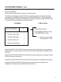
36
OUTPUT REPORTS
To simplify record keeping, the BT-000 is equipped to send the test results and other
information to a printer. The test results will automatically be sent to an attached,
compatible printer. To send the other information to the printer, push the -/DOWN ARROW
in the MAIN MENU screen until the third screen. Then, push the first “<” key to display the
following screen.
Output Reports screen
OUTPUT REPORTS
#
OUTPUT LAST TEST
<
OUTPUT SETTINGS
<
OUTPUT DATALOG
<
OUTPUT STATISTICS
<
Use the #/RETURN key to return to
the MAIN MENU screen.
a. Choose an option using the
appropriate “<” key.
Using the OUTPUT LAST TEST function sends the results of the last test to the printer.
Using the OUTPUT SETTINGS function sends the setup parameters of the last test to the
printer. When the BT-1000 has just been turned on, the default is the BURST test.
Using the OUTPUT DATALOG function will send the contents of the datalog to the printer.
Using the OUTPUT STATISTICS function will send the statistical calculations, the
Histogram, the X-Bar chart, and the R-Bar chart to the printer.
RS232-C PORT
The BT-1000 permits the transmission of datalog information to an external computer or
datalogging device that will accept an ASCII data stream. The RS232C, DB 25 connector
is located on the BT-1000 rear panel. The RS-232C configuration is NULL. It is important
that a serial RS232 cable ONLY be used for connecting to the external device. DO NOT
use a Null Modem Cable or Adapter. The output configuration of the data stream is shown
in Appendix “A”.
Only datalog information is transmitted to the external device. Settings and statistical
information inside the BT-1000 programs are not transmitted. Datalog information may then
be used in any program format the user chooses.
Datalog information is transmitted after every test. When collecting data the user must set
up the data receiving device to properly collect the data stream. Typical installations include
the use of MS Hyperterminal found on most Windows operating systems. Other
software may be utilized to convert the ASII datastream directly to “keystroke” format which
can be directly loaded into most spreadsheet formats. Contact TME for information on
compatible program software.
NOTE: The RS232C connection is for output data only. No input information for instrument
control can be accepted.
37
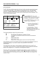
STATISTICS
STATISTICS MODE
The BT-1000 set in statistics display mode can calculate the basic statistics of a series of
tests stored in the datalog. The statistics calculate for valid test data only. T-Ovr and
“Reject” data are not calculated. The statistics display mode looks like this:
STATISTICAL DATA
COUNT
AVG
STD
:
:
:
7
10.00
0.50
TESTS
Psig
Psig
MAX
MIN
RANGE
:
:
:
12.00
7.00
5.00
Psig
Psig
Psig
AVG = mean of all the valid tests
STD = standard deviation of the tests
HISTOGRAM MODE
When set to the HISTOGRAM display mode, the BT-1000 calculates and displays a 5-bar
histogram with a range of ± 3σ . The HISTOGRAM screen looks like this:
HISTOGRAM
Cells
0.00
1.00
2.00
3.00
4.00
5.00
Ends
f%
10
20
50
20
0
--100
fc
1
2
5
2
0
--10
[Psig.]
#:
Legend
10
*
**
*****
**
Cells
f%
fc
W
#
:
:
:
:
:
interval boundaries
percentual frequency
frequency
interval width
number of valid tests
-------------------W: 1.00
Readings
#:
W:
10
1.00
=
=
There are 10 valid tests in the datalog.
The cell (interval) width is 1.00 Psig.
Cell #1
Cell #2
Cell #3
Cell #4
Cell #5
:
:
:
:
:
0.00
1.00
2.00
3.00
4.00
->
->
->
->
->
1.00
2.00
3.00
4.00
5.00
=
=
=
=
=
holds 10% (1 test) of the samples
holds 20% (2 tests) of the samples.
holds 50% (5 tests) of the samples.
holds 20% (2 tests) of the samples.
holds 0% (0 tests) of the samples.
38
STATISTICS Con’t.
CONTROL CHARTS MODE
When set to the X or R charts display, the BT-1000 calculates and displays a control chart
that is displayed like this:
_
_
X
#:
1
N:
2
[Psig.]
X
: Chart type
#
: Number of tests in next subgroup
U
*
*
12.40
N
: Subgroup size
_
*
*
*
*
U
: UCL (Upper Control Limit)
X
*
* *
*
*
*
6.20
L
: LCL (Lower Control Limit)
*
*
_
L
*
0.00
X
: Center Line
@ { 10:00a > 12:51p
}
* 6.20
Last subgroup point plotted
The limits for the control charts can be either manually entered and changed, or
automatically calculated. These operations are accessed from the Test Data Menu
(accessed from the + Up Arrow key) or thesecond Main Menu screen. Push the “<” key
across from the STATISTICS DATA option and the following screen is used to
display/modify the parameters. (CAUTION: Returning to the Main Menu may lose the
datalog if the OVERWRITE WARN key is set at NO).
STATS. SETTINGS
_
X
UCL:
0.0
X
LCL:
0.0
R
UCL:
0.0
R
LCL:
0.0
SIZE, N
0
/\
In H2O
In H2O
In H2O
In H2O
\/
#
<
<
Use the #/RETURN key to return
to the Main Menu.
TO CHANGE PARAMETERS
USE /\ or \/ THEN <
TO ENTER SELECTION
CALCULATE UCL & LCL
Use the ARROW UP/+ key or the
ARROW DOWN/- key to position
pointer alongside of the
parameter to change.
<
a. Use one of the top three “<” keys
to change a setup parameter.
b. Use the bottom “<” key to
calculate the upper and lower
control limits for X & R charts.
The following definitions apply to the previous screen:
X :
The average of the readings in a sample of N tests.
R :
The range of the difference between the minimum and maximum readings.
UCL:
Upper Control Limits.
LCL:
Lower Control Limits.
N :
Sample size (sub groups in a test run) – number of tests averaged to
determine one point on the charts. N must be set between 2 and 20.
The LCL or UCL can be entered or changed manually based on operator calculations,
or the BT-1000 can calculate them. The BT-1000 calculations are based only on the test
results stored in the datalog. Each point on the X and R chart is an average of the
number of tests in N.
39
ALARM, WARNING, PREFILL AND BLEED
To access any of these settings, press the third “<” key from the third page of MAIN MENU.
The following screen will be displayed:
MISC. SETTINGS
REJECT ALARM
/\
:
WARN OVERWRITE:
\/
#
At this point press the “<” key of the setting
to be changed.
ON/OFF
<
< Toggles alarm bell ON/OFF.
YES/NO
<
< Toggles Datalog erase warning YES/NO
PREFILL TIME (SEC):
0
<
< Set the prefill timer (optional)
BLEED TIME (SEC):
0
<
< Set the bleed timer (optional)
REJECT ALARM (AUDIBLE)
The Reject Alarm is designed to alert the operator when a failure has occurred. It is only
useful in the CREEP test and the LEAK TEST since they are the only tests that can detect
a reject.
WARN OVERWRITE
This WARNING alerts the operator when data will be lost due to changing tests or setup
parameters. Going out of a particular test mode signals to the instrument that a different
test is going to be run, or different parameters are going to be entered. In either case, the
statistics based on the Datalog are no longer applicable and a new set will be begun. This
will destroy any existing data. To prevent the loss of data if the same test is being
continued, a DATA WARNING is displayed to alert the operator to the impending data loss.
CAUTION: WE RECOMMEND THAT THE OVERWRITE WARNING BE SET TO “YES”
TO ALWAYS PROVIDE THE USER THE OPTION TO SAVE THE CURRENT DATALOG.
The Datalog Warning warns the operator that
DATA STORAGE OPTIONS
continuing the operation will destroy past test
FOR DATALOG & STATS
data.
The “#”/Return key will return the program to
• START NEW DATALOG
the MAIN MENU to save or print the datalog.
The “*”/START key continues into the test
+ ADD TO PREV. DATA
and erases the past datalog.
The “+”/UP ARROW key continues into the
# EXIT TO MAIN
test and adds the new data to the previous
data.
PREFILL (OPTIONAL)
When testing larger than normal packages the time it takes to fill the package can
sometimes be very long. To avoid an extended waiting period for each test, the BT-1000
can be equipped with a prefill function. The operator simply adjusts the amount of time
necessary to fill the package prior to pressurization.
BLEED (OPTIONAL)
When equipped with the optional bleed valve, the BT-1000 will exhaust the pressure inside
the part at the end of each test.
40
CALIBRATION MODE
Version 5
The BT-1000 provides a calibration menu which allows access to the pressure reading
calibration, factory-set flow rates, contrast & time adjustments. To reach the calibration
menu, press the fourth “<” key from the third page of the main menu. The instrument will
respond with the following screen:
SENSING RANGE CAL.
<
Pressure readings calibration
FLOW RATES CALIBR.
<
Flow number adjustments
ADJUST CONTRAST
<
LCD display contrast control
SET TIME & DATE
<
Time and date adjustment.
The last two items in the menu (“ADJUST CONTRAST” and “SET TIME & DATE”) can be
accessed/modified at any time without any special considerations.
The items “SENSING RANGE CAL.” and “FLOW RATES CAL.” require a different
procedure depending on what is to be done to the instrument:
IF THE BT-1000 CALIBRATION IS TO BE CHECKED:
Follow all the instructions and disregard references to adjustments and calibration.
Start from the section “SENSING RANGE CALIBRATION”.
IF THE BT-1000 IS TO BE CALIBRATED:
Warning:
Internal calibration should be performed only by qualified instrument and/or
metrology technicians familiar with electro-pneumatic instrumentation and equipped
with proper calibration equipment. REMOVAL OF THE INSTRUMENT COVER voids
the factory warranty. Calibration traceability becomes the responsibility of the
instrument owner when this procedure is followed.
REMOVE POWER FROM THE BT-1000 BY TURNING OFF THE POWER SWITCH THEN
UNPLUG THE POWER CORD.
WARNING
DANGEROUS POTENTIALS EXIST AT SEVERAL POINTS THROUGHOUT THIS
INSTRUMENT. WHEN THE INSTRUMENT IS OPERATED WITH THE COVER
REMOVED, DO NOT TOUCH EXPOSED CONNECTIONS OR COMPONENTS.
Remove the top cover from the instrument, locate the “JP4” jumper (in the small board
towards the back/left corner of the BT-1000), move the jumper to the “CALIB” position.
Then reconnect the power cord to the AC outlet and turn the instrument back ON.
41
CALIBRATION MODE, Cont.
Version 5a
SENSING RANGE CALIBRATION
This function is used to check/adjust the pressure calibration of the BT-1000. To access,
press the top “<” key, then a short reset sequence will follow ending in this display:
PRESSR. CALIBR. SETUP
These setup steps must be followed before actual
calibration of the instrument can begin.
1 : CONNECT STANDARD
TO FILLING PORT.
2 : OPEN SENSING PORT
TO ATMOSPHERE
Connect a pressure standard to the filling port (large OD
tubing).
PRESS * WHEN READY
Open the sensing line to Atmosphere (small OD tubing).
When the setup steps have been completed press the
“*” key. The “CAL. SENSOR OFFSET” will follow.
PRESSURE SENSOR OFFSET CALIBRATION
OFFSET: 52 DIGITS
If checking calibration, verify that the offset is within the
10-90 digits acceptable range.
If calibrating, set POT1 to read 50 digits.
:
This line shows the current offset.
SET PT1 FOR:
50 DIG.
(VALID: 10-90)
:
:
CAL. SENSOR OFFSET
…… PRESS ANY KEY …..
Target offset during calibration (50) use POT1
Acceptable range (10-90) if checking calibration
:
When done setting the offset, press any key.
The “CAL. SENSING RANGES” screen will follow.
PRESSURE SENSOR SPAN CALIBRATION
This function is used to check/adjust the different pressure ranges of the pressure
transducer in the BT-1000. The pressure range is calibrated in five segments (sub-ranges)
of the total span:
R1: 0.0-2.5
R3: 5.0-10 R5: 25-50
[Psig]
R2: 2.5-5.0 R4: 10-25 (Main span adjustment)
CAL. SENSING RANGES
READING: 0.00 PSIG
R1 [ 0-2.5 PSIG]
PT3
SPAN:
SPAN:
0.0
0.00
%FS
Psig
SET PRSR: + - <1&2
USE * TO SET OFFSET
USE <4 FOR UNITS
:
:
:
:
:
:
:
:
This line shows the current pressure reading.
R1 = Range#1 , [0-2.5 Psig] = Limits of Range 1
PT3 – Adjustment pot. For range#1 POT3.
Reading from the Span range in % of span.
Reading from the Span range pressure units.
Use the up/dn arrows to raise/lower pressure.
Use the “*” key to recheck the offset.
Use the <4 key to change the pressure units.
42
CALIBRATION MODE, Cont.
Version 5a
Calibration check procedure: Use the up/dn arrows to set the following pressures: 2.5,
5.0, 10.0, 25.0, and 50.0 Psig. Verify that the readings of the BT-1000 are within ± 0.5% of
10 psig below 10 psig, or ± 0.5% of 50 psig above 10 psig of the readings from Pressure
standard being used. If adjustments are needed refer to the next section; otherwise, press
“#” to return to the CALIBRATION MENU.
CALIBRATION PROCEDURE:
Ranges 1, 2, 3 and 4 can be adjusted independently. Range 5 is the master range that
adjusts the span of the transducer. Changes to range 5 (POT#0) will affect all the other
ranges; therefore it must be calibrated first.
Use the up/dn arrows to set the following pressures, always pressing “*” to verify that the
offset is still in range:
Set
Set
Set
Set
Set
50.0 Psig
2.0 Psig
4.5 Psig
9.5 Psig
24.0 Psig
(Range5) and adjust POT0 until reading = 50.0 Psig,
(Range1) and adjust POT3 until reading = 2.0 Psig,
(Range2) and adjust POT4 until reading = 4.5 Psig,
(Range3) and adjust POT5 until reading = 9.5 Psig,
(Range4) and adjust POT6 until reading = 24.0 Psig,
check offset.
check offset.
check offset.
check offset.
check offset.
This completes the pressure sensor calibration. Proceed to the flow calibration section to
complete calibration.
CHECKING FACTORY SETTINGS FOR OUTPUT FLOW *
This function is used to check/adjust the factory setting flow rates assigned to the flow
numbers used in the BT-1000. To access, press the second “<” key from the calibration
menu, then a short reset sequence will follow ending in this display:
These setup steps must be followed before actual flow check of the instrument can begin:
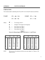
FLOW RATE CALIBR.
1:
2:
CONNECT STANDARD
TO FILLING PORT.
OPEN SENSING PORT
TO ATMOSPHERE
Connect a Flow Standard to the filling port (large OD
tubing).
Open the sensing line to Atmosphere (small OD
tubing).
When setup has been completed, press the “*” key.
PRESS * WHEN READY
* Note that there is no flow transducer in the instrument. The BT-1000 only measures pressure
or pressure changes with its internal pressure transducer in the four test modes. Flow settings
are for instrument reproducibility only.
43
CALIBRATION MODE, Cont.
Version 5a
FACTORY FLOW CHECK (Cont.)
The flow rates are checked/adjusted in two groups:
Low flows ± 3 scfh, @ 10 Psig
------------------------------------------------------------------#1:
5 scfh (2.3 slmp)
#5:
25 scfh (12 slmp)
#2:
10 scfh (4.7 slmp) #6:
30 scfh (14 slmp)
#3:
15 scfh (7.0 slmp) #7:
35 scfh (16 slmp)
#4:
20 scfh (9.3 slmp) #8:
40 scfh (19 slmp)
------------------------------------------------------------------FLOW
+
- :
* :
# :
RATES
High flows ± 5 slmp, @ 7.5 Psig
----------------------------------------------#9:
20 slmp
#13: 40 slmp
#10: 25 slmp
#14: 45 slmp
#11: 30 slmp
#15: 60 slmp
#12: 35 slmp
#16: 65 slmp
-----------------------------------------------
CALIB.
SET FLOW RATE
NEXT FLOW #
EXIT CALIB.
:
:
Use up/dn keys to adjust the flow rate.
Use “*” to go to the next flow number.
PRESSR:
10.00
:
Test pressure being used (automatically set).
FLOW # :
9
:
Flow number being checked/adjusted.
Psig
AIRTIGHT
When this procedure begins, the BT-1000 sets the pressure to 10.0 psig and the flow to #1.
Use a flow gauge to measure the flow rate coming out of the filling line and compare it to
the table shown above.
If any adjustments are needed use the up/dn keys until the desired flow rate is achieved.
Then press the “*” key to go to the next flow number. When the BT-1000 sets a low flow
number (1-8), it will first open the flow to its maximum value (≅ 70 slmp), therefore a flow
gauge capable of handling 70 slmp is recommended. A bypass can be set up to divert the
excess flow when changing flow numbers.
The BT-1000 will automatically set the correct pressure to check/adjust the current flow
number. The instrument will cycle through flow number 1-16 then back to 1 by pressing the
“*” repeatedly.
When all the adjustments have been completed press the “#” key to exit.
NOTE:
When pressure calibration is completed, GMP procedures require that a next calibration
label be applied to the instrument. It is preferable to apply the label over one cover fastener
to prevent changes without label removal.
REMOVE POWER FROM THE BT-1000 BY TURNING OFF THE POWER SWITCH AND
UNPLUG THE POWER CORD.
Replace the calibration lock jumper “JP4” back in the “LOCK” position, then put the cover
back on the instrument, reconnect the power cord and turn the instrument back ON. This
completes the calibration and flow check procedure of the BT-1000.
44
CALIBRATION MODE, Cont.
Version 5a
SET TIME AND DATE
This procedure is used to change or correct the time and date. Under normal operation
neither the time nor the date will need to be changed. However, the BT-1000 is set for
eastern time, so if it is used in a different time zone the time will need to be corrected.
Pressing the fourth “<” key in the CALIBRATION MODE menu displays the following
screen:
SET TIME & DATE
HOURS
AM / PM
MINUTES
DATE
MONTH
YEAR
PICK
USE
:
:
:
:
:
:
8
0
0
1
1
93
/\
\/
Use the +/ARROW UP key or the
-/ARROW DOWN key to position
pointer alongside of the item to
change.
#
[1 - 12] <
[0 = AM]
[0 - 59]
[1 - 31]
[1 - 12]
[ 93 + ]
Use the #/RETURN Key to return to
the Main Menu.
a.
ITEM WITH /\ & \/
< 1 & 2 TO CHANGE
{
ENTER
8:00
NEW
AM 1/1/01 }
TIME / DATE
b.
<
c.
Use the top ‘<’ key to
increase the item.
Use the second “<” key to
decrease the item.
Use the fourth “<” key to
set the changes.
After all the changes are made, the fourth “<” key must be pressed to accept all the
changes and set the clock and calendar. If the fourth “<” key is not pressed, no changes will
be made, and all items will return to their previous settings.
SET CONTRAST
DISPLAY
USE
CONTRAST
/\
USE # *
#
\/ TO CHANGE #
TO
EXIT
Use the RETURN/# key to return to the
READY screen.
Use the UP ARROW/+ to increase the
contrast.
Use the DOWN ARROW/- to decrease
the contrast.
The range of adjustment is between
75 and 125.
NOTE: The LCD contrast is affected by cold temperatures. It is recommended that
the instrument warm up for one half hour prior to making adjustments.
45
F.A.Q.’s
Q:
A:
How do I use PREFILL and BLEED?
If your instrument is not equipped with the PREFILL or BLEED options, set them to
zero by repeatedly pressing their function key. After the count of ten, they will reset
to zero. If you do have either of these options installed, refer to the
MISCELLANEOUS CONTROL section of this manual.
Q:
A:
How do I change the test units?
In any test the units can be changed from the change pressure screen by pressing
the second “<” key.
Q:
When trying to creep test a porous package, the BT-1000 displayed this screen:
UNABLE TO SET PRESSURE
a)
burst occurred
b)
low line pressure
c)
insufficient flow
What is wrong?
The instrument tried to set the required pressure through the specified flow setting
and was unsuccessful. This can be caused because the selected flow setting was
too low, the part might have burst or popped off the fixture, or in some cases the line
pressure might not have enough flow capability.
A:
Q:
A:
How can I get a printout of a test curve?
Select the “TEST PLOT” display mode, then press “+” to get the print menu, select
OUTPUT REPORTS, then pick LAST TEST.
Q:
A:
When I try to store or recall program #0 the BT-1000 just beeps.
Valid program numbers are #1 through #10 for each test mode.
Q:
A:
The BT-1000 display garbled data and behaves erratically. How can I reset it?
The BT stores test parameters, results and other settings in permanent memory.
Sometimes due to power surges, electrostatic discharges or heavy interference the
permanent memory can become garbled. To reset it, follow this sequence:
a)
Turn the instrument OFF
b)
Press and hold the top “<” key
c)
Turn power back ON
d)
Release the top “<” key.
The BT will reset all memories and devices.
Q:
When I turned the BT-1000 on these messages appeared:
RESET:
ZERO PRESSURE
RESET:
ZERO FLOW
RESET:
COMPLETE
Then it started normally.
A:
The BT was performing a total reset that clears all pneumatics and electronics (see
previous question).
46
APPENDIX A
:
RS232
BT-1000-V5 RS-232C PORT CONFIGURATION
COMM CONFIGURATION
----------------------------------BAUD RATE
:
1200
WORD SIZE
:
7 BITS
STOP BITS
:
1 BITS
PARITY
:
EVEN
HARDWARE CONFIGURATION (NULL MODEM)
-----------------------------------------------------------------GND
:
pin 1, 7
Txd
:
pin 3
Rxd
:
pin 2
RTS
CTS
:
:
(pin 4)
(pin 5)
RTS & CTS ARE
TIED TOGETHER
INTERNALLY
DTR
DSR
DCD
:
:
:
(pin 20)
(pin 6)
(pin 8)
DTR, DSR & DCD
TIED TOGETHER
INTERNALLY
BT-1000 RS232 PORT DATA STREAM
FIELD
-------PART NUMBER
LENGTH
-----------5 BYTES
EXAMPLE /
DESCRIPTION
-----------------------------------------------“00123”
TEST NUMBER = 123
PRESSURE DATA
5 BYTES
“123.4”
MEASUREMENT 123.4
ELAPSED TIME
5 BYTES
“100.0”
TIME - 100%
RESULT CODE
1 BYTE
“0”
0 = BAD TEST
1 = TIME OVER
2 = BURST
3 = ACCEPT
4 = REJECT
UNITS CODE
1 BYTE
“0”
0 = Psig
1 = In H2O
TEST MODE
1 BYTE
“0”
0 = BURST
1 = CREEP
2 = C-T-F
3 = LEAK
TEST TIME
6 BYTES
“1234am”
HHMMam - 12:34 am
TEST DATE
6 BYTES
“070494”
MMDDYY - 07/04/94
END OF LINE
1 BYTE
ASCII #13
“CR”
END OF TRANS:
1 BYTE
ASCII #10
“LF”
47
APPENDIX B
:
STATISTICS REFERENCE
FORMULAS USED
The formulas used for calculating the LCL and UCL for the X and R charts are as follows:
_
X CHART:
UCL =
X + A2 * R
R CHART:
LCL = X − A2 * R
Where:
UCL = D 4 * R
LCL = D3 * R
X
=
The average of ALL X
R
=
Averages of the ranges of all subgroups
A2
D3
D4
=
=
=
Factor taken from Table 1
Factor taken from Table 1
Factor taken from Table 1
TABLE 1
Factors for Determining the 3σ Control Limits in X and R Charts
N
2
3
4
5
6
7
8
9
10
NOTE:
A2
D3
D4
N
A2
D3
D4
1.880
1.023
.729
.577
.483
.419
.373
.337
.308
0.0
0.0
0.0
0.0
0.0
0.08
0.14
0.18
0.22
3.27
2.57
2.28
2.11
2.00
1.92
1.86
1.82
1.78
11
12
13
14
15
16
17
18
19
20
.285
.266
.249
.235
.223
.212
.203
.196
.187
.180
0.26
0.28
0.31
0.33
0.35
0.36
0.38
0.39
0.40
0.41
1.74
1.72
1.69
1.67
1.65
1.64
1.62
1.61
1.60
1.59
The accuracy of the statistics routines is two minor digits (1 In. Water or 0.04
Psig) max error.
48
APPENDIX C:
USING THE PACKAGE PORT
AND CLOSED PACKAGE PROBE
For the most consistent results in applying the BT-1000 pneumatic and sensing system to
the package test, TM Electronics invented and patented the Package Port. This device
seals the pneumatic path from the instrument to the inside of the package under test.
The Package Port is a simple device which seals its flexible inner diameter to the taper
lock, outer diameter of the instrument Closed Package Probe Assembly. The flanged
surface of the Package Port has a double sided adhesive disk applied for each test. The
adhesive disk is then fastened to the package surface. The thin adhesive couples the
package and Package Port.
The Closed Package Probe is an assembly of an air supply tube and a sensing tube which
have separate couplings to the BT-1000 instrument. It is important to provide the sensing
tube with an unobstructed path inside the package. This usually requires that after
penetration of the package surface with the cutting diameter of the Probe as it enters the
Package Port that the package be rotated 90-180 degrees from the initial penetration
position. The symptom of a blocked sensing tube is a high level of pressure after a Burst
test is complete, or variations in pressure during a Creep test. These symptoms result from
the cut flap of material blocking the sensing tube.
The steps for using the Closed Package Probe and Package Port are:
1. From the roll of Package Port adhesive, peel off the top release paper.
2. With a Package Port in hand, firmly press the flange on the adhesive.
3. Gently roll the flange away from the adhesive roll, thus leaving the adhesive
attached to the Package Port flange.
4. Press the port on the package. Locate the Package Port approximately in the
center of the package under test.
5. Place the Package Port and attached package under the Closed Package Probe.
Push the Probe cutting surface into the Package Port and into the package
through its outer material layer. Insure that the Probe tip is completely through
the material and the top of the Probe needle angle is in the package.
6. Rotate the Package Port and attached package 90 to 180 degrees from the entry
position to clear the Probe sensing tube.
7. Check to be sure that you did not puncture the opposite side of the package material
with the Probe cutting tip.
8. Activate the BT-1000 test cycle.
When the test is complete:
Remove the package and Package Port from the probe.
Remove the Package Port from the package.
Check the flange of the Package Port to be sure that the adhesive stayed on the
package. If it is attached to the flange, then peel it off. Do not apply multiple layers of
adhesive to the Package Port
Package Ports are reusable unless cracked or torn.
49
APPENDIX C
:
USING THE PACKAGE PORT AND PROBE (Cont.)
1. Install Package Port on packages
2. Insert probe tip into port and package.
When loading package onto the Closed Package
Probe, rotate the package 90 to 180 degrees
after the needle pierces the package
surface.
50
BT-1000 SPECIFICATIONS
DIMENSIONS
13”W x 15”D x 6 1/2 “ W
POWER
115V, 60 Hz, 150 Watt
CONTROLS
Electronic Pressure Control
Electronic Flow Control
Push Buttons, Keylock, Power ON/OFF Switch, Key
Pad.
SINGLE TESTS AVAILABLE
Leak, Burst, Creep, Creep to Failure
DUAL TESTS AVAILABLE
Creep/Leak, Creep/Burst, Leak/Burst, Leak/Creep to
Failure
DISPLAY
LCD 20 Character x 16 Line Alphanumeric/Graphic
Display
DISPLAY UNITS
Inches of H2O, PSIG (other units optional)
DATALOG MEMORY
Saves up to 1000 test results
PROGRAM MEMORY
Saves up to 80 test programs (ten per mode)
STATISTICS
X-bar Chart, R Chart, Histograms
PRINTER OUTPUT
80 Character, Epson compatible
COMPUTER OUTPUT
RS-232 output of test results and datalog
PRESSURE SETTING RANGE
0.36 PSIG (10 In. H2O) to 50 PSIG (1384 In. H2O)
PRESSURE SETTING ACCURACY 2 In. H2O
READING ACCURACY
± 0.5% of 10 PSIG below 10 PSIG
± 0.5% of 50 PSIG above 10 PSIG **
READING RESOLUTION
.5 In. H2O / 0.02 PSIG
**Revised 4/29/02
51
BT-1000-V5
WARRANTY
TM Electronics, Inc. warrants to the original use purchaser that it will repair or replace, at its
option, any product under normal use and service that proves defective in material or
workmanship, as determined by TM Electronics’ inspection, within one year from the date
of purchase when promptly returned to the TM Electronics factory. This warranty does not
extend to damage caused by dirty air, water or water vapor, oil or oil vapor intrusion
from the air supply source or from the product tested.
If TM Electronics’ inspection discloses no defect in material or workmanship, repair or
replacement will be made at customary charges. Freight charges are the customer’s
responsibility.
The foregoing warranty supersedes, voids and is in lieu of all or any other warranties,
expressed or implied, and no warranty of merchantability or fitness for particular purposes
is intended or made. TM Electronics’ sole obligation and the original use purchaser’s sole
remedy is as stated above and in no event shall TM Electronics be liable for any special,
direct, indirect, incidental, consequential or other damages or expenses of any nature
including, without limitations, loss of profits of production time incurred by the original use
purchaser or any other party.
TM Electronics, Inc.
BT-1000-V5 Operator’s Manual
2001 TM Electronics, Inc.
Rev. 10/01
52