1
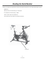
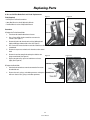
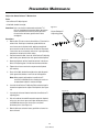
Schwinn® IC Bikes
IC Elite, IC Pro, IC Evolution, IC Evolution SR
Service Manual
PN001-7145 (08/2007)
Table of Contents
Important Safety Warnings - - - - - - - - - - - - - - - - - - - - - - - - - - - - - - - - - - - - - - - - - - - - - - -4
Recommended Tools and Lubes- - - - - - - - - - - - - - - - - - - - - - - - - - - - - - - - - - - - - - - - - - - -5
Reading the Serial Number - - - - - - - - - - - - - - - - - - - - - - - - - - - - - - - - - - - - - - - - - - - - - - -6
Basic Troubleshooting - - - - - - - - - - - - - - - - - - - - - - - - - - - - - - - - - - - - - - - - - - - - - - - - - -7
Replacement Part Instructions - - - - - - - - - - - - - - - - - - - - - - - - - - - - - - - - - - - - - - - - - - - 11
Preventative Maintenance - - - - - - - - - - - - - - - - - - - - - - - - - - - - - - - - - - - - - - - - - - - - - - 12
Important Contact Numbers - - - - - - - - - - - - - - - - - - - - - - - - - - - - - - - - - - - - - - - - - - - - - 14
3
Service Manual
Important Safety Warnings
This icon means a potentially hazardous situation which, if not avoided, could result in death or serious injury.
Failure to follow these precautions can cause damage to the Schwinn® IC Bike series, serious injury to users and
bystanders, and can also compromise the effectiveness of your exercise program.
Before using this equipment, obey the following warnings:
Read and understand the complete Owner’s Manual.
Read and understand all Warnings on this machine.
1. Keep children away from this machine and / or supervise them closely if they are near the machine or present during its operation.
This machine is not suitable as a children’s toy. There is a natural tendency for children to want to play on exercise equipment and
parents and other in charge of children should be aware of their respective responsibilities. Moving parts that may appear to present
obvious hazards to adults may not appear to do so to children.
2. Consult a physician prior to commencing an exercise program. If, at any time, you feel faint or dizzy, or experience pain, stop and
consult your physician.
3. Inspect this machine for loose parts or signs of wear. Pay special attention to the Seat, Pedals, and Crank Arms. Do not use if found in
this condition; contact Schwinn Customer Service.
4. Set up and operate this exercise machine on a solid level surface.
5. This machine contains moving parts. Use Caution. Do not wear loose clothing or jewelry.
6. This machine is designed for a User’s Weight Limit of 300 pounds (136) kilograms. Do not use if you are over this weight.
7.
Set up the machine so that there is a free area of 19.7 inches ( 0.5 m) on all sides of the machine. Keep third parties out of this
area when the machine is in use.
8. Operate the machine in the manner described in this manual. It can be hazardous to over-exert yourself during exercise
9. Make sure that all positional adjustment devices are securely engaged.
4
Service Manual
Recommended Tools and Lubes
®
We recommend the following tools and lubes to properly assemble, maintain and repair all Schwinn
Indoor Cycling bikes.
Lubes
Tools
®
1. Torque wrench w/ 8mm Allen Key socket: used to tighten the 1. Schwinn Fit-Tech Silicone Spray: recommended for the
brake pads and all moving parts (e.g., handle bar post, seat
crank bolts of crank arms to 480 lbf/in.
post & slide, pop-pins, resistance knob etc.)
2. Pedal wrench: Has 15mm and 9/16” wrench to tighten and loosen
2. Schwinn® Equipment Polish: recommended on a damp cloth
pedals.
when wiping down the frame after use.
3. Crank puller: needed to take o right and left crank arms.
3. Schwinn® Citrus Chain Wax: recommend to lubricate
the chain through the rear hole in the chain guard as the
4. ISIS Insert Plug for Crank Puller, M12 x 1.0
flywheel is rotating.
5. Bottom bracket tool for ISIS Overdrive BB. used to take out bottom
4. Schwinn® Quick Shot: recommended for the threads of
bracket from frame.
stabilizer bolts and pedals before tightening to crank arms.
6. Adjustable wrench: used to tighten or loosen the pop pin
assembly from frame.
7. 17mm wrench: used to adjust the inside axle nuts closest to the
flywheel bearings.
8. 15mm wrench: used to loosen the outside axle nut on each side
of the flywheel bearings.
9. 14mm wrench: used to tighten the nuts of the seat bracket.
10. 13mm wrench: needed during assembly for the front and back
stabilizers nuts and bolts.
11. 11mm wrench: used to tighten the larger bolt of the brake
assembly.
12. 10mm wrench: used to adjust chain tensioner bolts during chain
tightening, transport wheel nut and bolt and front nut of the
resistance assembly when centering brake pads.
13. 8mm wrench: goes to the smaller resistance knob nylon nut
(older models) and smaller brake assembly bolt.
14. 7mm wrench: used to loosen guide rod nut when replacing
guide rod springs.
15. 5mm Allen wrench: used to tighten the bolts on Evolution
stabilizers.
16. Phillips Head screwdriver: used to loosen the screw in the
brake pads and the chain guard screws (newer models).
17. 3mm Allen wrench: used for the screws of the water bottle
cages.
18. Smart Release™ adjusting tool: high quality tool specifically
designed for use with the new adjustable Smart Release™
mechanism. (SR Models only).
5
Service Manual
Reading the Serial Number
Find the serial number on the underside of the machine base. Decode the information in the serial number with the below instructions:
AAABCCCCCC
AAA= Day of the year manufactured (e.g., 35 = February 4th)
B= Last digit of year manufactured (e.g., 6 = 2006)
CCCCCC = Unique code for each individual unit.
Serial number tags on newer models also read date of manufacture.
Serial Number
6
Service Manual
Basic Troubleshooting
Problem: Loud Squealing Sound From the Brake
FFigure
Fi
ig
igu
gu
urre
e1
Solution:
A. Use a Phillips Head screwdriver to remove the bolt and spring from
the brake assembly. (See Figure 1.)
B. Slide the brake pads out of the assembly.
C. Rough up the surface with a wire brush if the pads look
glossy.
D. Saturate the brake pads with silicone lubricant after they
have been roughed up.
E.
Replace the brake pads.
F.
Tighten the bolt and spring to the pads only finger-tight. This
gives the brake pads a longer life.
Figure 2
Problem: Brake Pads are too Tight on Minimum Resistance
Solution: Turn the resistance knob all the way to the right
(maximum resistance) and let it sit for two hours. This
compresses the guide rod springs allowing space
between the pads and the flywheel. (See Figure 2.)
7
Service Manual
Basic Troubleshooting
Problem: Brake Pads Off Center
Figure 3
Solution:
A. Use a 10mm wrench to loosen the nylon nut on the front of the
bike.
B. Adjust the brake assembly until the brake pads are evenly
spaced from the flywheel.
C. Tighten the nylon nut using moderate torque.
Figure 4
Problem: Chain is too Loose
Solution:
A. Use a 15mm wrench or socket to loosen each axle nut of the
flywheel.
B. Use a 10mm wrench and turn each chain tensioner bolt 1/4
turn to the right.
C. Get on the bike and check for any play in the chain by
rocking back and forth on the pedals.
D. Tighten the axle nuts on the flywheel once the pedals and
the flywheel are moving as one.
NOTE: Make sure that the flywheel aligns with the frame.
8
Service Manual
Basic Troubleshooting
Problem: Chain Makes a Grinding Sound
Solution: Chain too tight and/or the flywheel out of alignment.
A. Use a 15mm wrench to loosen each axle nut.
B. Adjust the 10mm chain tensioner bolts to align the flywheel
with the frame. Make sure that the chain tensionis adjusted
properly without being too tight.
C. Adjust the chain tension by locating the point where the
chain is tightest during one revolution of the crank.
D. Check the tension. You should be able to move the chain up
and down about 3/8” (in either direction).
E. Lubricate the chain.
F.
Take the bike for a test ride.
Figure 5
Problem: Bike is Wobbling or Uneven While Riding
Solution:
A. Check the foot levelers on the bottom of the stabilizers.
B. Adjust the levelers and the bike until it is square on the floor.
C. Secure the leveler nuts to prevent them from loosening.
(See Figure 5.)
9
Service Manual
Basic Troubleshooting
Problem: Crank Arms or Pedals Feel Loose
Figure 6
Solution:
A. Make sure the pedals are tightly screwed into the crank arms.
(See Figure 6.)
B. Make sure the crank bolts on both crank arms are tight.
C.
Make sure the square opening in the crank arms have not been
rounded out. This problem is caused when the bike has been
ridden with loose arms. Replace the crank arm if the sqare taper
shows damage.
D. Make sure the bottom bracket is tight in the frame and bearings
operate smoothly.
Problem: Handlebar or Seat Post is too Tight
Solution:
A. Clean and lubricate the handlebar/seat post extension tube
and frame sleeves with silicone lube.
B. If fit remains tight, switch the handlebar or seat post with
one from another bike.
C. If this does not fix the problem order a new sleeve.
10
Service Manual
Replacing Parts
IC Pro and IC Elite Brake Rod and Knob Replacement
Tools Required:
Figure 7
Figure 8
Figure 9
Figure 10
• #2 Phillips or Flat Head Screwdriver
• 10mm Box Wrench or Small Adjustable Wrench
• 7mm Box Wrench or Small Adjustable Wrench
Procedure:
A. Replace the Tension Control Knob
1.
Turn the tension control knob to least resistance.
2.
Use a flat or phillips head screwdriver to remove the
shrouds. (See Figure 7.)
3.
Remove the brake rods from the rod carrier by holding the rod
tightly and lifting up and out of the carrier. (See Figure 8.)
4.
Use a wrench to remove the 10mm nut on the end of the tension
control knob.
5.
Remove the square nut and rod carrier from the tension control
knob.
6.
Remove the tension control knob and replace with the new
longer control knob. (See Figure 9.)
7.
Replace the rod carrier, square nut and 10mm nut. Secure
tightly. (See Figure 10.)
B. Replace the Brake Rods
1.
Invert the brake rod and use a wrench to remove the 7mm nut on
the end of the rod.
2.
Remove the rods, springs, and rubber grommets and replace
with new shorter rods, springs and rubber grommets.
11
Service Manual
Preventative Maintenance
Attention: Any Schwinn® bike that is allowed to operate with torque in excess of the specified values does not qualify for warranty
replacement for the crank arms.
Do NOT torque crank bolts in excess of 360 obf/in. on IC Pro and IC Elite or 420 lbf/in on Evolution models. Overtightening causees
damage to the crank or the bottom bracket interface.
Daily Maintenance
At the end of each workout:
•
Release the brake resistance so that the brake pads do not contact the flywheel.
•
Clean the bike with Schwinn® equipment polish and a clean damp cloth.
•
Remove the handlebars from the head tube to allow the handlebar tube and sleeve to dry.
•
Release the brake resistance so that the brake pads do not contact the flywheel.
Weekly Maintenance
Inspect the Schwinn® Indoor Cycling bike for lose parts, nuts, bolts, etc. Pay special attention to the brake assembly, seat and
handlebar pop-pins. This will prolong the service life of the product.
Monthly Maintenance
•
Check the chain for proper adjustment.
•
Move the crank arms back and forth. If there is more than 1/4” movement in the chain before the flywheel turns, tighten the
chain (See page 9).
NOTE: Make sure you adjust both sides equally so that the flywheel remains in alignmentwith the frame.
•
Check the crank bolts with a torque wrench. The torque should not exceed 360 lbf/in for IC PRO and IC ELITE and 420 lbf/in for
the EVOLUTION models.
•
Check that both pedals are secured and properly attached to the crank arms.
NOTE: Only trained personnel should change the pedals. Unqualified people performing this procedure can cause threads to
cross. Crossed threads do not qualify for warranty replacement.
•
Make sure handlebar and seat pop-pins are fully tightened and operating smoothly.
Use extreme care when servicing the Schwinn® Indoor cycling bike with the chain guard removed. If your fingers or other parts of
the the body come into contact with moving parts inside the bike, amputation or other serious injury may occur. Before starting any
maintenance on the chain drive, familiarlize yourself with all moving parts. Never leave a Schwinn® bike unattended with the chain
guard removed.
12
Service Manual
Preventative Maintenance
Adjust the Smart Release™ Mechanism
Tools:
• Smart Release™ Adjusting tool
• 45 to 50 lb. dumbell or weight
Figure 11
Attention: Only a mechanic trained to work on Schwinn® IC
bicycles should do this procedure. Make adjustments
to the Smart Release™ mechanism only to restore
the mechanism to factory specifications. Never
overtighten.
Smart Release™
Adjusting Plate
Procedure:
1.
Ride the bike. This forces the the Smart Release™ mechanism
to break free. Pedal up to a moderate speed with little or
no resistance on the flywheel while applying enough back
pressure to the cranks to release the mechanism. Repeat this
several times to ensure that the mechanism is up to operating
temperature and to feel the initial setting.
2.
From the front of the bike, insert the Smart Release™ adjusting
tool into the space between the chain guard and the flywheel.
3.
Rotate the flywheel until the 7mm diameter hole in the Smart
Release™ adjusting plate is visible from the front of the bike.
4.
Tighten the resistance mechanism to prevent the flywheel
from rotating.
5.
Place a 45 or 50 lb. dumbell or weight on the right side pedal
(chain guard side) with the crank in the 9 o’clock position.
Figure 12
Note: When properly adjusted, the Smart Release™
mechanism should break free allowing the crank arm
to rotate down under this amount of weight.
6.
Insert the Smart Release™ Adjusting Tool so that the bend in
the tool corresponds to the shape of the flywheel. (See Figure
12.)
7.
Insert the pin of the tool into the hole of the Smart Release™
adjusting plate.
8.
Pull the handle of the tool UP toward the top of the flywheel
to increase the release pressure (higher breakaway force)
and DOWN to decrease the release pressure (lower
breakaway force). (See Figure 13.)
9.
Ride the bike to test that the factory specified resistance has
been achieved.
Figure 13
13
Service Manual