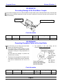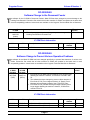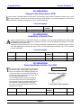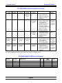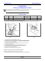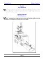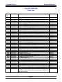
1
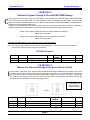
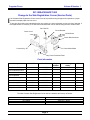
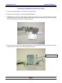
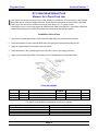
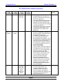
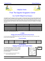
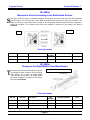
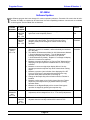
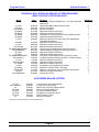
Copystar
Focus
April 2000
Volume 8 Number 1
W
elcome to the April 2000 Edition of the
Copystar Focus. With the beginning of the
new Millennium, Mita Copystar America Inc.,
which is responsible for marketing Copystar Copiers
and Mita Printers in North and South America, has
changed its name to Kyocera Mita America, Inc. as
of January 18, 2000.
Under Kyocera’s ownership, there will be an
integration of technologies and resources between
the companies. This will provide the Kyocera Mita
Corporation
with
enhanced
research
and
development, state-of-the-art printer controllers, new
network technology and a shortened development
period for new products. The result will be High
Efficiency Digital Copiers and Laser Printers that are
more innovative and competitive from a feature and
price standpoint.
Introduced in the second half of 1999, were the
RC-1800df, RC-2310 and RC-3010. Each machine
has the capability to accept universal options such
as a 7 Bin Mail Box (M-2007), SRDF-1 Document
Feeder and Facsimile functions.
The DP-1400/1800 B/W compact Laser Printers are
just a sample of the technology that will be
incorporated into future Copystar Products. The
addition of the Ci 1100 Full Color Laser Printer will
enhance our Color line with unique features as well
as compact design.
MODEL
CONTENTS
PAGE
CC-50/CS-2112/2013
Change to the Paper Feed Clutch
2
CC-50/CS-2112/2013
Software Program Change to Prevent EEP-ROM Damage
2
CS-2014/2114
Software Program Change to Prevent EEP-ROM Damage
3
CS-2014/2114
Measure to Prevent Damage to the Drum
3
RC-1500d/1500df/ST-500
Change to the Side Registration Cursor (Service Parts)
RC-1500d/1500df/2000d/ST-500
Measure for Paper Feed Jam
RC-1500d
Software Updates
7
RC-1500df
Software Updates
7, 8, 9, 10
Vi 85
Software Program Change
10
LDC-790
Software Program Change
10
All
Helpful Hints From the Copystar Diagnostic Center
RC-2000d
Measure to Prevent Jamming in the Switchback Section
13
Rc-2000d
Change to the Right Middle Cover/Eject Hooks
13
RC-2000d
Software Changes
RC-2000d
Change to the Motor Driver PCB
15
RC-2250/ST-8
Preventing Damage to the Deck Motor Coupler
16
RC-2250/2465
Preventing Premature Failure of the Heat Roller
16
RC-2250/2465
Software Change to the Document Feeder
17
RC-2250/2465
Software Change to Prevent Various Operation Problems
17
RC-4000d/5000d
Change to the Power Source PCB
18
RC-4000d/5000d
Availability of Special Tools
18
RC-4000d/5000d
Preventing Duplex Section Jam (J40)
18
RC-4000d/5000d
Software Updates
RC-4000d/5000d
ISU Ass’y Availability (Service Parts)
21
Fiery Si
Fiery Si Y2K Compliance
22
Fiery ZX
Fiery ZX 2100/3300 Parts Breakdown
4, 5
6
11, 12
14, 15
19, 20
22, 23
Copystar Focus
Volume 8 Number 1
CC-50/CS-2112/2013
Change to the Paper Feed Clutch
O
ver time, the Paper Feed Clutch may fail to function causing a PF/J-01 jam detection error. To prevent this
problem, the tension of the Spring that controls the Clutch Plate will be increased. A red marking placed on
the front side can identify the new Clutch as illustrated.
Old P/N
New P/N
Description
33306011
33306012
Paper Feed Clutch
Qty.
Old/New
1/1
Interchangeability
Price
Y/Y
$
CC-50/CS-2112/2013
Software Program Change to Prevent EEP-ROM Damage
C
ertain machine functions can cause a communication conflict between the Main EP-ROM and the EEP-ROM
(P/N 33227030) on the Main PCB. The communication conflict can damage the EEP-ROM. To prevent this
problem, the Main IC ROM software has been updated. If the problem occurs, both the Main IC ROM and EEPROM must be replaced at the same time.
EP-ROM Information
Old P/N
New P/N
Description
C/S
63827046
65827024
33327014
63827047
65827025
33327015
IC-ROM-NS15 (CC-50)
IC ROM-NS15 (CS-2112)
IC ROM (CS-2013)
7404
7135
58D3
Qty.
Old/New
1/1
1/1
1/1
Interchangeability
Price
Y/Y
Y/Y
Y/Y
$
$
$
The EP-ROM Data can also be downloaded from the Copystar Technical Web Site on Dealernet.
Page 2
Copystar Focus
Volume 8 Number 1
CS-2014/2114
Software Program Change to Prevent EEP-ROM Damage
C
ertain machine functions can cause a communication conflict between the Main EP-ROM and the EEP-ROM
(P/N 33227030) on the Main PCB. The communication conflict can damage the EEP-ROM. To prevent this
problem, the Main IC ROM software has been updated. If the problem occurs, both the Main IC ROM and EEPROM must be replaced at the same time.
Secondly, a high temperature offset problem may occur in the field after the main switch is turned on. Simulation
48 (Setting the fixing unit stabilization time) has been added to prevent this problem from occurring.
* Mode 1 (Exp 1 lights): Stabilization time in normal temperature conditions
Default is 29 (seconds).
* Mode 2 (Exp 2 lights): Stabilization time in low temperature conditions
Default is 100 (seconds).
Increasing the stabilization time can reduce the degree of the fixing offset.
Note: The setting range is between 18 and 120 for both modes above. The mode can be selected with the
exposure key. One increment is equal to one second.
EP-ROM Information
Old P/N
New P/N
Description
C/S
1AB27131
19527013
1AB27133
19527015
IC ROM Control (CS-2114)
IC ROM (CS-2014)
E842
D1D2
Qty.
Old/New
1/1
1/1
Interchangeability
Price
Y/Y
Y/Y
$
$
CS-2014/2114
Measure to Prevent Damage to the Drum (Service Parts)
I
n some cases, if the Drum Unit is twisted counterclockwise when being installed into the machine, it may come
in contact with the Main Charger Grid resulting in damage to the Drum. To prevent the chance that this can
occur, the shape of the Front Main Charger Housing will be changed so even if the Grid comes in contact with
the Housing, the Housing will have room to shift so the Drum will not be affected. Instructions outlining the
precaution will be included with the Drum Unit (supply item).
Cross-section of
the Front Main
Charger Housing
Old P/N
New P/N
Description
19500061
19568100
19510030
19500062
19568101
19510031
Charger Unit Ass’y
Front Main Charger Housing Ass’y
Main Front Housing
Page 3
Qty.
Old/New
1/1
1/1
1/1
Interchangeability
Price
Y/Y
Y/Y
Y/Y
$
$
$
Copystar Focus
Volume 8 Number 1
RC-1500d/1500df/ST-500
Change to the Side Registration Cursor (Service Parts)
I
f the Cassette Side Registration Cursor moves from its set position during the paper feed operation, a paper
jam and/or multiple paper feed can occur.
To prevent this problem and standardize with new models, the side registration cursor has been changed. If
field replacement is necessary, a set has been assembled that can be ordered using the item number below.
Dev. Rail Pin
Cursor Ratchet
Cursor Lever
M3X8 Screw
Cursor Reinforcement
Cursor Ass’y, SP
Cursor Mount Base
Cursor Protection Plate
Parts Information
Description
Old P/N
New P/N
19069710
Qty.
Old/New
-/1
Interchange
ability
-/Y
Set, Cursor Shift
----
•Cursor Reinforcement
----
19007070
-/1
-/Y
$
•Cursor Mount Base
----
19007080
-/1
-/Y
$
•Cursor Ratchet
----
19007100
-/1
-/Y
$
•Cursor Protecting Plate
----
19007120
-/1
-/Y
$
•Dev. Rail Pin
----
60116080
-/1
-/Y
$
•Cursor Ass’y, SP
35907061
19068230
1/1
N/Y
$
•Cursor Lever
35907080
19007090
1/1
N/Y
$
----
B4043080
-/6
-/Y
$
•Triple Screw M3X08
The New Cassette Side Registration Cursor will be installed at the Factory as follows:
Model
RC-1500d
RC-1500df
ST-500
Serial #
37023287 ~ above
37001793 ~ above
37067500 ~ above
Page 4
Price
$
Copystar Focus
Volume 8 Number 1
Procedure for Installation of New Cursor Ass’y
1. Remove the Side Registration Cursor from the existing Cassette.
2. Remove the Cursor Spring C from the Side Registration Button.
3. Assemble the new Cursor Lever with Spring C together with Cursor Ass’y and Cursor Reinforcement using (4)
M3X8 screws (Fig.1). Fit the Cursor Ratchet to the Cursor Reinforcement with the Dev. Rail Pin as shown
below. The final Assembly should look as illustrated below.
4. Fit the new Cursor Ass’y to the Cassette and install the Cursor Mount Base using the two remaining screws.
Ensure that the new Cursor Ass’y moves freely back and forth.
Cursor Mount Base
Page 5
Copystar Focus
Volume 8 Number 1
RC-1500d/1500df/2000d/ST-500
Measure for a Paper Feed Jam
I
n rare cases, the last sheet of paper may not feed, resulting in a paper jam. The front section of the Cassette
Work Plate may have become slightly deformed, decreasing the force against the front section of the Paper
Feed Pulley. The result will be insufficient conveying force when 8 ½” x 11” paper is used.
If the problem occurs, remove and inspect the Cassette Work Plate (P/N 35907021). If the Plate is deformed,
install a Cassette Spacer (P/N 35907250) following the instructions and illustration below.
Installation Instructions
1. Remove the Cassette Work Plate Friction Plate (P/N 35907040) from the Cassette Work Plate.
2. Clean the shaded area of the Cassette Work Plate (See the figure below) with Isopropyl Alcohol.
3. Apply the Cassette Spacer following the reference below.
4. Clean the surface of the Cassette Spacer with a dry cloth. (Do not use Isopropyl Alcohol.)
5. Apply a new Cassette Work Plate Friction Plate over the Cassette Spacer as illustrated below.
Parts Information
Old P/N
New P/N
Description
35907020
---35907040
35907021
35907250
----
Cassette Work Plate
Cassette Spacer
Cassette Work Plate, Friction Plate
Qty.
Old/New
1/1
-/1
Y/-
Interchangeability
Y/Y
-/Y
Y/-
The Spacer will be installed to cassettes at the Factory as follows:
Model
RC-1500d
RC-1500df
RC-2000d
ST-500
Serial #
37024520 ~ above
37002193 ~ above
37001270 ~ above
37072433 ~ above
Page 6
Price
$
$
---
Copystar Focus
Volume 8 Number 1
RC-1500d
Software Updates
T
he Software has been updated to add new IU Maintenance Modes so the end user can easily identify Time for
Maintenance and Replace IU. Precaution: Be certain that all other machine IC ROM’s are updated to the latest
level to avoid compatibility problems. Latest levels are available on the Copystar Technical Web Site on
Dealernet except for the Engine IC ROM which is only available from the Dallas PDC.
MAIN
IC ROM
RC-1500d
3D
19068203
(E7BF)
Ver. 1.22
ENGINE
IC ROM
RC-1500d
2C
19027042
Ver. 1.04
One time
ROM,
order from
Dallas
4E
19068204
(E782)
Ver. 1.23
Software Update
Effected
Serial #
1. The addition of Maintenance Mode No. 055, IU initialization.
(Whenever a new IU is installed, it will automatically be initialized as
in the past).
2. The addition of Maintenance Mode No. 380, Maintenance Method.
1. Service Maintenance (default). “ Time for Maintenance” message
will display when the IU needs to be replaced. 2. User Maintenance
(default). “Replace IU” message will display when the IU needs to be
replaced.
37027400
1. The fixing temperature will be increased from 165° C to 180° C to
prevent a problem when thick paper is used in the bypass tray.
2. If the paper cassette is pulled out and then inserted during the paper
feed operation, the motor may fail to stop. The software program will
be changed to prevent this problem.
3. The software program will be changed so even if an irregular size
original is used with the ADF, it will be detected.
1. The default setting of Maintenance Mode No.380 will be changed to
“2”: User Maintenance (“Replace IU” message will be displayed
when IU replacement is necessary).
37025210
37031105
RC-1500d IC ROM Information
Old P/N
19068203
19027041
New P/N
19068204
19027042
Description
RC-1500d Main IC ROM
RC-1500d Engine IC ROM
C/S
E782
8568
Qty. Old/New
1/1
1/1
Price
$
$
RC-1500df
Software Updates
T
he Software program has been changed for various operation problems. Precaution: Be certain that all other
machine IC ROM’s are updated to the latest level to avoid compatibility problems. Latest levels are available
on the Copystar Technical Web Site on Dealernet except for the Engine IC ROM which is only available from
the Dallas PDC.
MAIN 1
IC ROM
RC-1500df
MAIN 2
IC ROM
RC-1500df
ENGINE
IC ROM
RC-1500df
Operation
IC ROM
RC-1500df
1B
2AA27051
(882F)
Ver.1.02AA
Software Update
The display method has been changed.
Instead of displaying the paper size and
the longitudinal or vertical graphic of
paper, only the latter will be displayed.
Page 7
Effected
Serial #
37002543
Copystar Focus
Volume 8 Number 1
RC-1500df Software Updates (continued)
MAIN 1
IC ROM
RC-1500df
5F
Ver. 1.15
(D6OE)
MAIN 2
IC ROM
RC-1500df
ENGINE
IC ROM
RC-1500df
1B
2AA27031
Ver. 1.01
5F
Ver. 1.15
(2555)
2C
2AA27032
Ver. 1.03
One time
ROM.
Order from
Dallas
Operation
IC ROM
RC-1500df
Software Update
1. The fixing temperature will be
increased from 165° C to 180° C to
prevent a problem when thick paper is
used in the bypass tray.
2. If the paper cassette is pulled out and
then inserted during the paper feed
operation, the motor may fail to stop.
The software program will be changed
to prevent this problem.
3. The software program will be changed
to prevent the copy operation from
stopping if there is a slight delay in
paper feed.
1. The addition of Maintenance Mode
No. 055, IU initialization. (Whenever a
new IU is installed, it will automatically
be initialized as in the past).
2. The addition of Maintenance Mode
No. 380, Maintenance Method. 1.
Service Maintenance (default). “ Time
for Maintenance” message will display
when the IU needs to be replaced. 2.
User Maintenance (default). “Replace
IU” message will display when the IU
needs to be replaced.
3. An error code U19400
(communication error) may frequently
be triggered when receiving in JBIG
from JET-FAX. We are changing the
software program so the JBIG
function will be canceled within ten
minutes after a communication error
occurs, enabling reception when
resent from the other machine.
4. Even if the printing operation is
disabled in the middle of the printer
output operation (due to toner empty
condition, etc.), the "Can not print"
message may fail to display. The
software program will be changed to
correct this problem.
1. Measure to Prevent a False detection
of C-60 (Fixing Problem). The
Temperature Data will now be
checked 16 times every 30m sec.
2. The Toner Sensor output range
during the Maintenance Mode 055 (IU
initialization) will be changed from
2.0± 0.1V to 2.0±0.3V.
Page 8
Effected
Serial #
N/A
N/A
37003546
Copystar Focus
Volume 8 Number 1
RC-1500df Software Updates (continued)
MAIN 1
IC ROM
RC-1500df
7H
Ver. 1.19
(EO34)
MAIN 2
IC ROM
RC-1500df
7H
Ver. 1.19
(D136)
8J
Ver. 1.20
(A989)
8J
Ver. 1.20
(BD33)
9K
Ver. 1.24
(8C51)
9K
Ver. 1.24
(C9A9)
AL
Ver. 1.27
(220E)
AL
Ver. 1.27
(E39A)
ENGINE
IC ROM
RC-1500df
Operation
IC ROM
RC-1500df
Software Update
Effected
Serial #
1. A duration of a simultaneous flag
should be sent out for 200 ms ~ 300
ms before the image data is
transmitted; however, it was only
carried out for less than 20 ms. As a
result, some other manufacturers
machines may fail to receive the
transmission correctly and a redial
operation may be repeated until a
communication error triggers on the
RC-1500df. The software has been
changed to correct this problem.
1. Measure to prevent the SPR signal
in TAD mode from being falsely
detected causing the machine to be
switched to Fax Mode. When
Maintenance Mode No. 705 (Short
Protocol Reception Setting) is set to
“2” OFF, the SPR signal will be
disregarded even if received.
2. The default setting of Maintenance
Mode No. 380 will be changed to
“2”: User Maintenance (“Replace
IU” message will be displayed when
IU replacement is necessary).
1. Some manufacturers machines may
not be capable of receiving the DIS
signal over 4 bytes in length. This
will trigger a communication error if
we send a 10 byte length DIS
signal. This has been corrected.
1. Measure to Prevent a Problem in
the Fax/Tel auto-switch mode.
Addition of Maintenance Mode No.
706 (Setting the number of CNG
Detection in Fax/Tel auto-select
Mode, “1” Once, “2” Twice, Default).
2. If more than a 6 byte length DIS
signal is received, a 10 byte length
DCS signal will be sent out during
the transmission operation due to
the software problem. The
receiving machine fails to recognize
the DCS signal, triggering a
communication error. This problem
has been corrected.
37004220
Page 9
37004768
RC-1500df
37005183
RC-1800df
Initial Prod.
RC-1500df
37002143
RC-1800df
N/A
Copystar Focus
Volume 8 Number 1
RC-1500df/1800df IC ROM Information (continued)
Main IC ROM Set P/N
8402AA10
2AA27031
2AA27050
2AA27032
2AA27051
Description
RC-1500df Main 1 IC ROM (ver. 1.27)
RC-1500df Main 2 IC ROM (ver.1.27)
RC-1500df Engine IC ROM (ver. 1.03)
RC-1500df Operation IC ROM (ver. 1.02AA)
C/S
----N/A
882F
Qty. Old/New
----Y/Y
Y/Y
Price
$
$
$
The Engine IC ROM is a one time ROM only and must be ordered from the Dallas PDC.
Vi 85
Software Program Change
T
he Software will be updated for the Main IC ROM 1 & 2 to prevent a communication error during
transmission. Precaution: Be certain that all other machine IC ROM’s are updated to the latest level to avoid
compatibility problems. Latest levels are available on the Copystar Technical Web Site on Dealernet.
MAIN 1
IC ROM
Vi 85
3D
Ver. 1.16
(08A5)
MAIN 2
IC ROM
Vi 85
3D
Ver. 1.16
(122B)
Software Update
Effected
Serial #
1. A duration of a simultaneous flag should be sent out for 200 ms ~
300 ms before the image data is transmitted; however, it was only
carried out for less than 20 ms. As a result, some other
manufacturers machines may fail to receive the transmission
correctly and a redial operation may be repeated until a
communication error triggers on the RC-1500df. The software has
been changed to correct this problem.
47001829
Vi 85 IC ROM Information
Main IC ROM Set P/N
8402AH10
Description
Vi 85 Main 1 IC ROM (ver. 1.16)
Vi 85 Main 2 IC ROM (ver. 1.16)
C/S
08A5
122B
Qty. Old/New
1/1
1/1
Price
$
LDC-790
Software Program Change
T
he Software will be updated for the IC ROM 1 & 2 to prevent a communication error during receiving. The
Software Data is available on the Copystar Technical Web Site on Dealernet.
MAIN 1
IC ROM
MAIN 2
IC ROM
AL
Ver. 0.54
(6325)
AL
Ver. 0.54
(6945)
Software Update
Effected
Serial #
1. Some manufacturers machines may not be capable of receiving
the DIS signal over 4 bytes in length. This will trigger a
communication error if we send a 10 byte length DIS signal. This
has been corrected.
47010503
LDC-790 IC ROM Information
Main IC ROM Set P/N
84023210
Description
IC ROM 1
IC ROM 2
C/S
6325
6945
Page 10
Qty. Old/New
1/1
1/1
Price
$
Copystar Focus
Volume 8 Number 1
Helpful Hints
From The Copystar Diagnostic Center
With the introduction of our digital products over the last few years, there have been many new features made
available to customers. These advances also bring new challenges for Technicians who, from time to time, are
faced with addressing various Network Printer Problems. We at Kyocera Mita recognize these challenges and are
well aware of the ongoing need to improve our Support to our Dealers.
Connectivity Checklist
By David Vitiello
Often, printer problems are resolved with simple measures such as changing a driver setting or replacing a
network cable. However, in many instances, the solution requires further troubleshooting measures. It is with this
in mind that we encourage and request that technicians provide the following information when contacting the
Diagnostic Center or their Regional Tech Rep for assistance in dealing with a Network Printer Problem.
1. What operating system software is running on the Network? What level Service Pack is installed? Is this a
peer to peer network?
2. What operating system is running on the clients (Ex: Windows 95/98, NT, Mac OS)? Does the failure occur
when printing from all clients or only from a client running a particular operating system?
3. What version print drivers are currently installed? Does the problem occur with PCL or PS driver, or both?
4. Does the failure occur when attempting to print from a certain application?
(Ex: Microsoft Word, Microsoft
Excel, Adobe Photoshop) If so, what Version of the application is being run? Have you tried printing a
different file or document within the application?
5. What level IC ROM’s are currently installed on the printer?
6. If applicable: What is the firmware version of the Printer PCB?
7. Can the customer print properly to other printers on their Network?
8. How much memory is installed on the printer?
9. What is the speed of the network? (Ex: 10Mbps, 100Mbps)
10. Can you print a driver Test Page?
11. Are you performing an initial installation onto the network or has it been up and running for some time?
This information is necessary and often crucial in determining the cause of a certain connectivity problem. It is
our hope that having this information provided in advance will not only help improve our troubleshooting
capabilities, but also saves valuable time once dealer technicians have contacted the Diagnostic Center
and/or their Regional Tech Rep.
We realize and fully appreciate your added needs in dealing with these problems and want to assure you of
our commitment to maintaining a level of support that will help you to do just that.
We thank you in advance for your cooperation.
The Copystar Diagnostic Center
Connectivity Problem Questions can also be e-mailed to [email protected]. Please include your Dealer
Account Number. We will respond to the question or problem within 24 hrs. via return e-mail.
Page 11
Copystar Focus
Volume 8 Number 1
Helpful Hints
From The Copystar Diagnostic Center
Sure-Test SD-1D Digital Circuit Analyzer
The Diagnostic Center has been receiving a number of calls that have been traced to power problems at the
Customer’s location. Acceptable power requirements are crucial when setting up Digital Copier/Laser Printers.
Potential Power Problems can be quickly identified using the Sure-Test SD-1D Digital Circuit Analyzer. The Chart
below outlines the acceptable range of the test results when using the Sure-Test SD-1D Digital Circuit Analyzer.
The Power Supply at the Customer’s location should be checked before and after the installation of all Copystar
Equipment.
Test #
1
2
3
4
5
6
Test Description
Line Voltage
% voltage drop 15A
% voltage drop 20A
Ground/neutral voltage
% load on line
Ground Impedance
Acceptable Range
108-132V AC
< 5%
< 5%
< 1.0V AC
< 1%
< 0.25 ohms
The Sure Test SD-1D Digital Analyzer can be purchased from EPS, 517 North Industrial Drive, Zebulon, NC 27597. Phone 1800-645-9721 or www.realpowerprotection.com
Ci 7600
Change to the Part Number for the Front Cover
An incorrect part number (50307280) was listed in the Ci 7600 Parts List for the Front Cover. The correct Part
Number should read (5BL07300).
Parts Information
Old P/N
New P/N
Description
50307280
5BL07300
Front Cover
Qty.
Old/New
1/1
Interchangeability
Price
Y/Y
$150.18
RC-3010/2310
Shipping Change for the Transfer Roller
Transfer
Roller
The Transfer Roller Ass’y will no longer be taped to
the Inner Tray during Shipping. The Transfer Roller
Ass’y will now be installed in the machine from the
Serial Numbers listed: RC-2310/37009955,
RC-3010/37008999.
Note: It is not necessary to remove the Transfer
Roller during Developer setup.
Page 12
Copystar Focus
Volume 8 Number 1
RC-2000d
Measure to Prevent Jamming in the Switchback Section
S
ome types of OHP film may not transport smoothly as they enter the Rear Fixing Guide and the Switchback
Switch Actuator. The film may catch on the Right Feed Shift Guide resulting in a paper jam indication. The
shape of the Rear Fixing Guide and the length of the Switchback Switch Actuator have been changed to
prevent this problem. The modified items have been installed in machines at the factory from Serial #
37001815.
NEW
OLD
Parts Information
Old P/N
New P/N
2AB20052
2AB20053
2AB21080
2AB21081
Description
Interchangeability
Rear Fixing Guide
Qty.
Old/New
1/1
Price
Y/Y
$
Switchback Switch
1/1
Y/N
$
RC-2000d
Change to the Right Middle Cover/Eject Hooks
T
FIG. 11 PAPER EJECT SECTION
he shape of the Front and Rear Eject Hooks will
be changed to make it easier to open the Paper
Eject Section. As a result, the Right Middle
Cover will also be changed. The modified items
have been installed in machines at the factory
from Serial # 37001320.
Parts Information
Old P/N
New P/N
2AB02111
2AB02112
2AB02121
2AB04021
Description
Interchangeability
Front Eject Hook
Qty.
Old/New
1/1
Y/Y
$
2AB02122
Rear Eject Hook
1/1
Y/Y
$
2AB04022
Right Middle Cover
1/1
Y/Y
$
Page 13
Price
Copystar Focus
Volume 8 Number 1
RC-2000d
Software Updates
T
he Software program has been changed for various operation problems. Precaution: Be certain that all other
machine IC ROM’s are updated to the latest level to avoid compatibility problems. Latest levels are available
on the Copystar Technical Web Site on Dealernet.
MAIN
IC ROM
RC-2000d
ENGINE
IC ROM
RC-2000d
5F
2AB27055
(N/A)
Ver. 1.04
6G
2AB27056
(B267)
Ver. 1.05
Software Update
1. Change to the drive timing to prevent damage to the drum if the
right cover is not completely closed.
1. Measure to prevent a paper jam during a continuous printing
operation using the finisher. The timing of the eject motor
(stepping motor) will be changed so it does reverse during
operation.
3D
2AB68053
(034F)
Ver. 1.04
1. The addition of Maintenance Mode No. 055, IU initialization.
(Whenever a new IU is installed, it will automatically be initialized
as in the past).
2. The addition of Maintenance Mode No. 380, Maintenance Method.
1. Service Maintenance (default). “ Time for Maintenance”
message will display when the IU needs to be replaced.
2. User Maintenance (default). “Replace IU” message will display
when the IU needs to be replaced.
3. Measure to prevent the failure of a “Can not Print” Message from
displaying if the print operation is disabled due to a toner empty
condition.
4. Measure to correct an original jam display failure if the key
operator presses the stop/clear key while a blank sheet is being
output.
5. Measure to prevent a jam indication from displaying if the DF
Cover or Feed Cover is opened and closed before the copy
operation starts while the machine is warming up.
6. Change so the Staple Key will not function unless a Finisher is
installed.
7. Measure to allow paper to be forcibly ejected from the Finisher
duplex tray if the stop/clear key is pressed after the printing
operation starts.
8. Measure so the Bypass Display will be cleared if the bypass
operation is stopped by pressing the stop/clear key.
4E
2AB68054
(N/A)
Ver. 1.05
1. The Initial value of Maintenance Mode 091 (Shading Position
Adjustment) will be changed from “6” to “7” for factory adjustment.
7H
2AB27057
(N/A)
Ver.1.06
1. The software will be changed so the transfer current value will be
adjusted when the humidity reaches 65% instead of 75%.
Page 14
Effected
Serial #
N/A
37000662
37001552
37003973
Copystar Focus
Volume 8 Number 1
RC-2000d Software Updated (continued)
MAIN
IC ROM
RC-2000d
ENGINE
IC ROM
RC-2000d
7H
2AB27057
(N/A)
Ver.1.06
8J
2AB27058
(A671)
Ver.1.07
Software Update
Effected
Serial #
1. The detection of error code C-60 will be changed so it triggers at
preset intervals based on the amount of time it takes to reach a
preset temperature for primary stabilization and secondary
stabilization.
1. The detection of error code C-60 will be changed so it triggers at
preset intervals based on the amount of time it takes to reach a
preset temperature for primary stabilization and secondary
stabilization.
2. The timing of the machine paper feed motor has been changed to
prevent a blurred image from occurring (approx. 157mm) from the
trailing edge of the copy during the SRDF-1 scanning operation.
37003973
37004173
RC-2000d IC ROM Information
Old P/N
New P/N
Description
C/S
2AB68053
2AB27058
2AB68054
2AB27059
Main IC ROM
Engine IC ROM
Qty.
Old/New
1/1
1/1
N/A
A671
Price
$
$
RC-2000d
Change to the Motor Drive PCB
T
he connector CN-12 on the Drive Motor PCB is not currently used. The PCB will be changed eliminating CN12 from the Drive Motor PCB. There will be one extra 2 pin connector when the new Drive Motor PCB is
installed with an old Main Wire Ass’y.
CN-12
(Eliminated)
Parts Information
Old P/N
New P/N
Description
2AB93071
2AB93072
Motor Drive PCB
2AB27562
2AB27563
Main Wire
Qty.
Old/New
1/1
Interchangeability
Y/Y
$
1/1
Y/Y
$
Page 15
Price
Copystar Focus
Volume 8 Number 1
RC-2250/ST-8
Preventing Damage to the Deck Motor Coupler
I
n rare cases, damage can occur to the Deck Motor Coupler which is part of the Deck Motor Ass’y. Previously the
Coupler was not available separately. We will now make it available as a Service Part that can be replaced in the
field if necessary.
Deck Motor
Deck Motor Coupler SP
Parts Information
Old P/N
New P/N
Description
----
36768270
Deck Motor Coupler SP
Qty.
Old/New
-/1
Interchangeability
-/Y
Price
$
RC-2250/2465
Preventing Premature Failure of the Heat Roller
T
he PFA tubing on the Fixing Unit Heat Roller
surface may prematurely peel off.
This occurs when a small amount of toner
accumulates between the Heat Roller and the
Thermistor causing the fixing temperature to
increase.
We will make two changes to prevent this
problem from occurring.
2. The thickness of the Leaf Spring will be
increased from 0.1 mm to 0.15 mm.
1. Thickness of the sponge that is located on the
area where the Heat Roller and the Thermistor
meet will be increased from 2.0 mm to 3.0
mm.
Parts Information
Old P/N
New P/N
Description
36720560
36720561
Fixing Thermistor
Page 16
Qty.
Old/New
1/1
Interchangeability
Y/Y
Price
$
Copystar Focus
Volume 8 Number 1
RC-2250/2465
Software Change to the Document Feeder
T
he software for the IC ROM in Document Feeder’s Main PCB has been changed to prevent damage to the
Leading Feed Solenoid. Precaution: Be certain that all other machine IC ROM’s are updated to the latest level
to avoid compatibility problems. Latest levels are available on the Copystar Technical Web Site on Dealernet.
Document Feeder
IC ROM
3F
18327153
(DA44)
Software Update
1. The software program has been changed to prevent damage to the
Leading Feed Solenoid Thermal Fuse.
Effected
Serial #
37010454
IC ROM Parts Information
Old P/N
New P/N
Description
18327152
18327153
IC ROM
C/S
DA44
Qty.
Old/New
1/1
Price
$
RC-2250/2465
Software Change to Prevent Various Operation Problems
T
he software for the Main IC ROM has been changed specifically to prevent false detection of various error
Codes. Precaution: Be certain that all other machine IC ROM’s are updated to the latest level to avoid
compatibility problems. Latest levels are available on the Copystar Technical Web Site on Dealernet.
Main
IC ROM
RC-2250
DQ
3672722D
(7075)
Main
IC ROM
RC-2465
6H
36927116
(BFC6)
Software Update
Effected
Serial #
1. Error Code C-510 (Main Charger Problem) will no longer trigger,
disabling the machine. However, C-510 will be counted in Sim
76.
2. The software has been changed to prevent a false detection of
Error Code C-762 (Toner Hopper Problem). A “Supply Toner”
Message will now display instead of the C-762 Error Code.
3. Error Code C-520 (Transfer Belt High Voltage Problem) will no
longer trigger disabling the machine. However, C-520 will be
counted in Sim 76.
37008104
IC ROM Parts Information
Old P/N
New P/N
Description
C/S
3672722C
36927115
3672722D
36927116
IC ROM Main PCB A (RC-2250)
IC ROM Main PCB A (RC-2465)
Page 17
7025
BFC6
Qty.
Old/New
1/1
1/1
Price
$
$
Copystar Focus
Volume 8 Number 1
RC-4000d/5000d
Change to the Power Source PCB
I
n some cases, if the Main Switch is turned “OFF” and then back “ON” when the machine is ready to copy, it may
take approximately 5 minutes for the machine to become ready. Resistor 134 will be changed to a 13 kilo ohm’s
and Condenser 108 will be changed to 0.1 µF to correct this problem.
Parts Information
Old P/N
New P/N
Description
2AC28081
2AC28082
Power Source PCB 100
Qty.
Old/New
1/1
Interchangeability
Y/Y
Price
$
RC-4000d/5000d
Availability of Special Tools
A
special original (Scanner Adjustment Sheet) is necessary when performing Maintenance Mode U092
(Adjusting the Scanner Automatically) as outlined in Revision 1 of the RC-4000d Service Manual. The Sheet
is available from the Dallas PDC.
A special tool (Frame Securing Tool) is necessary refitting the Scanner Wires as outlined on page 3-3-22-2
in the RC-4000d Service Manual and page 3-3-25 in the RC-5000d Service Manual. The Tool is available
from the Dallas PDC.
Parts Information
Old P/N
New P/N
Description
----
2AC68240
Sheet, Scanner Adjustment
----
2AC68230
Frame Securing Tool
Qty.
Old/New
-/1
Interchangeability
Price
-/-
$
-/2
-/-
$
RC-4000d/5000d
Preventing Duplex Section Jam (J40)
T
he Trailing Edge Tapping Stopper controls the
movement of the Trailing Edge Tapping Guide.
Due to the material of the Stopper (sponge), the
Guide may bounce and cause the lead edge of
the paper to make contact with the Guide. As a
result, a paper jam may occur.
To prevent this problem, remove one Stopper
from each side of the Guide. One Stopper on
each side will remain. As a permanent measure,
the thickness of the Stopper will be changed
from 2mm to 3mm eliminating the need for two
stoppers on each side.
Old P/N
New P/N
68721720
2AC07460
Description
Trailing Edge Tapping Stopper
Page 18
Fig. 22, DUPLEX UNIT II
Qty.
Old/New
4/2
Interchangeability
Y/Y
Price
$
Copystar Focus
Volume 8 Number 1
RC-4000d/5000d
Software Updates
T
he Software will be updated for various operational problems. Precaution: Be certain that all other machine
IC ROM’s are updated to the latest level to avoid compatibility problems. Latest levels are available on the
Copystar Technical Web Site on Dealernet.
Main
IC ROM
7K
2AC27017
(6D12)
Engine
IC ROM
Operation 1
IC ROM
Font A
IC ROM
Scanner
IC ROM
Software Update
1. The software has
been changed so the
memory indicator will
display when in
interrupt mode.
2. Measure to correct
the detection of the
maximum number of
originals that can be
stored in memory.
1. A "Silent Mode" will
be newly added to
Maintenance Mode
U344 (Preheat mode
setting). When the
silent mode is
selected, the polygon
motor will be turned
off during the preheat
period, decreasing
the level of noise
during standby mode.
2. The software
program will be
changed so a
conveying belt jam
cannot be reset
unless the Finisher
cover is opened and
then closed.
1. A "Silent Mode" will
be newly added to
Maintenance Mode
U344 (Preheat mode
setting). When the
silent mode is
selected, the polygon
motor will be turned
off during the preheat
period, decreasing
the level of noise
during standby mode.
2. Advanced mode
selection.
2C
2AC27026
(8DBA)
5H
2AC27035
(62A8)
Page 19
Effected
Serial #
37005173
N/A
37005173
Copystar Focus
Volume 8 Number 1
RC-4000d/5000d Software Updates (continued)
Main
IC ROM
Engine
IC ROM
Operation 1
IC ROM
Font A
IC ROM
3E
2AC27053
(2E10)
Scanner
IC ROM
6H
2AC68056
(C2F0)
7J
2AC68057
(F18B)
8L
2AC27018
(6AEE)
9M
2AC27019
(322A)
7J
2AC27027
(D10D)
8K
2AC27028
(FF22)
7K
2AC27037
(533B)
4F
2AC27054
(A6C7)
8L
2AC27038
(A38D)
9M
2AC68059
(21BC)
Software Update
1. A new graphic has
been added to the
display to instruct the
user on fixing jam
handling.
1. The timing of the
machine paper feed
motor has been
changed to prevent a
blurred image from
occurring (approx.
157mm) from the trail
edge of the copy
during the SRDF-1
scanning operation.
1. The exposure lamp
will now be turned off
as the scanner unit
returns to home
position.
1. Sim U907(Count per
Eject Destination) has
been added to
check/clear counts
per eject destination.
1. The display of Sim
U903 has been
enhanced to display
SRDF-1 Paper Jam
areas (See T.B. Ai
4040-06)
Effected
Serial #
37005173
RC-4000d
37004039
RC-5000d
37001937
37005173
RC-4000d
37007462
RC-5000D
37003490
RC-4000d
37008855
RC-5000d
37003940
*To avoid compatibility problems, replace the current level of IC ROM’s as a set.
RC-4000d/5000d IC ROM Parts Information
Old P/N
New P/N
Description
C/S
2AC27018
2AC27027
2AC27037
2AC27053
2AC68058
2AC27019
2AC27028
2AC27038
2AC27054
2AC68059
IC ROM Main
IC ROM Engine
Operation 1 IC ROM
A, Font IC ROM
Scanner IC ROM
Page 20
322A
FF22
A38D
A6C7
21BC
Qty.
Old/New
1/1
1/1
1/1
1/1
1/1
Price
$
$
$
$
$
Copystar Focus
Volume 8 Number 1
RC-4000d/5000d
ISU Ass’y Availability (Service Parts)
W
e are making the ISU Ass’y available as a Service Part. The ISU Ass’y is a component of the Scanner
Ass’y. Please follow the procedure below when replacing the ISU Ass’y.
Note: You will need two Positioning Pins when replacing the ISU Ass'y.
Parts Information
Old P/N
-------
New P/N
Description
2AC93042
18568120
ISU Ass’y (SP)
Positioning Pin B
Qty.
Old/New
-/1
-/2
Interchangeability
Price
-/Y
-/Y
$
$
1. Remove two (2) screws and remove the Upper Right Cover.
2. Remove the Contact Glass. Do not to touch the Shading Plate and/or the rear side of the Contact Glass.
(Fig. 1)
3.
4.
5.
6.
7.
8.
9.
10.
11.
12.
(Fig. 2)
Loosen the four (4) screws labeled "A". (Fig. 1)
Remove the four (4) screws labeled "B” and remove the Upper ISU Cover.
Next remove four (4) screws labeled “C” and detach the Scanner ROM Lid.
Disconnect the two (2) Connectors.
Remove the four (4) screws and lift the ISU Ass'y to remove it. (Fig. 2)
Install the new ISU Ass'y.
To adjust the ISU Ass'y fit the two (2) Positioning Pins. (Fig. 2)
Secure the ISU Ass'y using the four (4) screws removed in step 7.
Remove the two (2) Positioning Pins.
Reinstall all remaining parts in the reverse order.
Adjustment (Please refer to the Service Manual for details.)
Perform the positioning adjustment for the ISU installation.
Run Maintenance Mode "U092" for adjusting the scanner section automatically.
Page 21
Copystar Focus
Volume 8 Number 1
Fiery Si
Y2K Compliance
W
hen Calibration is carried out in the Year 2000, the Calibration Date will fail to display correctly on the first
page. To correct this problem, a patch file has been made available on the Copystar Technical Web Site on
Dealernet (File Name: 49409.PS) and is only effective on Ver. 1.2 software. Please follow the Install
Instructions on the Dealernet page.
Fiery ZX 2100/3300
Parts Breakdown
W
e have received a number of requests from the field to provide a Parts Breakdown for all Fiery Products we
support. The illustration below and the Parts List on the following page outline parts availability for the Fiery
ZX. We will document other Fiery information as they become available.
Page 22
Copystar Focus
Volume 8 Number 1
Fiery ZX 2100/3300
Parts List
Ref.
No.
New P/N
Description
DealerPrice
1
84315452
$1,799.99
6
10
11
12
13
14
15
15
16
16
17
17
20
N/A
N/A
N/A
N/A
N/A
N/A
N/A
N/A
N/A
N/A
N/A
N/A
N/A
N/A
N/A
N/A
N/A
N/A
N/A
N/A
N/A
N/A
N/A
84315448
84325440
84315455
84315474
84325441
84315449
84325432
84325433
84315446
84305116
84325445
84305117
84315439
84315447
84315450
84315451
84315481
84315508
84300359
84315480
84315453
84315454
84315435
84315436
84315456
84315473
84315459
84315473
84315474
84311976
84306452
84316799
84312662
84315437
84304591
84305115
Kit, Spare, Bezel, ZX (front panel, UIB, cable, shield,
buttons)
Kit, Spare, CD ROM Drive, ZX
Kit, Spare, Power Supply, ZX
Kit, Spare, Unit Fan, ZX
Kit, Spare, SCSI Zip/CD Ribbon Cable, ZX
Kit, Spare, PCBA, Blindplug
Kit, Spare, UIB Ribbon Cable, ZX
Kit, Spare, Mother Bd, ZX-3300
Kit, Spare, Mother Bd, ZX-2100
Kit, Spare, PCBA, Video Board (Ci 7500 only)
Kit, Spare, ZX Video Board (Ci 7600 only)
Kit, Spare, PCBA, MXV Converter (Ci 7500 only)
Kit, Spare, ZX Personality Card (Ci 7600 only)
Kit, Spare, 4.55GB HDD, SCSI
Kit, Spare, Compression Card
Kit, Spare, Base, ZX
Kit, Spare, Top, ZX
Kit, Spare, Jewel, Fiery (Qty.20)
Kit, Spare, Jewel, ZX-2100 (Qty.20)
Kit, Spare, Jewel, ZX Door (Qty.20)
Kit, Spare, Jewel, ZX-3300 (Qty.20)
Kit, Spare, Video Interface Cable 16FT
Kit, Spare, Transceiver, Mini, AUI/BNC
Kit, Spare, Option Token Ring Kit
Kit, CWS S/W, ZX
Kit, Spare, CPU Fan, ZX
Kit, Spare, Parallel Cable, M-F, DB25, 10ft
Kit, Spare, AC Power Cord US
Kit, Parallel Cable, ZX
Kit, Spare, SCSI Zip / CD Ribbon C
Media Pack, English, w/grayscale, OEM's
Doc Pack, English, OEM's
ZX Install/Service Guide, English, OEM's
Grayscale Strip
Service Kit, Roman System Software Ver. 1.0 (Ci 7500)
Service Kit, Roman System Software Ver. 1.1 (Ci 7600)
Kit Upgrade, Ver. 1.1 PRN-M (from Ci 7500 to Ci 7600)
*Includes ZX Video Board, ZX Personality Card, Media Pack,
and Service Guide
Page 23
$450.00
$299.99
$112.50
$22.50
$1,492.50
$22.50
$11,992.51
$10,492.49
$4,500.01
$4,500.01
$1,799.99
$225.00
$1,200.00
$375.01
$37.51
$37.51
$29.99
$29.99
$29.99
$29.99
$209.99
$37.51
$450.00
$298.51
$112.50
$112.50
$22.50
$112.50
$22.50
$97.49
$67.50
$29.99
$37.51
$37.51
$37.51
$4,852.49
Copystar Focus
Volume 8 Number 1
TECHNICAL BULLETINS AND DEALER LETTERS RELEASED
SINCE THE LAST COPYSTAR FOCUS
Model
Xi 3648
Date
03/24/99
Ci 7500
LDC-820
DP-2800plus
RC-4000d
RC-2000d
RC-4000d
RC-5000d
Ci 7500
03/26/99
04/12/99
05/07/99
05/11/99
05/25/99
06/30/99
07/01/99
07/20/99
DP-3600
Ci 7600
LDC-850/870
RC-4000d/5000d/SRDF-1
RC-4000d/5000d
RC-3010
RC-2310
RC-4000d/5000d/SRDF-1
RC-2310/3010
Ci 1100
DP-1400/1800
RC-1800df
Ci 7600
RC-4000d
LDC-850/870
CS-2225
RC-4000d/5000d
07/30/99
08/03/99
08/11/99
08/17/99
08/17/99
09/22/99
09/29/99
10/05/99
10/27/99
11/18/99
12/06/99
12/15/99
01/05/00
01/17/00
01/17/00
01/19/00
02/24/00
Contents
Availability of Xi Repro Software Ver. 2.2.6 (New Windows
Print Driver)
High Density Black Output (Service Parts)
Service Information
Service Information
New Model Product Information
New Model Product Information
Precautions for Printing System G Setup & Blank Copies
New Model Product Information
Measure to Prevent Fixing Unit Offset & to Standardize
Parts With New Models
New Model Product Information
New Model Product Information
New Model Product Information
Preventing Paper Misfeed and Jamming in the DF
Enhancements and Upgrades for Printing System G
New Model Product Information
New Model Product Information
Preventing a Paper Misfeed in the Document Feeder
Firmware Upgrade to Enable Windows 3.1 & Mac Support
New Model Product Information
New Model Product Information
New Model Product Information
Preventing an Abnormal Density Problem
Measure to Prevent SRDF-1 Jamming
Measure to Prevent the CIS From Becoming Damaged
New Model Product Information
Introduction to ES-2
AUTHORIZED DEALER LETTERS
Ci 7500
MIP-2400/Vi85
All
RC-2280
RC-3010
RC-3010
RC-3010
All
04/30/99
05/25/99
07/20/99
08/04/99
08/13/99
08/16/99
08/27/99
12/23/99
Ci 7600 Service and Parts Manuals
ST-400 Service Information
Repair Price of Printing System Boards
Revised Technical Bulletin # 5
RC-3010 EP-ROM Upgrade
Fax System (A) Instruction Sheet
SRDF Detection Failure
Parts Price Increase
* Information and Pricing Subject to Change without Notice.
Page 24
Bulletin #
5
6
1
1
1
1
2
1
7
1
1
1
3
4
1
1
5
2
1
1
1
2
6
2
1
7