1
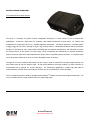
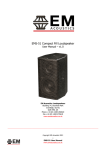
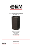
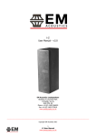
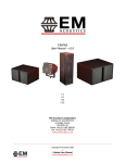
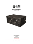
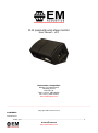
M-12 passive/bi-amp stage monitor
User Manual – v3.0
EM Acoustics Loudspeakers
Building 74, Dunsfold Park
Cranleigh, Surrey
GU6 8TB, UK
Phone +44 (0) 1483 266520
Fax +44 (0) 1483 275619
www.emacoustics.co.uk
_________________________________________________________________________________________
Copyright EM Acoustics 2013
CONTENTS
Introduction
Thank you ...…………………………………………………………………………………………………………………… 3
1
M-12 User Manual
www.emacoustics.co.uk
Unpacking ………………………………………………………………………………………………………………………. 3
Declaration of Conformity ……………………………………………………………………………………………… 3
Product Range Overview
M-12 passive/biamp two-way monitor enclosure ………………………………………………………….4
System Set-up
Safety Considerations……………………………………………………………………………………………………….5
Cabling & Amplifier selection …………………………………………………………………………………………..6
M-12 monitors in use .... ………………………………………………………………………………………………….7
Maintenance
M-12 Drive Unit Service …….…………………………………………………………………………………………… 8
Warranty ……………………………………………………………………………………………………………………………………...9
Appendix A – Technical Specifications ……………………………………………………………………………………….10
2
M-12 User Manual
www.emacoustics.co.uk
INTRODUCTION
Thank you
Thank you for purchasing the acclaimed M-12 stage monitor from EM Acoustics. The M-12 has been carefully
designed and rigorously tested to ensure years of flawless operation and unprecedented sonic quality.
EM
Acoustics Monitors are designed to provide a smooth and coherent frequency and phase response, while having
enough SPL capability where required – and consequently are equally at home for discreet classical or corporate
applications, or in louder touring roles.
Please ensure that you read this manual carefully before use, and that you keep it to hand should you need it for
further reference. Furthermore, should you have any difficulties please do not hesitate in contacting your EM
Acoustics dealer, or email [email protected] for further assistance.
Unpacking
Every EM Acoustics product is built to the highest standard and thoroughly tested before it leaves our factory.
After unpacking your loudspeaker, please inspect it carefully for any signs of transit damage. If such damage is
found, please notify the carrier at once to instigate a claim. It is suggested that you retain all packaging for future
re-shipment.
DECLARATION OF CONFORMITY
The products contained within this manual conform to the requirements of the EMC
Directive 89/336/EEC, amended by 92/31/EEC and to the requirements of the Low
Voltage Directive 73/23/EEC amended by 93/68/EEC.
Standards Applied:
EMC
Emission
EN55103-1:1996
Immunity
EN55103-2:1996
Electrical Safety
EN60065:1993
RECYCLING
This product and its packaging constitute the applicable product according to the WEEE directive.
Please ensure that at the end of the working life of this product, it is disposed of sensibly in
accordance with local and national recycling regulations. The packaging supplied with this product
is recyclable. Please retain all packaging, however if disposing of this packaging please ensure
that you comply with local recycling regulations. These products also all comply to the RoHS
Directive 2002/95/EC.
3
M-12 User Manual
www.emacoustics.co.uk
PRODUCT RANGE OVERVIEW
M-12 passive/bi-amp stage monitor
The M-12 is a compact, low-profile monitor loudspeaker designed for a wide variety of low to medium SPL
applications. It features a high-power 12” (305mm) reflex loaded neodymium LF driver and a 1.4” (36mm) exit
neodymium HF compression driver on a variable dispersion waveguide. This device produces a coverage pattern
of 90 H x 40 V at one metre, reducing to 50 H x 40 V at three metres. This dispersion pattern allows a performer
freedom of movement at close range whilst minimising spill into adjacent microphones, and effectively increases
the forward throw of the monitor at longer range. These components are matched by an internal asymmetric
passive crossover network for unprecedented sonic quality from a completely passive enclosure. A recessed switch
on the front panel allows the M-12 to be used in biamplified mode if required.
Through the use of two different side angles, the M-12 can be used for normal front-of-stage usage and also as a
close-range drum fill with the steeper angle. As with all EM Acoustics full-range products, no active controller or
programmed EQ is required for correct operation.
For demanding applications, a 60Hz high pass filter is
recommended to increase drive unit headroom however this is not essential for normal operation.
The M-12 features steel bar handles, multiple Neutrik SpeakonTM NL4MP connectors and rugged construction. The
M-12 is available as left or right handed versions to make stage pairs.
4
M-12 User Manual
www.emacoustics.co.uk
SYSTEM SET-UP
Safety Considerations
Loudspeaker systems are potentially dangerous objects if used incorrectly.
Please ensure that you read this
section fully, and contact EM Acoustics or your local dealer should you be in any doubt over correct operation
procedures.
Professional loudspeaker systems are capable of producing damage-inducing sound pressure levels, and hence
care should be taken when setting your system up, particularly when it comes to loudspeaker placement within a
venue. Damage to the ear can result from levels above 90dB under prolonged exposure.
Cabling and Amplifier Selection
The M-12 is designed to be used with professional power amplifiers providing the following power outputs:
M-12 (passive)
960W/channel into eight ohms
M-12 LF (biamp)
800W/channel into eight ohms
M-12 HF (biamp)
160W/channel into eight ohms
A small power amplifier working too hard is more likely to damage a loudspeaker than a large power amplifier
working within its operating range!
It is good practice to use an amplifier equal to the program power rating of the loudspeaker – so as to retain
sufficient headroom and good dynamic range. Care should be taken during operation to avoid amplifier clipping –
as this can cause serious damage to your loudspeakers. If in doubt, please contact your dealer who will be happy
to assist you in correct amplifier choice and setup.
5
M-12 User Manual
www.emacoustics.co.uk
Cabling
The M-12 supplied with Neutrik SpeakonTM NL4 connectors, wired pin 1+/1- in passive mode with 2+/2- as linkthrough, and 1+/1- LF, 2+/2- HF when in biamp mode. It is recommended that the resistance of your cable is less
than one tenth of the nominal system impedance. Given below are the recommended maximum cable lengths for
different cross-sections and impedances.
Conductor Cross Sectional Area
Maximum Recommended Cable Length
4 ohms
8 ohms
16 ohms
2
11m
22m
44m
1.5mm2
17m
34m
68m
2.0mm
2
22m
44m
88m
2.5mm
2
29m
58m
116m
4.0mm
2
44m
88m
176m
6.0mm
2
66m
132m
264m
1.0mm
6
M-12 User Manual
www.emacoustics.co.uk
M-12 MONITORS IN USE
The M-12 monitors were designed to deliver unprecedented performance without the expensive requirement of
active controllers and dual amplifier channels. Although the M-12 monitors can be used in biamplified format, EM
Acoustics recommend use in passive format as this is how they were intended to be used.
STAGE ORIENTATION
The M-12 is supplied as left & right-handed pairs. As the low and high frequency components sit side by side on
the baffle, the two versions are mirror images of each other. It is the monitor engineer or artist’s preference as to
whether the enclosures are arranged horns-in or horns-out when used in pairs – as these two different
arrangements will give a different sonic image. To arrange horns-out (which is what EM Acoustics recommend for
the most balanced and even response), look at the front face of the enclosure with the product label and ports.
The HF drive unit sits on the side of the enclosure with the ports on – and as such you would arrange the
enclosures “ports-out”. As a starting position, we would suggest positioning the monitors half a metre apart,
angled in at about thirty degrees (Fig 1).
BI-AMPLIFIED OPERATION
On the front panel of the M-12, beside the connector/label panel is a machined slot. Using a screwdriver, the
switch concealed inside this slot can be operated to change the M-12 from passive to bi-amp operation. In bi-amp
mode, pins 1+/1- connect to the LF drive unit, and pins 2+/2- connect to the HF unit. You will need two amplifier
channels and an external DSP processor. Please contact EM Acoustics directly for the appropriate settings for your
M-12 as they depend on the amplifier and DSP processor being used.
7
M-12 User Manual
www.emacoustics.co.uk
MAINTENANCE
Your EM Acoustics loudspeakers have been rigorously tested before they leave our factory, to ensure that they give
you a lifetime of flawless operation. Should any of your drive units fail and need replacing, please follow the
guidelines below.
M-12: Low Frequency Drive Unit
1. Using a PZ2 screwdriver, undo the three countersunk machine screws on each side of the loudspeaker – this
will allow you to remove the front grille.
2. Using a 5mm Allen key, remove the six M6 socket-head bolts holding the drive unit in place, and keep them
safe – ensuring you have collected both the shake-proof and flat washers for each bolt. Gently lift the drive
unit out of its locating hole – please take care as it is heavy! You may find you need to insert a flat bladed
screwdriver between the drive unit and recess to aid in lifting it out. Carefully disconnect the cables from the
drive unit.
3. To reinstate the driver, simply reverse the above procedure. Please observe the correct polarity – red cable to
positive terminal, black cable to negative.
4. Reinstate the grille by positioning it in place and gently pressing it into position. Note the cut-away parts of
the side flange of the grille – this cutout fits over the HF waveguide. Once the grille is in position, replace the
six bolts finger-tight, before tightening again with a PZ2 screwdriver.
M-12: High Frequency Drive Unit
1. Using a PZ2 screwdriver, undo the three countersunk machine screws on each side of the loudspeaker – this
will allow you to remove the front grille.
2. Using a 4mm Allen key, undo the eight bolts holding the HF waveguide in place. Once these are removed,
gently lift the waveguide out of the enclosure. Disconnect the cables and the drive unit is now free to be
removed.
3. To remove the drive unit from the waveguide, undo the four nuts that attach the drive unit to the waveguide
using a 13mm spanner.
4. To reinstate the drive unit, reconnect the cables (white cable to positive terminal, yellow cable to negative)
and carefully replace the waveguide into its hole. Retighten the mounting bolts.
5. Reinstate the grille by positioning it in place and gently pressing it into position. Note the cut-away parts of
the side flange of the grille – this cutout fits over the HF waveguide. Once the grille is in position, replace the
six bolts finger-tight, before tightening again with a PZ2 screwdriver.
8
M-12 User Manual
www.emacoustics.co.uk
WARRANTY
Limited Warranty
This EM Acoustics loudspeaker product is warranted to the original end-user purchaser and all subsequent owners
for a period of three years from the original date of purchase.
Warranty Coverage
This warranty covers defects in materials and workmanship. It does not include:
Damage or failure caused by accident, misuse, neglect, abuse or modification by any person other than an
authorised EM Acoustics representative.
Damage or failure caused by operating the loudspeaker product contrary to the instructions contained within
this manual.
Damage caused during shipment.
Claims based on any misrepresentation by the seller.
Products which contain anything other than the original components (or EM Acoustics factory supplied spare
parts).
Products on which the serial number has been removed, altered or defaced.
Returning your EM Acoustics loudspeaker
Should your EM Acoustics loudspeaker develop a fault, please return it (freight prepaid) in its original packaging,
along with proof of purchase to your local dealer or to:
EM Acoustics (Returns Department), Building 74, Dunsfold Park, Cranleigh, Surrey, GU6 8TB, UK
including a description of the suspected fault. Serial numbers must be quoted in all correspondence relating to the
claim. EM Acoustics or its representatives are in no way liable for any loss or damage in transit, and hence it is
recommended that the sender insure the shipment. EM Acoustics will pay for return freight should the repair be
covered under warranty.
EM Acoustics’ liability is to the replacement or repair (at our discretion) of any defective components, and as such
are not liable for any incidental and consequential damages including (without limitation) injury to persons,
damage to property or loss of use.
This warranty is exclusive and no other warranty is expressed or implied. This warranty is also in
addition to – and in no way detracts from – your statutory rights as a consumer.
9
M-12 User Manual
www.emacoustics.co.uk
APPENDIX A – TECHNICAL SPECIFICATIONS
EM Acoustics operates a continuous process of research and development, and as such reserves the right to alter specifications without notice.
M-12
Enclosure Type:
2-way, reflex loaded, variable dispersion
Dimensions (HxWxD, mm/ins):
368/14.5 x 588/23.1 x 444/17.5
Net Weight:
26kg (57.2lbs)
Frequency Response (+/- 3dB):
65Hz – 20KHz
Sensitivity:
99dB, 1W/1m
Dispersion:
90 H x 40 V (@ 1 metre)
50 H x 40 V (@ 3 metres)
Drive Units:
12” (305mm) neodymium LF cone drive unit
1.4” (36mm) exit neodymium HF compression drive unit
Power Handling:
480W RMS, 960W Program
Maximum SPL:
130dB continuous, 136dB peak
Nominal Impedance:
8 ohms
Crossover:
asymmetric internal passive/biamp external active
Connectors:
6 x Neutrik SpeakonTM NL4MP
Enclosure:
18mm (3/4”) Finnish Birch plywood
Grille:
hex-punched steel backed with acoustically transparent foam
Options:
Colours/Weather Protection
Spares & Accessories:
DU-1206 12” (305mm) LF drive unit
CDU-1401 HF compression drive unit
RK-1206 recone kit
RD-1401 replacement diaphragm
RFG-M12 replacement foam/grille
PX-M12 passive crossover network
10
M-12 User Manual
www.emacoustics.co.uk