1
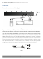
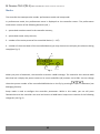
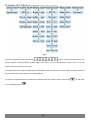
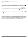
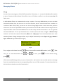
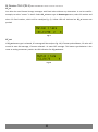
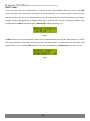
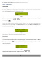
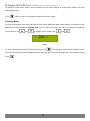
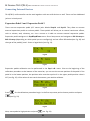
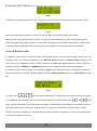
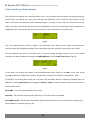
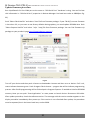
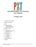
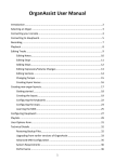
BJ Devices TB-12(TB-5) MIDI CONTROLLER. Owner’s manual. Version2.3 BJ Devices TB-12(5) MIDI FOOT CONTROLLER OWNER’S MANUAL 2 BJ Devices TB-12(TB-5) MIDI CONTROLLER. Owner’s manual. Version2.3 Index Specifications 5 Package Contains 6 Connections 7 Controls 8 Powering Up 9 Modes 10 MIDI Setup 12 Managing Presets 13 Managing Effects 14 SHIFT mode 16 TAP Tempo 17 Banks management 18 Connecting External Devices 20 Expression Pedal 1 and Expression Pedal 2 20 External Bank Switcher 21 Relay Switch 22 Tuner and Preset Name Display 23 Using Controller with Guitar Rig, Amplitube and Other Similar Software 25 Firmware Update 26 Driver and software installation 26 Update firmware procedure 27 Contacts 28 3 BJ Devices TB-12(TB-5) MIDI CONTROLLER. Owner’s manual. Version2.3 Feature Highlights Large alphanumerical backlit LCD screen (2 lines, up to 16 characters each) Heavy-duty footswitch buttons Support for phantom power over MIDI 30 banks with up to 12 (5) presets per each bank (depending on the footswitch configuration) 12 (5) footswitches assignable to preset, effect (instant access switch) or bank selection 16 MIDI channels; any 2 channels may be selected to send and receive midi messages simultaneously Jacks for 2 expression pedals Support for external expansion devices (for example, external bank selection footswitches) Preset names are displayed dynamically as they load and IA status LEDs show the active effect(s) of the currently loaded preset TAP TEMPO support Four relay jacks for remote control of external devices, for example for guitar amp channel switching Onboard memory stores up to 360 (150) presets in 30 banks Each of the 30 banks can be individually named (bank name up to 12 characters) Tuner and preset name support Current bank number and MIDI channel is saved upon power off USB for firmware upgrade and external application control (AmpliTube, Guitar Rig, etc.) Rugged and road-ready steel chassis 4 BJ Devices TB-12(TB-5) MIDI CONTROLLER. Owner’s manual. Version2.3 Specifications MIDI Type 5-pin jacks - MIDI IN and MIDI OUT Screen Type backlit LCD, alphanumerical (2 lines 16 characters each) Other switching jacks Type 2 x 1/4" stereo jack – relay switches2 x 1/4" stereo jack – expression pedal switches Type USB type B – USB OUT Power consumption Type DC Voltage 7-12 V, 350 mA Dimensions and weight TB-12: 420mm x 180mm x 55mm / 2kg TB-5: 210mm x 180mm x 55mm / 1kg 5 BJ Devices TB-12(TB-5) MIDI CONTROLLER. Owner’s manual. Version2.3 Package Contains 1. TB-12(TB-5) – 1pcs. 2. Power adapter - 1pcs. 6 BJ Devices TB-12(TB-5) MIDI CONTROLLER. Owner’s manual. Version2.3 Connections The controller connections are as follows (Fig. 1). Fig. 1 Fig. 1 shows the back panel of TB-12; the back panel of TB-5 is identical in terms of connections, so you can use the same cables. MIDI OUT: use this port to connect the controller to MIDI IN port of your MIDI device. Use a MIDI DIN5pin-DIN5pin cable. MIDI IN: use this port to transmit midi data to the controller from the MIDI OUT port of your MIDI device (for example to transfer tuner data or footswitch status). Use a MIDI DIN5pin-DIN5pin cable. To use relay jacks SW1/2 and SW3/4 you will need a 1/4" stereo jack – 1/4" stereo jack cable. One end of the cable is connected to SW jack of the controller and the other - to the footswitch jack of a guitar amp or any other similar device To connect an volume pedal to Exp.1 or Exp.2 jack you will need either an identical cable or a Y-cable (stereo 1/4" jack – two mono 1/4" jacks). See Fig. 2 for the wiring diagram. It depends on the expression pedal, which of the two cable types you should use. Fig. 2 7 BJ Devices TB-12(TB-5) MIDI CONTROLLER. Owner’s manual. Version2.3 Controls Fig. 3 The and buttons (see Fig. 3) can be used in two ways. Further in this manual, depending on the feature, only one of the button names (either SETUP or NO and either LOAD or OK) will be mentioned. SETUP – activates the setup mode (see Modes) NO – exits the current mode without saving. LOAD – activates Bank Load mode (see Loading Banks) OK – confirms the current selection or saves the settings. , , , - buttons used to navigate the menus and change parameter values. Footswitches 1-12 (1-5 for TB5) may be used to select Presets (see Managing Presets) or as Instant Access switches to turn on/off individual effects within a preset (see Managing Effects) or to change the controller’s banks. Any of the footswitches can be assigned one of the three functions via the menu. 8 BJ Devices TB-12(TB-5) MIDI CONTROLLER. Owner’s manual. Version2.3 Powering Up There are two ways of supplying power to your controller: - You can connect an DC adaptor (7-12V, 350mA, center negative) to the jack on the back panel of the controller. - Alternatively, you can supply phantom power via the MIDI cable. Phantom power is received at MIDI OUT port of the controller. Please note that we use 5 pin (NOT 7 pin) MIDI OUT port that receives phantom power on pins 2 and 4 (outer pins, see Fig. 4). outside view of the connector - + Fig. 4 Phantom power the controller receives is also available on pins 2 and 4 of the MIDI IN port so that you can daisy-chain several phantom powered MIDI devices. Three seconds after the power is supplied to the controller, the firmware version is displayed on the screen, the LEDs blink several times and the controller is ready for operation. 9 BJ Devices TB-12(TB-5) MIDI CONTROLLER. Owner’s manual. Version2.3 Modes The controller has two operation modes: performance mode and setup mode. In performance mode, the performance menu is displayed on the controller screen. The performance mode menu consists of the following elements (see ): 1 – preset bank number stored in the controller memory; 2 – preset bank name set by the user; 3 – number of the active preset of the controlled device (1 – 127) 4 – number of the active bank of the controlled device (you may choose not to display this element during setup)(see Fig. 5) 1 2 3 4 Fig. 5 When you press a footswitch, the controller transmits a MIDI message. The controller also receives MIDI data that lets it display the preset names on its screen and effect (IA) statuses via its LEDs. You can change the active preset number of the controlled MIDI device on the fly by pressing , buttons (see Managing Presets). Setup mode is used to configure the controller parameters. While in this mode, you can still press footswitches and the controller can send and receive all MIDI data. Setup menu consists of the following categories (see Fig. 6) 10 BJ Devices TB-12(TB-5) MIDI CONTROLLER. Owner’s manual. Version2.3 Fig. 6 You can navigate the menu by pressing , , , buttons. To enter Setup mode, press SETUP button. Pressing SETUP button again will return you to the previous menu level or to the performance mode of the controller. For quick load of the required bank press LOAD button and the controller will be ready to load the desired bank instantly (for more details see Loading Banks). To save any changed value of a parameter selected from the menu or bank name press menu (category) press . 11 , to leave the BJ Devices TB-12(TB-5) MIDI CONTROLLER. Owner’s manual. Version2.3 MIDI Setup In Performance mode, press SETUP and navigate to System Setup by pressing or . Press to edit. You can select any two MIDI channels that the controller will work with by pressing don’t need two MIDI channels you can deactivate one of them by selecting or . Set the MIDI channel number that your external MIDI device is using by pressing Press . If you or . . The controller will save the entered value. Press SETUP and the controller will return to Performance mode. If the settings are correct, your MIDI device will activate the desired preset if it exists it its memory. In the same menu, you can choose to send Bank Change message together with Program Change message (preset change). This comes handy when you control, for example, AXE-FX where the presets are organized in banks. To do so, navigate to PRG CH MODE submenu and select PC+Select Bank parameter. 12 BJ Devices TB-12(TB-5) MIDI CONTROLLER. Owner’s manual. Version2.3 Managing Presets TB-12(TB-5) allows you to access up to 12(5) presets of a controlled MIDI device. You can program each footswitch (or only some of them) to activate a preset of a MIDI controlled device. This preset is displayed in the lower line of the screen (in Performance mode) and the LED of the corresponding footswitch lights red. Enter Setup mode and navigate to Buttons Setup submenu to choose, which footswitches will switch presets. To set the footswitches as preset change switches (Program Change messages will be sent) set the Type to PC in Button 1 type – Button 12 type submenus.(see Fig. 7) Fig. 7 The preset number is specified in Performance mode with and buttons; all buttons of the controller will stay active. When you set preset number in Performance mode, keep in mind that you do so for the currently active footswitch. To set preset number for a different footswitch, press that footswitch first. Pressing a preset change footswitch will initiate a Program Change message with the desired preset number. Don’t forget to save the changes - all the changes you make will be lost when you switch the bank or turn the controller off unless you save the changes in the internal memory of the controller. To do so, save the bank (see Saving Banks). 13 BJ Devices TB-12(TB-5) MIDI CONTROLLER. Owner’s manual. Version2.3 Managing Effects CC_tg You can choose to assign any of the 12(5) footswitches IA functions, i.e. to control individual effects within a preset. Footswitch LEDs indicate if the effect is on or off. When an effect is on, the corresponding LED lights green. A MIDI device effects are associated with unique numbers. For many MIDI devices you can set these command numbers from the menu or via the learn function, but for some devices these numbers are ‘hardwired’. With TB-12 (TB-5), you can set the Control Change (CC) number of each button that performs IA function. To set the required CC numbers you should find out the CC numbers that are assigned to the respective effects of the controlled MIDI device. You can usually find this information in the user guide of the controlled device. To set up a footswitch as an IA switch, enter the menu, navigate to Buttons setup submenu and select the required footswitch (Button 1 – 12(5) type). To set the footswitches as IA state switches (Control Change messages will be sent, IA ON/OFF alternation) set the Type to CC_tg in Button 1 type – Button 12 type submenus(see Fig. 8). Fig. 8 First, navigate to the lower line with that, you can select CC number with press button, then to effect number (CC number) – with and . To save, press . After . To exit without saving, . LEDs status (on/off) change when you press a footswitch as well as when the controller receives a message from the controlled device that the corresponding effect is on or off (for example, if it was activated on the device without using the controller footswitches). 14 BJ Devices TB-12(TB-5) MIDI CONTROLLER. Owner’s manual. Version2.3 CC_ct You able also send Control change messages with fixed value without any alternation. It can be used for example, to select “scenes” in AxeFx. Select CC_ct button type in Button type menu, select CC number and when CC fixed number, which will be send(see Fig. 9). Yellow LED will indicate last CC_ct button was pushed. Fig. 9 CC_mt If CC_mt button type is selected, CC message will be sent(see Fig. 10). If button pushed down, CC value will match IA state ON message, if button released – IA state OFF message. This button type behavior is the same as analog momentary switch. No LED indication for CC_mt button. Fig. 10 15 BJ Devices TB-12(TB-5) MIDI CONTROLLER. Owner’s manual. Version2.3 SHIFT mode In case you need more than 12(5) buttons to control presets and individual effects you can use the Shift mode, which gives you essentially a dual layout of the footswitches. In this mode, layout 1 will become the one you usually have and use in Performance mode, while layout 2 will turn all footswitches into Control changes senders (CC_tg, CC_ct or CC_mt button type), and the LEDs will act accordingly. Buttons type configuration for Shift mode performed in Button shift submenus(see Fig. 11). Fig. 11 In Shift mode, one of the footswitches allows you to switch between the layouts. When layout 1 is active Shift mode footswitch LED blinks with long pauses, and when layout 2 is active the same LED blinks with short pauses. You can activate Shift mode for any of the footswitches in Button type menu (see Fig. 12). Fig. 12 16 BJ Devices TB-12(TB-5) MIDI CONTROLLER. Owner’s manual. Version2.3 TAP Tempo You can tap tempo by repeatedly hitting the footswitch of the selected preset, which will send tap tempo CC message. Enter Setup menu and navigate to Exp&Tap&Tuner submenu, then select TAP.(see Fig. 13) Fig. 13 Choose CC number corresponding to the one of the controlled device. With each repeated tap this CC will be sent to the controlled device. Choose tempo button behavior from 3 possible cases - CC_tg, CC_ct or CC_mt (see Managing Effects). Thus, TAP TEMPO feature is always available without assigning a separate button. Internal generated tap-tempo is not accompanied by LED flashing; no additional information is shown on the display as well. But TB-12(5) can display tempo from income SysEx MIDI messages if data format known. Fractal Audio AxeFx (standard, ultra, II, II XL) devices and Kemper Profiler Amplifier messages are currently supported. You can choose TAP indication in Tap display menu(see Fig. 14). Fig. 14 Following types available: «SCRN» - indication on right side of TB-12(5) screen «LED1» - «LED12» - indication is assigned to a particular LED. All other indication on this LED will not active. «PRESET» - indication is assigned to a current active preset LED «OFF» - indication disabled Be sure you set correct target device in System setup -> Target device menu, or set in to Auto detect mode(see Fig. 15). Fig. 15 17 BJ Devices TB-12(TB-5) MIDI CONTROLLER. Owner’s manual. Version2.3 Banks management Loading Banks By default, LOAD button is used to load the controller banks. To load a bank when in Performance mode, press LOAD. Load bank menu will be displayed(see Fig. 16). Fig. 16 Select the required bank with bank load press and , bank name will be displayed in the lower line To confirm . You can also change banks up and down on-the-fly. To do so, you will need to program any two footswitches out of 12 (5) available. Enter Buttons Setup menu and assign BNKup and BNKdown to the desired footswitches (see Fig. 17). Fig. 17 When you do so, LEDs of these footswitches will become inactive. Saving Banks To save bank setting enter setup mode by pressing Setup button. When in setup mode, navigate to Save to Bank submenu and press . You will see Select bank: [current bank number] and bank name in the upper line(see Fig. 18). Fig. 18 Choose the bank number which setting you want to save with 18 , . BJ Devices TB-12(TB-5) MIDI CONTROLLER. Owner’s manual. Version2.3 ATTENTION: unlike bank names, preset numbers are set and changed in Performance mode, see par.6 Managing Presets. Press again to save the settings and load Performance mode. Renaming Banks For your convenience, each bank can have its own name. Maximum bank name length is 12 symbols. Enter Setup menu and navigate to Rename bank. You will see a cursor(see Fig. 19). To choose the symbol at cursor position use and ; to change cursor position use and . Fig. 19 To finish editing bank name and save the results press . The new bank name will be loaded into the controller memory and will be displayed upon the next load. To finish editing bank name without saving press . 19 BJ Devices TB-12(TB-5) MIDI CONTROLLER. Owner’s manual. Version2.3 Connecting External Devices TB-12(TB-5) midi-controller can be used together with non-midi devices as well. There are four dedicated jacks on its back panel. Expression Pedal 1 and Expression Pedal 2 There are two expression pedal 1/4" stereo jacks labeled Exp.P1 and Exp.P2. They allow to connect external expression pedals or volume pedals. These pedals will allow you to control continuous effects, such as volume, wah, whammy, etc. Use a stereo or Y-cable to connect external expression pedals. Expression pedal settings are in Exp&Tap&Tuner menu. Enter Setup menu and navigate to EXP P1 setup or EXP P2 setup (depending on which pedal you are configuring) and set effect CC number(see Fig. 20) and the type of the pedal(s) used - linear or logarithmic (see Fig. 21). Fig. 20 Fig. 21 Expression pedals calibration can be performed in the Exp P clb. menu. Prior to the beginning of the calibration procedure at the bottom of the menu bar, you can see the current position of the pedal. If the pedal is in the lowest position, the position value must be equal to 0 in the upper pedal position value is 127 (see Fig. 22). If the values do not reach the extreme, you need to calibrate. Fig. 22 Press for the calibration procedure begin. In the first step move peal to lowest position and press (see Fig. 23) Fig. 23 Next, move pedal to high position and press (см. Fig. 24) 20 BJ Devices TB-12(TB-5) MIDI CONTROLLER. Owner’s manual. Version2.3 Fig. 24 If calibration complete successful, “OK” message will be shown on screen during short time (see Fig. 25) Fig. 25 After the calibration procedure is necessary to check again the extreme values of the pedal. Warning! Expression pedals sockets in TB-12 (5) have a non-standard polarity. We recommend using an expression pedal with polarity switcher, such as Mission Engineering SP-1R and M-Audio EX-P. When using a volume pedal polarity determined by turning the insert-cable to IN and OUT sockets of the pedal. External Bank Switcher By default, LOAD button is used to load the controller banks. You can always load a bank from the controller menu. This does not depend on the Bank sw mode submenu in Buttons setup. However, you can choose two additional modes of bank switching in Bank sw mode submenu. These modes are: controller buttons (if BNKup and BNKdown commands are assigned to them) and external pedals. An external bank switcher pedal is connected to Exp.P1 jack (instead of the first expression pedal). To activate the feature, attach the pedal to Ext.1 jack and set Bank sw mode submenu to EXT ON P1.(see Fig. 26) Fig. 26 To check, press or on the external footswitch. The bank you are switching to will be shown on the display and channel LEDs will start blinking. Select the desired bank with and , and press a preset footswitch. This will activate the preset in the bank you have selected. If you don’t press any of the footswitches after you press channel switch, the previously used bank number will be retained. Caution: Use only manufacturer supplied external pedal (optionally supplied) or consult the manufacturer on the type of pedal you can use. 21 BJ Devices TB-12(TB-5) MIDI CONTROLLER. Owner’s manual. Version2.3 Relay Switch There are SW1/2 and SW3/4 1/4" stereo jacks on TB-12(TB-5) rear panel that can be used to connect to footswitch inputs of a guitar amp, preamp or other similar gear. Each stereo jack has 2 relays. You can program each relay status in Relay setup menu and save it. If no preset change (Program Change) buttons are assigned, relay submenu will display No PC buttons(see Fig. 27) and you won’t be able to program relay switches. Fig. 27 22 BJ Devices TB-12(TB-5) MIDI CONTROLLER. Owner’s manual. Version2.3 Tuner and Preset Name Display The controller can display the controlled device tuner. You can easily tune your guitar on stage during your performance. To activate the tuner, press and hold the footswitch of the currently active preset. To exit tuner mode press and hold the same footswitch again. Currently, tuners of the TC Electronic units (GMajor, G-Force), Fractal Audio Systems (Axe-Fx Standard/Ultra, Axe-Fx II) and Kemper Profiler Amplifier are supported. When you activate the tuner the controller screen will look like this (see Fig. 28). Fig. 28 This is the default setting, when no signal at the processor input. When there is signal at the processor input the letter will change depending on the input signal (just like the built-in processor tuner itself). For some devices, like AxeFx, to activate tuner, a Control Change message must be sent. To set the CC number enter Setup mode and navigate to Exp&Tap&Tuner, then to Send Tuner CC(see Fig. 29). Fig. 29 In the lower line specify CC number to activate/deactivate tuner mode, or set NO. In this case no CC message will be sent. When tuner mode is activated the controller sends 0x5F, to deactivate - 0x00. TB-12(TB-5) can show preset names on its screen if the controller device is capable of sending them via MIDI OUT. Enter System Setup and navigate to Show pr. name to specify if preset name must be shown in Performance mode. Show BNK – the controller shows bank name only Show PR – the controller shows preset name only if this information is available Show BNK and PR – the controller shows both preset and bank name in turns (each name is displayed for approximately 3 seconds). (see Fig. 30) 23 BJ Devices TB-12(TB-5) MIDI CONTROLLER. Owner’s manual. Version2.3 Fig. 30 Be sure you set correct target device in System setup -> Target device menu, or set in to Auto detect mode(see Fig. 15) 24 BJ Devices TB-12(TB-5) MIDI CONTROLLER. Owner’s manual. Version2.3 Using Controller with Guitar Rig, Amplitube and Other Similar Software Midi controllers BJ Devices TB-12 and TB-5 have a USB interface for connection to a computer, but are not PC-compatible MIDI devices. In order to use the controller as a MIDI device via USB, follow these steps: 1. Install serial to midi converter Hailess MIDI http://projectgus.github.io/hairless-midiserial/ 2. Install virtual MIDI port LOOPMidi http://www.tobias-erichsen.de/software/loopmidi.html 3. Install USB-COM driver (in most http://www.ftdichip.com/Drivers/VCP.htm cases this installation starts automatically.) 4. Run Hairless MIDI<->Serial Bridge, choose COM port which is according TB-12(5) com port, assign COM port to midi in device LOOPMidi, set baud rate 56000. 5. IN TB-12 (5) set System setup -> USB baudrate vale to 56000(see Fig. 31) Fig. 31 Now you can connect your software to LOOPMidi port, all MIDI messages from TB-12(5) will be passed to LOOPMidi port. 25 BJ Devices TB-12(TB-5) MIDI CONTROLLER. Owner’s manual. Version2.3 Firmware Update 1. Download latest firmware for your device from product’s page 2. Download latest driver from http://www.ftdichip.com/Drivers/VCP.htm 3. 0Download chip45boot2 GUI software for Windows https://www.chip45.com/avr_bootloader_atmega_xmega_chip45boot2.php for MacOs http://www.definefalsetrue.com/index.php/en/Mac-OS-X/bootfeedx.html for Linux https://github.com/bullestock/c45b Driver and software installation Connect your device to computer via USB cable. You will get message about new hardware “USB Serial Port”. If driver does not be installed automatically, you have to install it manually. Use “ftdiport.inf” file from driver package. After driver is successfully installed you can find “USB Serial Port” hardware in Device Manager(see Fig. 32). Fig. 32 Install chip45boot2 GUI application. This installation is typically. 26 BJ Devices TB-12(TB-5) MIDI CONTROLLER. Owner’s manual. Version2.3 Update firmware procedure Run chip45boot2 GUI. Set COM port to the same as “USB Serial Port” hardware is using. You can find out this information in “USB Serial Port” properties in Devices Manager. Set baud rate value to 28800(see Fig. 33). Push “Select Flash HexFile” and select *.hex file from firmware package. If your TB-12(5) current firmware is less when 2.0, or you want to set factory defaults during update, you need update EEPROM also. Push “Select Eeprom HexFile” and select *.e(or *.eep) file from firmware package. You can find firmware zip package on your product’s page http://www.bjdevices.com/en/. Fig. 33 Turn off your device and then push «Connect to bootloader» button and then turn on device. If all is ok, status indicator becomes green. Push «Program Flash» button – progress bar will be indicate programming process. After FLASH programming will be finished push «Program Eeprom» if needed to initialize EEPROM memory. Now you can push “Start Application” or reset power to launch device. Disconnect USB cable. After update procedure, check the software version. The message with the version number appears on the display controller immediately after power-up. If the version is not refreshed after update, the procedure must be repeated, but in the lower baud rate, such as 9600. 27 BJ Devices TB-12(TB-5) MIDI CONTROLLER. Owner’s manual. Version2.3 Contacts BJ Devices. Russia, Penza. http://www.bjdevices.com/en e-mail: [email protected] 28