1
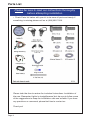
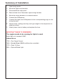
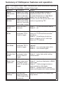
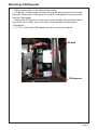
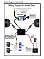
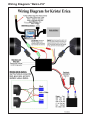
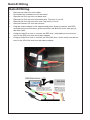
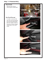
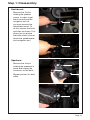
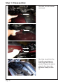
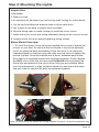
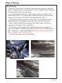
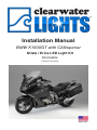
Installation Manual
BMW K1600GT with CANopener
Krista / Erica LED Light Kit
Dimmable
Patent Pending
Parts List
Please be sure to read our instructions thoroughly
before attempting installation.
• Check Parts list below with your kit to be sure all parts are handy. If
something is missing please call us at (916) 852-7029.
Please take the time to review the included instructions. Installation of
the new Clearwater Lights is straightforward, but be sure to follow some
of the suggestions to keep the installation safe and reliable. If you have
any questions or comments please feel free to contact us.
Thank you!
Page 2
Summary of Installation
1.
2.
3.
4.
5.
6.
7.
Open body panels
8.
Secure wires, making sure they won’t get caught in the suspension or
steering column.
9.
Attach power lines to battery and replace the fuse.
Mount the lights and brackets.
Disassamble the side panel.
Remove fuse from Clearwater Lights wiring harness
Mount the wiring harness to a secure location.
Connect the CANopener
Connect the lights and CANopener to their corresponding plugs on the
wiring harness.
IMPORTANT THINGS TO REMEMBER!
The engine needs to be running for lights to work
Brake light not to exceed 1AMP
Abbreviations
TSC = Turn Signal Cancel
WW = WonderWheel (BMW multifunction controller)
FTP = Flash To Pass
OBL = Optional Brake Light
Summary of CANopener features and operation
TSC = Turn Signal Cancel WW = WonderWheel (BMW multifunction controller)
FTP = Flash To Pass OBL = Optional Brake Light
Function
Command
Modes
Darla/
Glenda dimmer
Press(TSC), then
hold control wheel
left for 2 seconds
and rotate to adjust
Erica/Krista
dimmer
Press(TSC), then
hold control wheel
right for 2 seconds
and rotate to adjust
Rotate WonderWheel to select 10
brightness levels (10% to 100%)
To adjust brightness on High Beam
Mode, turn on high beam first
Dimmer control will cancel after 2 seconds or by pressing TSC
Erica/Krista
on/off
Hold TSC for 2
seconds
Mode 1 – on and dimmable (default)
Mode 2 – off
High Beam
Mode
Hold brake lever
and press FTP 3
times to toggle
Mode 1 – all lights on 100% with high
beam or FTP, Erica/Krista must be
turned on
Mode 2 – Erica/Krista off with low
beam, all lights on 100% with high
beam or FTP (default)
Horn Activation Mode
Hold brake lever
and press TSC 3
times to toggle
Mode 1 – horn does not affect lights
(default)
Mode 2 – horn activates lights 100%
Mode 3 – horn strobes lights
Hazard
Flasher Alert
Mode
Hold hazard switch Mode 1 – no flash (default)
Mode 2 – lights flash while holding
and press brake
hazard switch
lever 3 times to
toggle
Clearwater
Brake Light
(optional)
While stationary,
press brake lever
or pedal 5 times
within 5 seconds to
toggle
Reset Default Hold left turn
Settings
signal and press
FTP 6 times within
6 seconds
Mode 1 – off (default)
Mode 2 – functions identically to BMW
brake light
Mode 3 – California legal strobe on
brake activation (4Hz flash)
Mode 4 – speed sensitive (flashes
faster and brighter with harder braking)
Reset all functions to the default settings above
Mouting CANopener
• Remove the seat from the bike and set aside.
• Locate the module under the seat, unplug the wiring harness from it and
plug your Clearwater CANopener in it’s place. Then plug the wiring harness
into the CANopener.
• Secure the CANopener to the plastic inner fender with provided Velcro
strip. Be sure to clean any dirt or dust from area before affixing the
CANopener.
• DO NOT mount the CANopener on top or touch the module.
Module
CANopener
Page 5
Wiring Diagram “New Install”
Wiring Diagram “Retro-Fit”
Retrofit Wiring
Retrofit Wiring
•
•
•
•
•
•
•
•
•
Remove the fuse from fuse holder.
Disconnect the connectors from the switch.
Remove the Posi-tap from low beam wire.
Remove the Posi-tap from high beam wire. Tug away or cut off.
Remove the Posi-tap from horn wire. Tug away or cut off.
Remove Dimmer Pot from the harness.
Plug the trident adapter to the appropriated place. Green connector with RED
shrinktub plug to the harness, green connector with BLACK shrink tube plug to
the data cable.
Using provided Posi-lock to connect the RED wire ( switched hot) from the harness to the RED wire from the trident adapter.
Using provided Posi-lock to connect the YELLOW wire ( switch load) from the harness to the YELLOW wire from the trident adapter.
Bike
StepPreparation:
1: Parts List
and Bike Preparation
Bike Preparation:
• First, park the motorcycle on hard pavement or concrete to insure the
bike will be stable during the installation. If you can mount the bike on a
stand with tie-down straps, this will help secure the motorcycle.
• Follow the manufacturers guidelines for disconnecting the battery. This
is important to prevent damage to the electrical system.
Krista / Erica Technical:
• Krista and Erica are very bright LED auxiliary light. Do not use these
with on coming traffic unless the dimmer is turned down all the way.
Krista and Erica are designed as an off road only light due to it’s light
output and beam pattern. The wide circular pattern is very useful in
mountain roads on a motorcycle as it keeps light on the road and in
the tree canopy. As the bike leans, light is still focused on the road. Be
certain to use the lights in a manner that does not blind oncoming traffic.
• By using a proprietary digital volume control, we can “dim” the lights
via a remote mount volume control. This rotary knob sends a digital
signal to our microprocessor that changes the pulses of electricity to the
LED’s. As we increase the time that the lights are “off” the human eye
perceives this as dimming. We switch our lights on and off at a rate of
250 times per second, every second. Increased efficiency occurs with
the dimming as well.
• Krista and Erica can also be used in a “low” beam mode and a “high”
beam mode. The factory handlebar high beam switch is used to select
the two different LED modes. Krista and Erica are easy to install and
have many, many uses.
Page 9
Step 1: Disassembly
Windshield:
Remove the 4 bolts
securing the windshield.
Gas Tank Shroud:
In order to remove the
gas tank shroud plastics
you must flip the plastic
back as shown to get to
the bolts. Follow images
continued on the next
page.
Page 10
Step
Step 1:
1: Disassembly
Parts List and Bike Preparation
Dashboard:
Remove the 2 bolts
holding the speaker
covers. In order to get
the shroud above the
navigation unit off,
you must remove the
windshield mount. To
do this remove the bolts
and clips as shown. This
allows you to remove
the black plastic shroud
above the speedometer
and navigation unit.
Speakers:
Remove the 3 bolts
holding the speakers in
place and unplug the
connector on the back.
Repeat process for both
sides.
Page 11
Step 1: Disassembly
Gas tank shroud removal
continued.
Your bike should look like
this after removing one
side of gas tank shroud
plastics. Repeat the above
steps for the other side
and we’re ready to move
on.
Page 12
Step 2: Mounting The Lights
Helpful Hint:
1. Be patient.
2. Take your time.
3. An assistant will be helpful (you will find yourself looking for a third hand).
4. Cut the zip-tie holding the antenna cable to allow cable slack.
5. Lay a towel on the body to protect from scratches.
6. Flex the fairing open to make it easier to install the mirror mount.
7. Adjust the mirror mount and fairing alternately during install of mirror mount.
8. Loosely mount the mirror before tightening fairing screws.
Mirror Mount Overview:
• To install the Krista / Erica using the supplied mirror mount, remove the
mirrors on your bike. Do one at a time to be able to look at the attached
mirror for reference when assembling. Once the mirror is off, place the
intended bracket on the bike using the bolts from the mirror to tighten the
bracket in place. Once the brackets are in place, assemble each Krista /
Erica light to its separate bracket with supplied hardware. Finally, replace
the BMW mirror bolts with the new supplied M6x20 bolts and attach the
Krista light and bracket to the mirror mount that you just installed. Make
your last adjustments to align the lights where you want them and make
one last check to see that the bolts are tightened properly.
Note: Pictures above are without the fairing attached. Photos for illustration purposes only.
Page 13
Step 2: Mounting The Lights
Under Mirror Mount:
M8x12
M6x16
(x4)
M8x12
M10x16
Aligning the Lights:
Erica and Krista are designed as auxiliary
lights, adjustment is up to the user
depending on his needs. Ask an assistant
to help you with this procedure. Make
sure the bike is on level ground and have
your assistant sit on the bike. With a right
angle board or object, position the board
on the floor and slide it up to the light.
The goal is to adjust the lights so that the
light is level with the ground. Passengers
and luggage may alter the alignment of
the light so further adjustments may be
needed. Often times it is helpful to angle
the right side light toward the right side
of the road. This helps with identifying
road terrain, potential critters, and road
hazards.
Page 14
Step 3: Wiring
Wire Routing:
• Be sure to route wires so that they cannot become tangled or caught in
either a suspension part or steering part. Check movement of both steering
and suspension before riding the bike.
• Locate the power relay box in a safe location where it is show in Fig. 1
Secure with a zip tie. It is a good idea to face the relay box with the wires
coming out the bottom. This helps keep everything dry. (Fig. 1)
• Route the two black connectors for the lights to a convenient location
where they will not interfere with steering or any other moving parts.
• Run the RED and BLACK power wire, and Data Cable along the air
intake up to the battery. (Fig. 2) and (Fig. 3)
• The BLACK power wire with the ring terminal goes to the negative ( - )
side of the battery. The RED power wire with the inline fuse holder goes to
the
positive ( + ) side of the battery. Remove the fuse while wiring the
lights to prevent any accidental shorts.
• Plug the Data Cable into the CANopener.
Fig. 1
Fig. 2
Harness Box Location
Fig. 3
Page 15
Clearwater CANopener operation and features
Summary of features
1.
Clearwater Lights dimming feature
• Independent dimming of two sets of Clearwater lights using
BMW WonderWheel (handlebar mounted rotary dimmer included for nonWonderWheel bikes)
• Brightness adjustable in 10 steps from 10-100%
2. Automatic Dimmer
• Programmable Clearwater lights dimmer setting compensates
automatically using the bike’s photocell
• Factory preset and programmable dimmers for day, night, and high
beam illumination
3. On/off function for Erica/Krista lights
• No separate switch required, uses factory turn signal cancel button
4. Horn Activation Mode
• Clearwater lights programmable to illuminate or strobe with horn
button (off road use only)
5. Hazard Flasher Alert Mode
• Clearwater lights programmable to strobe when holding the hazard
flasher button (off road use only)
6. High Beam Mode
• Clearwater Erica/Krista lights programmable to activate with high
beam or flash-to-pass button
7. Clearwater Brake Light Module (optional)
• Programmable LED brake module includes California-legal strobe
mode and speed sensitive mode
8. Auxiliary CANbus relay drives
• Auxiliary turn on (1/4 amp maximum) - YELLOW wire
• Auxiliary horn (1/4 amp maximum) - GRAY wire
• Auxiliary high beam relay drive (1/4 amp maximum) - GREEN wire
WARNING: Do not connect auxiliary accessories without a relay!
9. Factory Default Reset
• Reset all functions to the default settings
Clearwater CANopener operation and features
DIMMING CONTROL (WonderWheel equipped bikes)
Two modulated brightness channels are adjustable using the
WonderWheel:
• Each channel is programmable for ten brightness settings (10100%) in three different modes (day, night, and high beam). Settings
are stored in non-volatile memory, and will be remembered when
restarting the bike or disconnecting the battery. The dimmer is
programmed at the factory for the most useful day/night settings.
• To enter dimmer program, you now must first press the Turn Signal
Cancel (TSC) switch once before tilting the Wonderwheel Left or
Right for dimming. Press the WonderWheel to the LEFT for two
seconds to engage the Darla/Glenda channel dimmer, or press it
to the RIGHT for two seconds to engage the Erica/Krista channel
dimmer. The lights being adjusted will flash twice to confirm
programming mode. Adjust the output by rotating the WonderWheel.
• While adjusting the brightness mode, the second set of lights (if
installed) will automatically dim to their lowest setting in order to
easily observe the adjustment.
• Exit programming mode either by waiting for approximately two
seconds or pressing the turn signal cancel button. The lights will
flash once to confirm.
• Remember that each set of lights is adjustable for day, night and
high beam. Day and night settings are automatically selected by the
ambient light level reaching the bike’s photocell. To adjust the night
dimmer, simply cover the photocell at the top right corner of the dash
display using your hand or a piece of tape. Activate the high beam to
adjust the high beam setting.
WARNING: When configuring the dimmer, be sure that the WonderWheel
is not making adjustments to other functions of the onboard systems.
Turn off the entertainment system to prevent volume adjustment or
unwanted channel changes, and select the home screen on the GPS.
DIMMING CONTROL (non-WonderWheel bikes)
If the motorcycle does not have the GPS Prep Package
(WonderWheel), your light kit will come equipped with a handlebar
mounted analog/digital encoder knob for dimming control. Separate day
and night settings and the dual intensity dimmer will not be available.
ON/OFF FUNCTION FOR ERICA/KRISTA
The Erica/Krista lights can be manually deactivated. Toggle these
modes by holding the turn signal cancel button for two seconds.
• Mode 1 – on and dimmable (default)
• Mode 2 – off
Clearwater CANopener operation and features
HORN ACTIVATION MODE
The Clearwater lights can be programmed for three different modes when
the horn button is pressed. Toggle these modes by holding the brake lever
and pressing the Turn Signal Cancel button three times. The brake and
Clearwater lights flash to indicate the mode selected:
• Mode 1 – horn does not affect lights (default)
• Mode 2 – horn activates lights 100%
• Mode 3 – horn strobes lights (if two sets of Clearwater lights are
installed, they will alternate flashing)
WARNING: The use of strobe mode may not be legal on public highways.
Check your local regulations. This mode is intended for parades and
escorts under certain conditions.
HAZARD FLASHER ALERT MODE
The Clearwater lights can be programmed to strobe when the hazard
flasher button on the left grip is held down. Toggle these modes by holding
down the hazard flasher button and pressing the brake lever three times:
• Mode 1 – OFF, no flash with emergency flasher button (default)
• Mode 2 – strobe with emergency flasher button held down (if two sets
of Clearwater lights are installed, they will alternate flashing)
NOTE: Pressing the hazard flasher button activates the turn signal flashers.
Cancel the flashers with another short press of the button.
WARNING: The use of strobe mode may not be legal on public highways.
Check your local regulations. This mode is intended for parades and
escorts under certain conditions.
HIGH BEAM MODE
The Erica/Krista lights can be programmed for two modes of
operation in conjunction with high beams. Toggle these modes by holding
the brake lever and pressing flash-to-pass three times:
• Mode 1 – all Clearwater lights turn on 100% when high beam or flashto-pass is pressed. Erica/Krista use the day/night dimmed setting on
low beam. Erica/Krista lights must be turned on. (default on ver 1.5 or
greater)
• Mode 2 – HIGH BEAM ACTIVATION. All Clearwater lights turn on
100% when high beam or flash-to-pass is pressed. Erica/Krista are
turned off with low beam. Erica/Kristas do NOT need to be turned on.
(default on ver 1.6 or greater)
Clearwater CANopener operation and features
CLEARWATER BRAKE LIGHT MODULE (OPTIONAL)
A 1 AMP driver is provided for the optional Clearwater auxiliary brake light
license plate frame. There are four modes available. Toggle these modes
by pressing the brake lever or pedal five times while the bike is stationary.
The engine may be on or off. The brake lights will flash one, two, three or
four times to indicate the mode selected.
• Mode 1 – off (default).
• Mode 2 – functions identically to BMW brake light, no flash.
• Mode 3 – California legal strobe on brake activation (4Hz flash), then
continuous on as long as the brake is held.
• Mode 4 – speed sensitive mode. Bike speed and braking data is used
to modulate the flash rate.
NOTE: The auxiliary brake light is configured as an “always on” running
light at a reduced light level. When either the front or rear brake is
activated, it activates at 100% brightness. All flashing light modes are
deactivated below 5mph.
AUXILIARY CANBUS RELAY DRIVES
• Auxiliary turn on (1/4 amp maximum) Useful for turning on aux fuse
boxes or a PDM-60.
• Auxiliary horn (1/4 amp maximum) Useful for adding and aux air horn.
MUST use relay.
• Auxiliary high beam relay drive (1/4 amp maximum) Useful for adding
an aux high beam.
WARNING: Do not connect auxiliary accessories without a relay!
FACTORY DEFAULT RESET
To reset the CANopener to the factory settings, hold the left turn signal
switch and press the flash-to-pass button six times within six seconds. All
factory preset dimmer levels and modes will be selected. A successful
reset is indicated by five flashes of the Clearwater lights.
Thank you for purchasing your Clearwater lights. We hope this product
will help make you a safer rider. Please feel free to send us comments
or suggestions at any time. We learn from you. Visit our website for more
exciting products to help you see better at night.
Ride safe!
Sincerely,
Glenn and the team at Clearwater.
The Clearwater Company
11305 Sunrise Gold Cr. Unit D | Rancho Cordova, CA 95742
Phone: (916) 852-7029 | Fax: (916) 852-9410 | www.clearwaterlights.com
Version 1.7 | 08/11/14