1
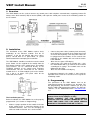
V1.00
Page 1/4
VBIP Install Manual
1. Overview
The VBIP Module can be used to connect any control panel, with telephone communicator, supporting Contact ID
format, to the local network (LAN) or internet (WAN), and report the control panel events to the monitoring station via
the IP network.
2. Installation
The installation of the VBIP Module requires basic
knowledge of the Ethernet network and the IP
protocols. If you do not familiar with these topics,
please, consult with an IT professional, or system
administrator before attempting the installation.
The VBIP Module should be installed next to the control
panel. Power can be supplied to the module from the
AUX power terminals of the control panel. The module
telco interface can be connected directly to the
TIP/RING terminals of the control panel telephone
communicator. For the connection to the ethernet
network there is an RJ45 modular jack on the module.
Use a Cat 5, or better, UTP patch cable for the
connection to the router.
•
•
Connect the power cable (2.54mm pitch connector)
to the AUX power terminals of the control panel and
check for correct polarity. Then the power cable can
be plugged on to the module. A few seconds after
powering up the module will start and the Status
LEDs will blink.
More Info: 4.1 Status LED display
Connect the UTP cable to the module jack – then
the VBIP Module will try to connect to the network
according to its settings. The network status can be
followed on the LEDs
More Info: 4.2 Network LED display
If programmed properly, the module is now ready for
operation and it sends its reset and test message to the
monitoring station.
3. Programming
The parameters of the VBIP Module have to be
programmed properly for problem free operation. For
the programming, the EniTerm software can be used
with the VBIP USB programming adapter. The EniTerm
software can be downloaded from www.villbau.com
free.
The installation process
Before installation, the VBIP Module has to be properly
programmed. (see. Section 3. Programming).
•
Choose a proper position for the module in the box
of the control panel. If connecting directly to the
TIP/RING terminals, take care for arranging the
cables to avoid mechanical stress to the module
ATTENTION!!! During programming the module is
powered from the PC USB port (5 VDC).
NEVER CONNECT THE USB PROGRAMMING
ADAPTER AND THE POWER CONNECTOR AT THE
SAME TIME! DOING THAT CAN CAUSE SERIOUS
DAMAGE TO THE MODULE AND/OR TO THE PC.
www.villbau.com
V1.00
Page 2/4
VBIP Install Manual
The following sections detail the network and telephone
communication parameters of the module.
3.1.
Network Parameters
These paramters define the operation of the VBIP
Module on the ethernet network.
IP Address
This is the IP address of the VBIP Module in case of
fixed IP addressing is chosen, and the module tries to
obtain this IP address first from the DHCP server. In
this case, however, it can occur, that the DHCP server
assigns another address to the module. The default IP
address is 192.168.1.128. Check the „Use DHCP”
switch to use automatic address inquiry.
Gateway/Router Address
The VBIP Modul forwards all requests to external IP
addresses to the gateway (router). The default is empty
(0.0.0.0), if using DHCP, the module obtains gateway
address from the router automatically.
Subnet Mask
The VBIP Module can decide between internal and
external addressing according to the given subnet
mask. The default is 255.255.255.0. with DHCP, the
module obtains subnet mask from the router
automatically.
Server IP Address
The VBIP Module tries to forward its events to this IP
address. The default is 192.168.1.240. In case the
server address is not known, the address resolution
through the name of the server is also possible:
Server Name
In case only the name of the server is known, the
module can resolve its IP address by using the DNS
name servers. DHCP must be enabled for this feature,
as the DNS server addresses are obtained from the
router. Also, the „Use DNS” switch must be enabled,
and the name of the server must be given. If the server
name is valid, the module will use its IP address for
forwarding events.
Server Port
The port of the monitoring server, where it receives the
events. By default it is 9999, the actual port is assigned
by the system administrator of the monitoring station.
VBIP Port
This is the port of the VBIP Modul, which is used for
reporting to the server. The default is 6200. This can be
any number, but care must be taken as specific port
numbers are already bound to functions according to
the standards (E.g. 21 for Telnet, 80 for HTTP, etc.)
UDP/TCP Reporting
For the VBIP Module it can be chosen, which protocol it
will use for reporting the events. The options are UDP
or TCP. Normally, UDP protocol uses a lower amount of
traffic, while in theory, TCP protocol offers extra data
security through its built-in software handshaking. In
practice, the UDP protocol ensures the proper data
security as well, with much less traffic, so that its usage
is recommended. Receiving servers usually support
both protocols, so that the final setting is decided by the
system administrator of the monitoring station. The
default setting is UDP.
IP Reporting Format
The VBIP Module supports multiple IP reporting
formats. The default is simple CID reporting, where the
Contact ID event is forwarded 1 to 1 as is, with or
without encryption (AES128 encryption is an option).
The second format is the E2, the custom IP format of
the Enigma II receiver. This allows forwarding additional
data as well, like MAC, Serial, etc. Encryption (AES128)
is also an option for this format. This format is of course
used primarily with Enigma II receivers.
The third optional format is the standard, SIA IP
reporting format (ANSI/SIA DC-09-2007), which offers
versatile use of the module with any monitoring station
supporting
this
standardized
format.
AES128
Encryption is optional for this format, too.
The actual reporting format to be used is always given
by the system adminsitrator of the monitoring station.
AES Encryption
Regardless of the reporting format used, the VBIP
Module can encrypt its messages (full or partial
encryption) with the AES-128 encryption method. This
is a standard encryption using a 128 bit key. The actuak
process (full or partial encryption) is determined by the
reporting format used. The key for the encryption is
provided by the system adminsitrator of the monitoring
station.
Keep Socket Open for Reporting
(not supported by version 1.00)
If using TCP protocol, the module closes the socket to
the server after succesful reporting. In some cases, it
might be useful to keep the socket open, even if there is
no event to report, thus maintaining continuous
connection to the server. This can be used for
monitoring the connection but care must be taken, as
maintaining too many open sockets at once, can
overload the monitoring station receiver. The usage of
this option is enabled by the system adminsitrator of the
monitoring station. By default, the option is disabled.
Note: In case the option is disabled, the module closes
the socket after about 10 seconds of inactivity. This
ensures, that the connection will not unnecessarily be
closed during telephone communication reception.
Block PING
The VBIP Module can block the incoming PING
commands, thus being „invisible” on the network. By
default, this option is disabled.
www.villbau.com
V1.00
Page 3/4
VBIP Install Manual
Telnet Server
The VBIP Module has a built-in Telnet server, which
can be used for remote access and management of the
module. If this option is enabled, the module will
respond to communication on the Port 21, and the user
can connect to it using a terminal application, program
parameters and query the event memory of the module.
By default, the access is disabled.
account ID, or with the module’s own account ID. (See
Account ID) The default setting is disabled.
Access via Telnet is password protected, the password
can be any string of upto 8 characters, and it can be
changed by the user if needed. The default access
password is 1234.
The setting of further communication parameters by the
user is not recommended, and should be performed
only if there is a communication problem with the
control panel. Please, consult with technical support
before setting these parameters.
HTTP Server, HTTP Port
In case it is enabled, the last 16 events log of the
module can be reviewed with a browser (http). For this
the HTTP server of the module has to be enabled. By
default, this function is disabled. The actual http port of
the module can be changed (default is 80) in case the
port is already assigned at the router. A suggested
alternative port address is 8080.
3.2.
Telco Parameters
The telephone communicator of the VBIP Module is a
simplified variant of the VBRC-4 telco, as it supports
DTMF Contact-ID communication only. Also. the
parameters are similar to the ones of the VBRC-4, and
they are as follow:
Single and Extended Modes
Using an external telephone line is not supported by the
VBIP Module by default. The module connects directly
to the TIP/RING terminals of the control panel, and
operates in line-simulation mode (Single Mode). With
the optional VBIP-XT card, the use of the external
telephone line is also possible, just like at the VBRC-4
communicator. To do this, the VBIP Module has to be
set to Extended Mode. More information about this topic
can be found in the VBIP-XT card installation manual.
Dial Tone
Some of the control panels require a dial tone before
calling out. The VBIP module can emit a standard,
continuous dial tone in line-simulation mode to
overcome this problem. By default, the dial tone is off.
3.3.
General Parameters
These parameters define the general operation of the
VBIP Module. The Accounts and Event Codes should
be negotiated with the system administrator of the
monitoring station.
Account ID
The VBIP Module has a 4 digit account ID, which is
used to forward its system messages. Also, the module
can be set to use this ID for all messages (See Use of
Own Account). The Account ID is given by the system
administrator of the monitoring station. The default is
„0001”
ContactID - Group ID
The module can use a specific Group ID for its
own/system events, so that they can be easily
differentiated from the events received from the control
panel. The default setting is „99”.
Event Codes
Most of the Contact ID event codes of the module’s own
events can be programmed. The defaults are selected
according to the most general usage.
Phone Number and Force Dial
This is the telephone number, which activates the VBIP
Module when dialled. Upon reception of this number,
the module will answer the call attempt, and tries to
receive events from the control panel. The option
„Force Dial” will force the module to anwer to any
numbers dialled while in line-simulation mode. The
default phone number is „9999”.
Test Parameters
The VBIP Module can generate periodic test events to
supervise the connection with the monitoring station.
The period of the test events can be programmed
between 1 minute and 127 hours. It is also possible to
send the value of the test period within the test event
message, at the zone ID position enabling the receiver
to supervise the tests. The default test period is 60
minutes.
Telephon Line Monitoring (TLM)
This option can be used only with the VBIP-XT card, as
it enables the monitoring of the external telephone line.
In case of line failure, the module will automatically
switch to line-simulation mode. This option is disabled
by default.
I/O Settings
Like the VBRC-4 communicator, the VBIP Module has
two programmable I/O channels. By default these are
inputs, with programmable sensitivty, and can be used
to monitor external events. The default sensitivity is
500ms.
Use of Own Account
At the VBIP Module it can be set, whether the received
messages should be forwarded with the received
Also, these I/O channels can be programmed as
outputs, in this case, the ouput functions are
programmable.
www.villbau.com
V1.00
Page 4/4
VBIP Install Manual
PGM Options
In case the I/Os are programmed as outputs, their
output functions can be programmed to follow module
status, or other events. These are set by the PGM
Options.
For both ports, the activating condition (module status
or event) can be programmed separately. This can be
combined with a second condition according to a
decision logic. Also, the operating mode of the output
(monostable, bistable or follow) and the timing of the
monostable mode can be set.
More info: see, 4.3 PGM Examples
4.3.
PGM Examples
The programming of the PGM outputs can be very
flexible. The following examples show solutions for
common situations.
4.3.1 Power failure indication (continuous)
Condition
inv
A-B relation
Mode
Time
Code
n
-
follow
---
---
A. PowerFail
4.3.2 3 Seconds impulse at line fault (w/ VBIP-XT card)
Condition
inv
A-B relation
Mode
Time
Code
n
-
trigger
003
---
A. LineFail
4.3.3 Follow port B status (negated)
4. Operation
Condition
inv
A-B relation
Mode
Time
Code
The operation and status of the VBIP Module is
displayed on the status and network LEDs as follows:
A. Input
y
-
follow
---
---
4.1.
Condition
inv
A-B relation
Mode
A. Code
n
-
trigger
Status LED Display
4.1.1. LED1
4.3.4 5 seconds impluse at given code (e.g. 1130)
Time
Code
005 1130
4.3.5 Input B will toggle Port A at Comm Fault
Program mode
Condition
inv
A-B relation
Mode
Time
Code
Programming in progress
A. Input
n
A and B
toggle
---
---
Ready, no external line
B. CommFail
n
---
---
---
---
Ready, external line present
4.3.6 Any of two events activate Port A for 30 sec.
(w/ VBIP-XT card only)
feltétel
inv
A-B reláció
üzemmód
Communication in progress
A. Code
n
A or B
trigger
Low Power Supply
B. Code
n
---
---
Idő
kód
030 1401
---
3401
4.1.2. LED2
This LED supports auxiliary information, e.g. signals the
reception during communication.
4.2.
Network LED Display
The activity of the ethernet interface of the module is
indicated by the LED3 and LED4, as follows:
LED3
LED4
off
off
slow
flash
fast
flash
on
slow
flash
fast
flash
on
off
off
TX/RX
flash
flash
flash
Description
No connection, the cable is not
plugged in.
IP address inquiry in progress
(DHCP)
Cannot resolve server IP
(DNS error, unknown server name)
Network is configured properly
LED4 shows network traffic
Problem on the local network
(LAN)
Problem with internet connection
(WAN)
Monitoring server is not found on
the network
5. Specifications
Technical specifications of the VBIP Modules
Power Supply
10.5 – 15.0 VDC
Max. Power Consumption
160 mA
Operating Temperature
0 – 50 °C
Ethernet Connection
10 Base-T
Size
48 mm x 42 mm x 15 mm
Weight
approx. 40 g
The VBIP Module conforms with the following EU
Standards: LVD 73/23/EEC (93/68/EEC), EMC
89/336/EEC (92/31/EEC, 93/68/EEC).
Security Classification according to EN50131-1:
Class II, Grade 3
VILLBAU Security Systems Ltd.
1182 Budapest, Üllői út 611., HUNGARY
Tel: (+36 1) 2975125, Fax: (+36 1) 2942928
www.villbau.com, e-mail: [email protected]
www.villbau.com