1
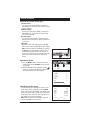
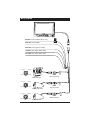
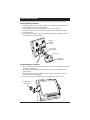
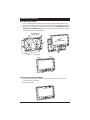
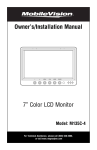
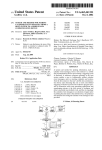
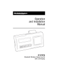
Owner’s/Installation Manual
7" Color LCD Monitor
Model: M125C
For Technical Assistance, please call (800) 638-3600,
or visit www.magnadyne.com
Table of Contents
Introduction . . . . . . . . . . . . . . . . . . . . . . . . . . . . . . . . . . . . . . . . . . . . . . . . . . . . . . . . . . . . . . . 2
Warning / Caution . . . . . . . . . . . . . . . . . . . . . . . . . . . . . . . . . . . . . . . . . . . . . . . . . . . . . . . . . . . 2
Monitor Features and Controls . . . . . . . . . . . . . . . . . . . . . . . . . . . . . . . . . . . . . . . . . . . . . . . . . 3
Remote Control Functions . . . . . . . . . . . . . . . . . . . . . . . . . . . . . . . . . . . . . . . . . . . . . . . . . . . . 4
General Operation . . . . . . . . . . . . . . . . . . . . . . . . . . . . . . . . . . . . . . . . . . . . . . . . . . . . . . . . . 4-6
Connection of Video Input Cable and Technical Specs . . . . . . . . . . . . . . . . . . . . . . . . . . . . . . . 7
Wiring Diagram . . . . . . . . . . . . . . . . . . . . . . . . . . . . . . . . . . . . . . . . . . . . . . . . . . . . . . . . . . . . 8
Installation Instructions . . . . . . . . . . . . . . . . . . . . . . . . . . . . . . . . . . . . . . . . . . . . . . . . . . . . 9-10
Maintenance . . . . . . . . . . . . . . . . . . . . . . . . . . . . . . . . . . . . . . . . . . . . . . . . . . . . . . . . . . . . . 11
Trouble Shooting . . . . . . . . . . . . . . . . . . . . . . . . . . . . . . . . . . . . . . . . . . . . . . . . . . . . . . . . . . 11
Warranty . . . . . . . . . . . . . . . . . . . . . . . . . . . . . . . . . . . . . . . . . . . . . . . . . . . . . . . . . . . . . . . . . 12
Introduction
Congratulations on the purchase of a quality MobileVision 7” LCD Monitor. This system has been
designed to provide years of trouble free operation.
The information enclosed provides a quick reference of the operations and maintenance of the
new monitor.
This product must be installed and used in accordance with this manual. Any alterations to this
product that enables it to be used in any way other than intended or designed could distract the
driver and result in an accident causing injury or death. Magnadyne Corporation disclaims any
and all liability that may result from failure to install and operate in any other manner in which
this was intended.
Warning
Backing Up Your Vehicle
Do not backup your vehicle while looking at the monitor. Always look in the direction of your
vehicle’s motion. Use the monitor only as an aid in safety confirmation. The actual distance
may be different than it appears in the monitor. The range of the image in the monitor is limited. Always be aware that blind spots may exist and not appear at all times on your monitor.
The product is intended to assist in safe driving and allows the driver to have a broader field
of vision during backup. You, as the driver, are solely responsible for the safe operation of
your vehicle and the safety of your passengers and pedestrians, and for abiding of all state
and local traffic regulations. Do not use any features of this system to the extent it distracts
you from safe driving. Your first priority while driving should always be the safe operation
of your vehicle. MobileVision will not accept any responsibility whatsoever for accidents
and/or injuries resulting from failure to observe these precautions or safety instructions.
Caution
• FCC REGULATIONS STATE THAT ANY UNAUTHORIZED CHANGES OR MODIFICATIONS TO THIS EQUIPMENT MAY VOID THE USER’S AUTHORITY TO OPERATE IT.
• TO REDUCE THE RISK OF FIRE OR ELECTRIC SHOCK, DO NOT EXPOSE THIS EQUIPMENT TO RAIN OR
MOISTURE.
• THIS DEVICE IS INTENDED FOR CONTINUOUS OPERATION.
• TO REDUCE THE RISK OF FIRE OR ELECTRIC SHOCK AND ANNOYING INTERFERENCE, USE ONLY THE
RECOMMENDED ACCESSORIES.
2
Monitor Features and Controls
1
2
3
4
5
6
1. LCD Screen
2. IR Sensor: Receives signal from the
remote control.
3. LED Power Indicator:
A red LED indicates the vehicle’s ignition
is “On” and the monitor is in the “standby” mode. When the vehicle is put into
reverse or the turn signals are used the
camera’s image will automatically appear
on the display. Note: The cameras can
not be manually selected in this mode.
A green LED indicates the power button
on the monitor has been pressed and the
ignition is “On”. The camera’s images
can manually be selected to appear by
using the SEL button. The video in jack
is also operational.
LED is off: The monitor has no function.
4. Power Button: Press this button to turn
the unit "On" or "Off".
Note: The ignition key must be in the
“On” position.
5. Brightness Button (Decrease): Press
this button to decrease the screen’s
brightness.
Note: When the menu is displayed press
this button to adjust the selected menu
item.
7
8
9
10
11
6. Brightness Button (Increase): Press this
button to increase the screen’s brightness.
Note: When the menu is displayed, press
this button to adjust the selected menu
item.
7. CH- Button (Menu Item Selection):
Press this button to select a menu item
when a menu is displayed.
8. Menu Button: Press this button to select
a desired menu screen.
9. SEL: Press this button to select a video
sources (CAM1, CAM2, CAM3 and DVD).
Note 1: When the left turn signal is activated CAM1 (left side view camera) is
selected automatically.
Note 2: When the right turn signal is
activated CAM2 (right side view camera)
is selected automatically.
Note 3: When the vehicle is put into
reverse CAM3 (rearview camera) is
selected automatically.
10. Video Input Jack
11. Speaker: The speaker is automatically
activated only when the vehicle is put
into reverse.
Note: The rear camera must have a builtin microphone for proper operation.
3
Remote Control Functions
1
MUTE
POWER
7
8
2
CH
3
MENU
CH
4
9
5
MODE
CALL
TIMER
6
LANG
SYS
SEL
10
11
12
1. Mute: Push to "Mute" the volume.
2.
: Press this button to select between
a Mirror or Normal screen image.
: Press this button to flip the screen
image vertically.
3. POWER: Press this button to turn the
unit "On" or "Off".
4. MENU: Press this button to select a
desired menu.
5. MODE (Picture Mode): Press to select
between Personal, Standard, Soft, Vivid
and Light picture settings.
6. LANG (Language Mode): Press to select
display language.
7. POWER: Press this button to turn the
unit "On" or "Off".
8. CH
: Press these buttons to scroll
through a menu Up or Down.
9. CALL: Press to close the menu.
10. TIMER: Press to select the shut off time.
When the timer expires the monitor will
automatically shut off.
11. SEL: Press this button to select a video
sources (CAM1, CAM2, CAM3 and DVD).
Note 1: When the left turn signal is activated CAM1 (left side view camera) is
selected automatically.
Note 2: When the right turn signal is
activated CAM2 (right side view camera)
is selected automatically.
Note 3: When the vehicle is put into
reverse CAM3 (rearview camera) is
selected automatically.
12. SYS: Press to select PAL, AUTO, N443
or N358.
General Operation
Turning the Monitor On:
The monitor is operational by activating the ignition
key then manually pressing the power switch on the
unit.
Adjusting the Brightness
Press the
buttons on the monitor to adjust the
brightness of the monitor.
Brightness Brightness
Up
Down
4
General Operation
Camera View Selection and A/V Input:
Left Side Camera:
The left side view camera (CAM1) is designed to
automatically turn on whenever the vehicle’s left turn
signal is activated.
Right Side Camera:
The right side view camera (CAM2) is designed to
automatically turn on whenever the vehicle’s right
turn signal is activated.
Rearview Camera:
The rearview camera (CAM3) is designed to automatically turn on whenever the vehicle is placed into
reverse gear.
Video Input:
Manually select the video input by pressing the SEL
button on the monitor until DVD appears in the display.
Note: Select any camera view manually by pressing
the SEL button on the monitor. If a camera view is
automatically activated (Example: the vehicle is in
reverse) you will not be able to manually select a different camera view until the vehicle taken out of
reverse.
Adjusting the Volume
1. Press the MENU button on either the monitor or
remote control and the PICTURE menu screen will
be displayed.
2. With the VOLUME feature highlighted, use the
buttons on the monitor to adjust the volume. Wait
15 seconds and the menu will disappear.
2.
1.
Volume Volume
Up
Down
PICTURE
VOLUME
BRIGHT
CONTRAST
COLOR
SHARP
HUE
SELECT
Mirror/Normal Camera Image:
The camera image can be displayed as normal or mirror
image. Adjust a specific camera by pressing the MENU
button on the monitor until “OPTION” menu appears in the
display. Follow the instruction on the screen to change the
camera image. After selection has been made wait 15 seconds and the menu screen will disappear.
Note: CAM1 is left side camera, CAM2 is right side
camera and CAM3 is rearview camera.
35
40
50
50
50
50
35
ADJUST
OPTION
LANG
SCALE
CAM1
CAM2
CAM3
DVD
SELECT
ENG
OFF
MIRROR
NORMAL
NORMAL
NORMAL
ADJUST
5
General Operation (continued)
Monitor Adjustment
The monitor has three basic menus: Picture, Option and System. To scroll through the three
basic menus continuously press the MENU button.
Picture Menu
Press the Menu button on either the monitor front
panel or remote control until the PICTURE menu
screen is displayed. Use the
buttons on the
remote to scroll through the menu items and select
from the menu items: VOLUME, BRIGHT, CONTRAST,
COLOR, SHARP and HUE. Then use the
buttons to make adjustments to the selected item.
Note: NTSC color system will display “HUE”, but PAL
will not.
Option Menu
Press the Menu button on either the monitor front
panel or remote control until the OPTION menu
screen is displayed. Use the
buttons on the
remote to scroll through the menu and select from
the menu items: LANG, SCALE, CAM1, CAM2, CAM3
and DVD. Then use the
buttons to make adjustments to the selected item.
Note: If SCALE is selected “ON” then the monitor will
display a distance grid when the reverse camera is
selected. The grid is a reference point and can not be
used as an accurate measurement.
PICTURE
VOLUME
BRIGHT
CONTRAST
COLOR
SHARP
HUE
SELECT
35
40
50
50
50
50
35
ADJUST
OPTION
LANG
SCALE
CAM1
CAM2
CAM3
DVD
SELECT
ENG
OFF
NORMAL
NORMAL
NORMAL
NORMAL
ADJUST
System Menu
Press the Menu button on either the monitor front
panel or remote control until the SYSTEM menu
screen is displayed. Use the
buttons on the
remote to scroll through the menu and select from the
menu items: COLOR-SYS, BLUE BLACK, HORIZONTAL, VERTICAL and ZOOM. Then use the
buttons to make adjustments to the selected item.
SYSTEM
COLOR-SYS
BLUE BLACK
HORIZONTAL
VERTICAL
ZOOM
SELECT
6
ADJUST
AUTO
OFF
0
Front Panel Video Input
Yellow RCA: Video (Cable Not Supplied)
Auxiliary Video Input
You can connect the video output signal of a digital
camera, camcorder or video device. Select the auxiliary
video input mode by pressing the SEL button on the
monitor until DVD appears in the display.
Cable Suggestions: Radio Shack #42-2551 or #42-2483.
Technical Specifications
• 7” TFT-LCD color monitor
• Audio output: 1 watt
• Front speaker
• Power supply: automobile storage battery (12-32V)
• Power consumption: about 10 watts
• Outer dimension: 182mm (W) x 122mm (H) x 26mm (D) without flush mount
198mm (W) x 138mm (H) x 31mm (D) with flush mount
• Dot pitch: 0.321 (W) x 0.372 (H)
• Resolution: 480 x 3 (RGB) x 234
• Contrast: 250:1
• Brightness: 450cd/m2
• Viewing angle: U: 30 / D: 60, R/L: 60
• Operating temperature: -20 ~ +70O C, RH90%
• Storage temperature: -30 ~ +80O C, RH90%
7
Wiring Diagram
Red Wire: 12 Volt Switched (DC 12~32V)
Black Wire: Ground (GND)
2 Amp
White Wire: Left Trigger (LEFT TRIG)
Gray Wire: Right Trigger (RIGHT TRIG)
Green Wire: Rear Trigger (REAR TRIG)
5. Ground
REAR TRIG
1. +12 Volts
2. N/A
4. Video
3. Audio
C125 (Rearview)
3. N/A
1. +12 Volts
2. N/A
C-SDR (Right Side)
5. Ground
CAM1
(White Connector)
4. Video
3. N/A
8
CAM2
(Gray Connector)
4. Video
LEFT TRIG
2. N/A
5. Ground
RIGHT TRIG
1. +12 Volts
CAM3
(Green Connector)
C-SDL (Left Side)
Installation Instructions
The monitor can be mounted via a pedestal-mount, U-support bracket or a flush-mount.
Pedestal Mounting the Monitor
1. Loosen the thumb wheel on the base support so the nut attached to the thumb wheel
can slide into the monitor’s mounting channel.
2. Slide the thumb wheel nut into the channel on the back of the monitor.
3. Position the monitor to the desired height and tighten the base support thumb wheel.
4. Adjust the tilt lever.
5. Use the double-sided foam (supplied) or mounting screws (not supplied) to secure the
base support to the desired location.
Monitorís
Mounting
Channel
Base Support
Thumb Screw
Tilt Lever
Nut
Double Sided
Mounting Foam
U-Support Mounting the Monitor
1. Select a position to mount the monitor that is free of obstructions and moving parts and
has a proper viewing angle.
2. Remove the mounting bracket from the monitor and use it as a template to drill the
mounting holes.
3. Position the monitor mounting bracket and align with pre-drilled holes, then secure
bracket with screws (not supplied).
4. Secure the monitor to the mounting bracket using adjustment thumb screws.
Angle Adjustment
Thumb Screw
CH-
MENU
SEL
POWER
9
Installation Instructions
Flush Mounting the Monitor
1. Locate a suitable location for mounting the monitor (In-Dash, In-Wall, Headrest, etc.).
Then cut a 7-1/8" (W) x 4-7/8" (H) opening and insert and secure the flush-mount housing.
2. After securing the housing, insert the monitor into the housing. Do Not Apply Pressure
Directly to the LCD Monitor’s Screen. Utilize the outer edges to gently push the monitor
into the housing until it snaps into place.
Mounting Screws
(Not Supplied)
Do Not
creen
Press on S
Cut a 7 3/8" x 5" Opening
“Snap”
“Snap”
“Snap”
“Snap”
Removing the Flush Mounted Monitor
1. Insert the detaching piece as indicated. Press in and lift up and the monitor will be
released from the flush mount.
2. Remove the monitor.
10
Maintenance
Although this monitor requires little care, you can still maintain its condition and performance
by following these steps:
• Keep the system away from excessive moisture, extreme heat or cold, and magnetic fields.
• Occasionally clean the monitor screen with damp soft cloth.
Should you experience any problem with the system please refer to the troubleshooting guide
prior to returning your system for repair.
Note 1: The user should not attempt to service the unit beyond that described in the operating
instructions. All other servicing should be referred to qualified personnel.
Note 2: Do not expose the unit to water or excessive moisture. This could cause electrical
shorts, fire or other damage.
Troubleshooting
Only qualified personnel should remove the cover or service this unit. The warranty will become invalid
if factory security seal is broken.
Symptoms
Solutions
Unstable Image
• Low-Voltage – Check Battery
• Check Generator
• If the systems is wireless move vehicle to
another location, as the problem may be
caused by outside interference.
Cloudy Image
• Clean Dirty Camera Lens
• Clean Dirty Monitor Lens
• Adjust Contrast
• Adjust Brightness
No Power/Picture
• Check Fuses
• Check if AV Cable is Properly Connected
to Monitor
No Sound
• Check Volume Level and Audio
Connection
Note: The speaker is only operational when
the vehicle is put into reverse and is automatically activated.
No Color
• Check Color Level Settings
Upside Down or Inverted Image
• Check Horizontal and Vertical Settings
Monitor Does Not Display Image When
Vehicle is in Reverse
• Check the Green Reverse Trigger Wire for
Proper 12 Volt Connection.
• Check Video Inputs to Ensure they are
Properly Connected
11
Warranty
ONE (1) YEAR LIMITED WARRANTY
Magnadyne Corporation or its authorized agents will within one year from the date of sale
to you, repair, replace or refund the retail sales price of said product or any part thereof, at
the option of the Magnadyne Corporation or its authorized agents, if said product or part
is found defective in materials or workmanship, when properly connected and operating on
the correct power requirements designated for the specific product. This warranty and
Magnadyne Corporation or its authorized agent’s obligations hereunder do not apply where
the product was; damaged while in the possession of the consumer, subjected to unreasonable or unintended use, not reasonably maintained, utilized in commercial or industrial
operations, or serviced by anyone other than Magnadyne Corporation or its authorized
agents, or where the warning seal on the product is broken or the power and/or plugs are
detached from the unit. Magnadyne Corporation or any of its authorized agents will not
assume any labor costs for the removal and reinstallation of any product found to be defective, or the cost of transportation to Magnadyne Corporation or its authorized agents. Such
cost are the sole responsibility of the purchaser.
This warranty does not cover the cabinet appearance items or accessories used in connection with this product, or any damage to recording or recording tape, or any damage to
the products resulting from improper installation, alteration, accident, misuse, abuse or
acts of nature.
MAGNADYNE CORPORATION OR ITS AUTHORIZED AGENTS SHALL NOT BE LIABLE TO
ANYONE FOR CONSEQUENTIAL OR INCIDENTAL DAMAGES OR CLAIMS EXCEPT THOSE
ACCORDED BY LAW. NO EXPRESSED WARRANTY OR IMPLIED WARRANTY IS GIVEN
EXCEPT THOSE SET FORTH HEREIN. NO IMPLIED WARRANTY SHALL EXTEND BEYOND
ONE YEAR FROM THE DATE OF SALE.
This warranty extends only to the original purchaser of the product and is not
transferable. Some states do not allow limitations on how long an implied warranty lasts,
and some states do not allow the exclusion or limitation of incidental or consequential
damages, so the above limitations or exclusion may not apply to you. This warranty gives
you specific legal rights, and you may have other rights that vary from state to state.
“NOTE: The manufacturer is not responsible for any radio or TV interference caused by
unauthorized modifications to this equipment. Such modifications could void the User’s
authority to operate the equipment.”
Defective merchandise should be returned to the original point of purchase or
secondly, to Magnadyne Corporation, 1111 W. Victoria Street, Compton CA 90220.
Return Authorization must be obtained before sending, or merchandise may be refused.
Copyright © 2008 MobileVision
M125C-UM Rev. A 3-10-08