1
Agilent 75000 SERIES C
Agilent E1445A
Arbitrary Function Generator
Service Manual
Serial Numbers
This manual applies directly to instruments with serial numbers
prefixed with 3144A.
Copyright© Agilent Technologies, Inc. 1992-2005
Manual Part Number: E1445-90011
Printed: November 2005 Edition 2
Printed in U.S.A. E1105
Contents
Chapter 1 - General Information
Introduction . . . . . . . . . .
Safety Considerations . . . . .
Warnings and Cautions . .
Inspection/Shipping . . . . . .
Initial Inspection . . . . . .
Shipping Guidelines . . . .
Environment . . . . . . . . . .
AFG Description . . . . . . .
AFG Specifications . . . .
AFG Options . . . . . . . .
AFG Serial Numbers . . .
Recommended Test Equipment
.
.
.
.
.
.
.
.
.
.
.
.
.
.
.
.
.
.
.
.
.
.
.
.
.
.
.
.
.
.
.
.
.
.
.
.
.
.
.
.
.
.
.
.
.
.
.
.
.
.
.
.
.
.
.
.
.
.
.
.
.
.
.
.
.
.
.
.
.
.
.
.
.
.
.
.
.
.
.
.
.
.
.
.
.
.
.
.
.
.
.
.
.
.
.
.
.
.
.
.
.
.
.
.
.
.
.
.
.
.
.
.
.
.
.
.
.
.
.
.
.
.
.
.
.
.
.
.
.
.
.
.
.
.
.
.
.
.
.
.
.
.
.
.
.
.
.
.
.
.
.
.
.
.
.
.
.
.
.
.
.
.
.
.
.
.
.
.
.
.
.
.
.
.
.
.
.
.
.
.
.
.
.
.
.
.
.
.
.
.
.
.
.
.
.
.
.
.
.
.
.
.
.
.
.
.
.
.
.
.
.
.
.
.
.
.
.
.
.
.
.
.
.
.
.
.
.
.
.
.
.
.
.
.
.
.
.
.
.
.
.
.
.
.
.
.
.
.
.
.
.
.
.
.
.
.
.
.
.
.
.
.
.
.
.
.
.
.
.
.
.
.
.
.
.
.
.
.
.
.
.
.
.
.
.
.
.
.
.
.
.
.
.
.
.
.
.
.
.
.
.
.
.
.
.
.
.
.
.
.
.
.
.
.
.
.
.
.
.
.
.
.
.
.
.
.
.
.
.
.
.
.
.
.
.
.
.
.
.
.
.
.
.
.
.
.
.
.
.
.
.
.
.
.
.
.
.
.
.
.
9
10
10
12
12
13
14
14
14
14
14
15
Introduction . . . . . . . . . . . . . . . . . . . .
Test Conditions/Procedures . . . . . . . . . .
Performance Test Record . . . . . . . . . . .
Verification Test Examples . . . . . . . . . .
Command Coupling . . . . . . . . . . . . . .
Functional Verification . . . . . . . . . . . . . .
Self-Test . . . . . . . . . . . . . . . . . . . .
Ref In/Marker Out Test . . . . . . . . . . . .
Start Arm In Test . . . . . . . . . . . . . . .
Start Arm In Test (cont’d) . . . . . . . . . . .
Gate In Test . . . . . . . . . . . . . . . . . .
Output Relay Test . . . . . . . . . . . . . . .
Operation Verification . . . . . . . . . . . . . .
Performance Verification . . . . . . . . . . . . .
Test 2-1: DC Zeros . . . . . . . . . . . . . .
Test 2-2: DC Accuracy . . . . . . . . . . . .
Test 2-3: DC Offset . . . . . . . . . . . . . .
Test 2-4: AC Accuracy . . . . . . . . . . . .
Test 2-5: AC Flatness - 250 kHz Filter . . . .
Test 2-6: AC Flatness - 10 MHz Filter . . . .
Test 2-7: Frequency Accuracy . . . . . . . .
Test 2-8: Duty Cycle . . . . . . . . . . . . .
Test 2-9: Total Harmonic Distortion . . . . .
Test 2-10: Spurious/Non-Harmonic Distortion
Performance Test Record . . . . . . . . . . . . .
AFG Test Limits . . . . . . . . . . . . . . . .
Measurement Uncertainty . . . . . . . . . . .
Test Accuracy Ratio (TAR) . . . . . . . . . .
.
.
.
.
.
.
.
.
.
.
.
.
.
.
.
.
.
.
.
.
.
.
.
.
.
.
.
.
.
.
.
.
.
.
.
.
.
.
.
.
.
.
.
.
.
.
.
.
.
.
.
.
.
.
.
.
.
.
.
.
.
.
.
.
.
.
.
.
.
.
.
.
.
.
.
.
.
.
.
.
.
.
.
.
.
.
.
.
.
.
.
.
.
.
.
.
.
.
.
.
.
.
.
.
.
.
.
.
.
.
.
.
.
.
.
.
.
.
.
.
.
.
.
.
.
.
.
.
.
.
.
.
.
.
.
.
.
.
.
.
.
.
.
.
.
.
.
.
.
.
.
.
.
.
.
.
.
.
.
.
.
.
.
.
.
.
.
.
.
.
.
.
.
.
.
.
.
.
.
.
.
.
.
.
.
.
.
.
.
.
.
.
.
.
.
.
.
.
.
.
.
.
.
.
.
.
.
.
.
.
.
.
.
.
.
.
.
.
.
.
.
.
.
.
.
.
.
.
.
.
.
.
.
.
.
.
.
.
.
.
.
.
.
.
.
.
.
.
.
.
.
.
.
.
.
.
.
.
.
.
.
.
.
.
.
.
.
.
.
.
.
.
.
.
.
.
.
.
.
.
.
.
.
.
.
.
.
.
.
.
.
.
.
.
.
.
.
.
.
.
.
.
.
.
.
.
.
.
.
.
.
.
.
.
.
.
.
.
.
.
.
.
.
.
.
.
.
.
.
.
.
.
.
.
.
.
.
.
.
.
.
.
.
.
.
.
.
.
.
.
.
.
.
.
.
.
.
.
.
.
.
.
.
.
.
.
.
.
.
.
.
.
.
.
.
.
.
.
.
.
.
.
.
.
.
.
.
.
.
.
.
.
.
.
.
.
.
.
.
.
.
.
.
.
.
.
.
.
.
.
.
.
.
.
.
.
.
.
.
.
.
.
.
.
.
.
.
.
.
.
.
.
.
.
.
.
.
.
.
.
.
.
.
.
.
.
.
.
.
.
.
.
.
.
.
.
.
.
.
.
.
.
.
.
.
.
.
.
.
.
.
.
.
.
.
.
.
.
.
.
.
.
.
.
.
.
.
.
.
.
.
.
.
.
.
.
.
.
.
.
.
.
.
.
.
.
.
.
.
.
.
.
.
.
.
.
.
.
.
.
.
.
.
.
.
.
.
.
.
.
.
.
.
.
.
.
.
.
.
.
.
.
.
.
.
.
.
.
.
.
.
.
.
.
.
.
.
.
.
.
17
17
17
17
18
18
19
20
21
22
23
25
32
32
33
38
41
45
49
52
56
60
64
69
73
73
73
74
Chapter 2 - Verification Tests
Agilent E1445A Service Manual
Contents
1
Chapter 3 - Adjustments
Introduction . . . . . . . . . . . . . . . . . . . . .
Required Equipment . . . . . . . . . . . . . . .
Recommended Environment . . . . . . . . . .
Calibration Commands . . . . . . . . . . . . . . .
Defeating Calibration Security . . . . . . . . . . .
DC Adjustment Procedure . . . . . . . . . . . . .
AC Flatness Adjustment Procedure - 250 kHz Filter
AC Flatness Adjustment Procedure - 10 MHz Filter
Skew DAC Adjustment Procedure . . . . . . . . .
.
.
.
.
.
.
.
.
.
.
.
.
.
.
.
.
.
.
.
.
.
.
.
.
.
.
.
.
.
.
.
.
.
.
.
.
.
.
.
.
.
.
.
.
.
.
.
.
.
.
.
.
.
.
.
.
.
.
.
.
.
.
.
.
.
.
.
.
.
.
.
.
.
.
.
.
.
.
.
.
.
.
.
.
.
.
.
.
.
.
.
.
.
.
.
.
.
.
.
.
.
.
.
.
.
.
.
.
.
.
.
.
.
.
.
.
.
.
.
.
.
.
.
.
.
.
.
.
.
.
.
.
.
.
.
.
.
.
.
.
.
.
.
.
.
.
.
.
.
.
.
.
.
.
.
.
.
.
.
.
.
.
.
.
.
.
.
.
.
.
.
83
83
83
83
86
87
93
94
109
117
117
117
117
Chapter 4 - Replaceable Parts
Introduction . . . . . . .
Exchange Assemblies
Ordering Information
Replaceable Parts List . .
.
.
.
.
.
.
.
.
.
.
.
.
.
.
.
.
.
.
.
.
.
.
.
.
.
.
.
.
.
.
.
.
.
.
.
.
.
.
.
.
.
.
.
.
.
.
.
.
.
.
.
.
.
.
.
.
.
.
.
.
.
.
.
.
.
.
.
.
.
.
.
.
.
.
.
.
.
.
.
.
.
.
.
.
.
.
.
.
.
.
.
.
.
.
.
.
.
.
.
.
.
.
.
.
.
.
.
.
.
.
.
.
.
.
.
.
.
.
.
.
.
.
.
.
.
.
.
.
.
.
.
.
Introduction . . . . . . . . . . . . .
Equipment Required . . . . . . .
Service Aids . . . . . . . . . . .
Troubleshooting Techniques . . . .
Identifying the Problem . . . . .
Testing the Assembly . . . . . .
Disassembly . . . . . . . . . . .
Removing BNC Connectors . . .
Repair/Maintenance Guidelines . .
ESD Precautions . . . . . . . . .
Soldering Printed Circuit Boards
Post-Repair Safety Checks . . .
.
.
.
.
.
.
.
.
.
.
.
.
.
.
.
.
.
.
.
.
.
.
.
.
.
.
.
.
.
.
.
.
.
.
.
.
.
.
.
.
.
.
.
.
.
.
.
.
.
.
.
.
.
.
.
.
.
.
.
.
.
.
.
.
.
.
.
.
.
.
.
.
.
.
.
.
.
.
.
.
.
.
.
.
.
.
.
.
.
.
.
.
.
.
.
.
.
.
.
.
.
.
.
.
.
.
.
.
.
.
.
.
.
.
.
.
.
.
.
.
.
.
.
.
.
.
.
.
.
.
.
.
.
.
.
.
.
.
.
.
.
.
.
.
.
.
.
.
.
.
.
.
.
.
.
.
.
.
.
.
.
.
.
.
.
.
.
.
.
.
.
.
.
.
.
.
.
.
.
.
.
.
.
.
.
.
.
.
.
.
.
.
.
.
.
.
.
.
.
.
.
.
.
.
.
.
.
.
.
.
.
.
.
.
.
.
.
.
.
.
.
.
.
.
.
.
.
.
.
.
.
.
.
.
.
.
.
.
.
.
.
.
.
.
.
.
.
.
.
.
.
.
.
.
.
.
.
.
.
.
.
.
.
.
.
.
.
.
.
.
.
.
.
.
.
.
.
.
.
.
.
.
.
.
.
.
.
.
.
.
.
.
.
.
.
.
.
.
.
.
.
.
.
.
.
.
.
.
.
.
.
.
. 121
. 121
. 121
. 122
. 122
. 122
. 123
. 124
. 125
. 125
. 125
. 125
Chapter 5 - Service
2
Contents
Agilent E1445A Service Manual
Certification
Agilent Technologies certifies that this product met its published specifications at the time of shipment from the factory. Agilent Technologies further certifies that its calibration measurements are traceable to the United States National Institute of Standards and Technology (formerly National Bureau of Standards), to the extent allowed by that organization’s calibration facility, and to the calibration
facilities of other International Standards Organization members.
Warranty
This Agilent Technologies product is warranted against defects in materials and workmanship for a period of three years from date of
shipment. Duration and conditions of warranty for this product may be superseded when the product is integrated into (becomes a part
of) other Agilent products. During the warranty period, Agilent Technologies will, at its option, either repair or replace products which
prove to be defective.
For warranty service or repair, this product must be returned to a service facility designated by Agilent Technologies. Buyer shall prepay shipping charges to Agilent and Agilent shall pay shipping charges to return the product to Buyer. However, Buyer shall pay all
shipping charges, duties, and taxes for products returned to Agilent from another country.
Agilent warrants that its software and firmware designated by Agilent for use with a product will execute its programming instructions
when properly installed on that product. Agilent does not warrant that the operation of the product, or software, or firmware will be uninterrupted or error free.
Limitation Of Warranty
The foregoing warranty shall not apply to defects resulting from improper or inadequate maintenance by Buyer, Buyer-supplied products or interfacing, unauthorized modification or misuse, operation outside of the environmental specifications for the product, or improper site preparation or maintenance.
The design and implementation of any circuit on this product is the sole responsibility of the Buyer. Agilent does not warrant the
Buyer’s circuitry or malfunctions of Agilent products that result from the Buyer’s circuitry. In addition, Agilent does not warrant any
damage that occurs as a result of the Buyer’s circuit or any defects that result from Buyer-supplied products.
NO OTHER WARRANTY IS EXPRESSED OR IMPLIED. Agilent SPECIFICALLY DISCLAIMS THE IMPLIED WARRANTIES
OF MERCHANTABILITY AND FITNESS FOR A PARTICULAR PURPOSE.
Exclusive Remedies
THE REMEDIES PROVIDED HEREIN ARE BUYER’S SOLE AND EXCLUSIVE REMEDIES. Agilent SHALL NOT BE LIABLE
FOR ANY DIRECT, INDIRECT, SPECIAL, INCIDENTAL, OR CONSEQUENTIAL DAMAGES, WHETHER BASED ON CONTRACT, TORT, OR ANY OTHER LEGAL THEORY.
Notice
The information contained in this document is subject to change without notice. Agilent Technologies MAKES NO WARRANTY OF
ANY KIND WITH REGARD TO THIS MATERIAL, INCLUDING, BUT NOT LIMITED TO, THE IMPLIED WARRANTIES OF
MERCHANTABILITY AND FITNESS FOR A PARTICULAR PURPOSE. Agilent shall not be liable for errors contained herein or
for incidental or consequential damages in connection with the furnishing, performance or use of this material. This document contains
proprietary information which is protected by copyright. All rights are reserved. No part of this document may be photocopied, reproduced, or translated to another language without the prior written consent of Agilent Technologies, Inc. Agilent assumes no responsibility for the use or reliability of its software on equipment that is not furnished by Agilent.
U.S. Government Restricted Rights
The Software and Documentation have been developed entirely at private expense. They are delivered and licensed as "commercial
computer software" as defined in DFARS 252.227- 7013 (Oct 1988), DFARS 252.211-7015 (May 1991) or DFARS 252.227-7014 (Jun
1995), as a "commercial item" as defined in FAR 2.101(a), or as "Restricted computer software" as defined in FAR 52.227-19 (Jun
1987)(or any equivalent agency regulation or contract clause), whichever is applicable. You have only those rights provided for such
Software and Documentation by the applicable FAR or DFARS clause or the Agilent standard software agreement for the product involved.
Agilent E1445A Arbitrary Function Generator Service Manual
Edition 2
Copyright © 1992-2005 Agilent Technologies, Inc. All Rights Reserved.
Agilent E1445A Service Manual
3
Printing History
The Printing History shown below lists all Editions and Updates of this manual and the printing date(s). The first printing of the manual is Edition 1. The Edition number increments by 1 whenever the manual is revised. Updates, which are issued between Editions,
contain replacement pages to correct the current Edition of the manual. Updates are numbered sequentially starting with Update 1.
When a new Edition is created, it contains all the Update information for the previous Edition. Each new Edition or Update also includes a revised copy of this printing history page. Many product updates or revisions do not require manual changes and, conversely,
manual corrections may be done without accompanying product changes. Therefore, do not expect a one-to-one correspondence between product updates and manual updates.
Edition 1 (Part Number E1445-90010). . . . . . . . . . . . . . . . . . . . September 1992
Edition 2 (Part Number E1445-90011). . . . . . . . . . . . . . . . . . . . September 1996
Safety Symbols
Instruction manual symbol affixed to product. Indicates that the user must refer to the
manual for specific WARNING or CAUTION information to avoid personal injury
or damage to the product.
Alternating current (AC).
Direct current (DC).
Indicates hazardous voltages.
Indicates the field wiring terminal that must
be connected to earth ground before operating the equipment—protects against electrical shock in case of fault.
or
Frame or chassis ground terminal—typically connects to the equipment’s metal
frame.
WARNING
Calls attention to a procedure, practice, or
condition that could cause bodily injury or
death.
CAUTION
Calls attention to a procedure, practice, or condition that could possibly cause damage to
equipment or permanent loss of data.
WARNINGS
The following general safety precautions must be observed during all phases of operation, service, and repair of this product.
Failure to comply with these precautions or with specific warnings elsewhere in this manual violates safety standards of design,
manufacture, and intended use of the product. Agilent Technologies assumes no liability for the customer’s failure to comply
with these requirements.
Ground the equipment: For Safety Class 1 equipment (equipment having a protective earth terminal), an uninterruptible safety earth
ground must be provided from the mains power source to the product input wiring terminals or supplied power cable.
DO NOT operate the product in an explosive atmosphere or in the presence of flammable gases or fumes.
For continued protection against fire, replace the line fuse(s) only with fuse(s) of the same voltage and current rating and type.
DO NOT use repaired fuses or short-circuited fuse holders.
Keep away from live circuits: Operating personnel must not remove equipment covers or shields. Procedures involving the removal
of covers or shields are for use by service-trained personnel only. Under certain conditions, dangerous voltages may exist even with the
equipment switched off. To avoid dangerous electrical shock, DO NOT perform procedures involving cover or shield removal unless
you are qualified to do so.
DO NOT operate damaged equipment: Whenever it is possible that the safety protection features built into this product have been impaired, either through physical damage, excessive moisture, or any other reason, REMOVE POWER and do not use the product until
safe operation can be verified by service-trained personnel. If necessary, return the product to an Agilent Technologies Sales and Service Office for service and repair to ensure that safety features are maintained.
DO NOT service or adjust alone: Do not attempt internal service or adjustment unless another person, capable of rendering first aid
and resuscitation, is present.
DO NOT substitute parts or modify equipment: Because of the danger of introducing additional hazards, do not install substitute
parts or perform any unauthorized modification to the product. Return the product to an Agilent Technologies Sales and Service Office
for service and repair to ensure that safety features are maintained.
4
Agilent E1445A Service Manual
DECLARATION OF CONFORMITY
According to ISO/IEC Guide 22 and CEN/CENELEC EN 45014
Manufacturer’s Name:
Manufacturer’s Address:
Agilent Technologies, Incorporated
th
815 – 14 St. SW
Loveland, Colorado 80537
USA
Declares, that the product
Product Name:
Model Number:
Product Options:
Arbitrary Function Generator
E1445A
This declaration covers all options of the above product(s).
Conforms with the following European Directives:
The product herewith complies with the requirements of the Low Voltage Directive 73/23/EEC and the EMC Directive 89/336/EEC
(including 93/68/EEC) and carries the CE Marking accordingly.
Conforms with the following product standards:
EMC
Standard
Limit
IEC 61326-1:1997+A1:1998 / EN 61326-1:1997+A1:1998
CISPR 11:1990 / EN 55011:1991
IEC 61000-4-2:1995+A1:1998 / EN 61000-4-2:1995
IEC 61000-4-3:1995 / EN 61000-4-3:1995
IEC 61000-4-4:1995 / EN 61000-4-4:1995
IEC 61000-4-5:1995 / EN 61000-4-5:1995
IEC 61000-4-6:1996 / EN 61000-4-6:1996
IEC 61000-4-11:1994 / EN 61000-4-11:1994
Group 1 Class A
4kV CD, 8kV AD
3 V/m, 80-1000 MHz
0.5kV signal lines, 1kV power lines
0.5 kV line-line, 1 kV line-ground
3V, 0.15-80 MHz I cycle, 100%
Dips: 30% 10ms; 60% 100ms
Interrupt > 95%@5000ms
Canada: ICES-001:1998
Australia/New Zealand: AS/NZS 2064.1
The product was tested in a typical configuration with Agilent Technologies test systems.
Safety
IEC 61010-1:1990+A1:1992+A2:1995 / EN 61010-1:1993+A2:1995
Canada: CSA C22.2 No. 1010.1:1992
UL 3111-1: 1994
1 June 2001
Date
Ray Corson
Product Regulations Program Manager
For further information, please contact your local Agilent Technologies sales office, agent or distributor.
Authorized EU-representative: Agilent Technologies Deutschland GmbH, Herrenberger Straβe 130, D 71034 Böblingen, Germany
Revision: B.01
Issue Date: 1 June 2001
Document E1445A.DOC
Notes
6
Agilent E1445A Service Manual
Chapter 1
General Information
Introduction
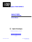
This manual contains information required to test, troubleshoot, and repair
the Agilent E1445A C-Size VXI Arbitrary Function Generator (AFG). See
the Agilent E1445A User’s Manual for additional information. Figure 1-1
shows the Agilent E1445A. This chapter includes the following sections:
•
•
•
•
•
•
Introduction
Safety Considerations
Inspection/Shipping
Environment
AFG Description
Recommended Test Equipment
Figure 1-1. E1445A Arbitrary Function Generator
Agilent E1445A Service Manual
General Information 9
Safety
Considerations
This product is a Safety Class I instrument that is provided with a protective
earth terminal when installed in the mainframe. The mainframe, AFG, and
all related documentation should be reviewed for familiarization with safety
markings and instructions before operation or service.
Refer to the WARNINGS page (page 4) in this manual for a summary of
safety information. Safety information for preventive maintenance, testing,
and service follows and is also found throughout this manual.
Warnings and
Cautions
WARNING
This section contains WARNINGS which must be followed for your
protection and CAUTIONS which must be followed to avoid damage to the
equipment when performing instrument maintenance or repair.
SERVICE-TRAINED PERSONNEL ONLY. The information in this
manual is for service-trained personnel who are familiar with
electronic circuitry and are aware of the hazards involved. To
avoid personal injury or damage to the instrument, do not
perform procedures in this manual or do any servicing unless
you are qualified to do so.
CHECK MAINFRAME POWER SETTINGS. Before applying
power, verify that the mainframe setting matches the line
voltage and that the correct fuse is installed. An uninterruptible
safety earth ground must be provided from the main power
source to the supplied power cord set.
GROUNDING REQUIREMENTS. Interruption of the protective
(grounding) conductor (inside or outside the mainframe) or
disconnecting the protective earth terminal will cause a
potential shock hazard that could result in personal injury.
(Grounding one conductor of a two-conductor outlet is not
sufficient protection.)
IMPAIRED PROTECTION. Whenever it is likely that instrument
protection has been impaired, the mainframe must be made
inoperative and be secured against any unintended operation.
REMOVE POWER IF POSSIBLE. Some procedures in this
manual may be performed with power supplied to the
mainframe while protective covers are removed. Energy
available at many points may, if contacted, result in personal
injury. (If maintenance can be performed without power applied,
the power should be removed.)
10 General Information
Agilent E1445A Service Manual
WARNING
USING AUTOTRANSFORMERS. If the mainframe is to be
energized via an autotransformer (for voltage reduction) make
sure the common terminal is connected to neutral (that is, the
grounded side of the main’s supply).
CAPACITOR VOLTAGES. Capacitors inside the mainframe may
remain charged even when the mainframe has been
disconnected from its source of supply.
USE PROPER FUSES. For continued protection against fire
hazard, replace the line fuses only with fuses of the same
current rating and type (such as normal blow, time delay, etc.).
Do not use repaired fuses or short-circuited fuseholders.
CAUTION
Static electricity is a major cause of component failure. To prevent
damage to the electrical components in the AFG, observe anti-static
techniques whenever working on the AFG.
Agilent E1445A Service Manual
General Information 11
Inspection/
Shipping
This section describes initial (incoming) inspection and shipping guidelines
for the AFG.
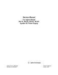
Initial
Inspection
WARNING
Use the steps in Figure 1-2 as guidelines to perform initial inspection of
the AFG.
To avoid possible hazardous electrical shock, do not perform
electrical tests if there are signs of shipping damage to the
shipping container or to the instrument.
Figure 1-2. Initial (Incoming) Inspection Guidelines
12 General Information
Agilent E1445A Service Manual
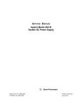
Shipping
Guidelines
Follow the steps in Figure 1-3 to return the AFG to an Agilent Technologies
Sales and Support Office or Service Center.
1. Prepare the module
• Remove user wiring from terminal block
• Attach tag to module that identifies:
• Owner
• Model Number/Serial Number
• Service Required
• Place tagged device in approved anti-static bag
2. Package the module
• Place packaged module in shipping carton*
• Place 75 to 100 mm (3 to 4 inches) of
shock-absorbing material around the module
• Seal the shipping container securely
• Mark the shipping container FRAGILE
3. Ship the module to Agilent Technologies
• Place address label on shipping carton
• Send carton to Agilent Technologies
* We recommend that you use the same shipping materials as those used in factory packaging (available from
Agilent Technologies). For other (commercially-available) shipping materials, use a double-wall carton with
minimum 2.4 MPa (350 psi) test.
Figure 1-3. Packaging/Shipping Guidelines
Agilent E1445A Service Manual
General Information 13
Environment
Environment
The recommended operating environment for the Agilent E1445A
AFG is:
Temperature
Humidity
Operating
0oC to +55oC
<65% relative (0oC to +40oC)
Storage and
Shipment
-40oC to +75oC
<65% relative (0oC to +40oC)
AFG
Description
The Agilent E1445A Arbitrary Function Generator is a VXIbus C-size,
message-based instrument. The AFG can operate in a C-size VXIbus
mainframe using an Agilent E1405/E1406 Command Module and Standard
Commands for Programmable Instruments (SCPI).
The AFG has 13 bits of resolution (including sign). It uses a sequencer
architecture, with 256K points of Segment storage and 32K points of
Sequence storage. The AFG has two internal timebases, 40 MHz and
(approximately) 42.9 MHz.
AFG
Specifications
AFG
Options
AFG
Serial Numbers
AFG specifications are listed in Appendix A of the Agilent E1445A User’s
Manual. These specifications are the performance standards or limits
against which the instrument may be tested.
Arbitrary Waveform Generation Software for HP 9000 Series 300
computers can be ordered as Option 005.
Figure 1-4 shows Agilent Technologies’ serial number structure. AFG’s
covered by this manual are identified by a serial number prefix listed on the
title page.
Agilent
Figure 1-4. Agilent Serial Numbers
14 General Information
Agilent E1445A Service Manual
Recommended
Test Equipment
Table 1-1 lists the test equipment recommended for testing, adjusting, and
servicing the AFG. Essential requirements for each piece of test equipment
are described in the Requirements column.
Table 1-1. Recommended Test Equipment
Instrument
Requirements
Recommended
Model
Use*
Controller, GP-IB
GP-IB compatibility as defined by IEEE
Standard 488-1988 and the identical
ANSI Standard MC1.1: SH1, AH1, T2,
TE0, L2, LE0, SR0, RL0, PP0, DC0,
DT0, and C1, 2, 3, 4, 5.
HP 9000 Series 300
or
IBM Compatible PC
with HP BASIC
F,O,P,
A,T
Mainframe
Compatible with AFG
Agilent E1401B/T or
E1421B
F,O,P,
A,T
Command Module
10 MHz Clk Out
TTL compatible Trig Out
Agilent E1405B or
Agilent E1406A
F,O,P,
A,T
Digital Multimeter
DCV, ACV, 4-wire ohms w/offset comp
Agilent 3458A
O,P,A
Power Meter
Frequency Range: 400 kHz - 10.8 MHz
Agilent 8902A
O,P,A
Power Sensor
Frequency Range: 400 kHz - 10.8 MHz
Agilent 11722A
O,P,A
Counter
Frequency Range: 100 Hz - 45 MHz
Agilent 5334A/B
O,P
Spectrum Analyzer
Frequency Range: 100 kHz - 150 MHz
Agilent 8566B
O,P,A
Oscilloscope
General Purpose
Bandwidth: 20 MHz
Agilent 54111D
F
50 Ω feed-thru
termination
50 ±0.10 Ω
Agilent 11048C
O,P,A
* F = Functional Verification, O = Operation Verification Tests, P = Performance Verification
Tests, A = Adjustments, T = Troubleshooting
Agilent E1445A Service Manual
General Information 15
16 General Information
Agilent E1445A Service Manual
Chapter 2
Verification Tests
Introduction
The three levels of test procedures described in this chapter are used to
verify that the Agilent E1445A:
• is fully functional (Functional Verification)
• meets selected testable specifications (Operation Verification)
• meets all testable specifications (Performance Verification)
WARNING
Do not perform any of the following verification tests unless
you are a qualified, service-trained technician and have read the
WARNINGS and CAUTIONS in Chapter 1.
Test Conditions/
Procedures
See Table 1-1 for test equipment requirements. You should complete the
Performance Verification tests at least once a year. For heavy use or severe
operating environments, perform the tests more often.
Before performing these tests, allow the AFG to warm up for at least one hour.
The temperature should be within ±5oC of Tcal (the temperature of the most
recent calibration), and between 18oC and 28oC.
The verification tests assume that the person performing the tests
understands how to operate the mainframe, the AFG, and specified test
equipment. The test procedures do not specify equipment settings for test
equipment, except in general terms. It is assumed that a qualified,
service-trained technician will select and connect the cables, adapters, and
probes required for the test.
Performance
Test Record
The results of each Performance Verification test may be recorded in Table
2-11, Agilent E1445A Performance Test Record. This form can be copied.
Verification Test
Examples
Each verification test procedure includes an example program that performs
the test. All example programs assume the following configuration:
• Controller is an HP 9000 Series 200/300 computer
• Programming language is HP BASIC
• AFG address is 70910
Agilent E1445A Service Manual
Verification Tests 17
Command Coupling
Many of the AFG SCPI commands are value-coupled. In order to prevent
"Settings Conflict" errors, coupled commands must be sent contiguously by
placing them in the same program line, or by suppressing the end-of-line
terminator. (For more information on command coupling and syntax, see
Chapter 1 of the Agilent E1445A User’s Manual). In HP BASIC, the
end-of-line terminator can be suppressed by linking the commands with a
semi-colon (;) and a colon (:), as illustrated below:
ROSC:SOUR INT1;
:TRIG:SOUR INT1
In the Example programs, these commands would appear as follows:
OUTPUT 70910;"ROSC:SOUR:INT1;";
OUTPUT 70910;":TRIG:SOUR:INT1"
Functional
Verification
The purpose of these tests is to verify that the AFG is functioning properly
and that all front panel inputs and outputs are working. No attempt is made
to verify that the AFG is meeting specifications. Functional Verification for
the AFG includes the following tests:
•
•
•
•
•
NOTE
Self-Test
Ref In/Marker Out Test
Start Arm In Test
Gate In Test
Output Relay Test
For a quick functional check of the AFG, perform only the Self-Test.
An example program that performs all of the Functional Verification tests is
included at the end of this section. An Agilent E1405/E1406 Command
Module is required for this program.
NOTE
18 Verification Tests
Some of the tests use the "TRIG OUT" port of the Command Module. This
port uses negative logic, i.e., the high voltage is a logical 0 and the low
voltage is a logical 1.
Agilent E1445A Service Manual
Functional Verification: Self-Test
Description
The AFG self-test performs the following internal checks:
•
•
•
•
•
•
•
•
•
•
•
•
•
internal interrupt lines
waveform select RAM
segment sequence RAM
waveform segment RAM
DDS/NCO operation
sine wave generation
arbitrary waveform generation
marker generation
waveform cycle and arm counters
sweep timer
frequency-shift keying
stop trigger
DC analog parameters (amplitude, offset, attenuators, filters,
calibration DACs)
Test Procedure
1. Remove any connections to the AFG front panel.
2. Reset the AFG:
*RST;*CLS
Reset AFG and clear
status registers
3. Execute the AFG self-test:
*TST?
Self-test command
4. Read the result. A "0" indicates that the test passed. A "1" indicates a
failure. Read the error queue using the SYST:ERR? command until
the error message is "No error".
Agilent E1445A Service Manual
Verification Tests 19
Functional Verification: Ref In/Marker Out Test
Description
The purpose of this test is to check the Ref/Sample In and Marker Out ports.
An external reference is connected to the Ref/Sample In port and sent to the
Marker Out port.
Test Procedure
1. Reset the AFG:
*RST;*CLS
Reset AFG and clear
status registers
2. Set up equipment as shown in Figure 2-1:
Figure 2-1. Ref/Sample In Test Setup
3. Set up the AFG to output the external reference to the "Marker Out"
port:
ROSC:SOUR EXT
MARK:FEED "ROSC"
INIT:IMM
External ref oscillator
Marker source is ROSC
Initiate
4. Verify that the scope shows a 10 MHz squarewave.
20 Verification Tests
Agilent E1445A Service Manual
Functional Verification: Start Arm In Test
Description
The purpose of this test is to check the Start Arm In port. The "TRIG OUT"
port of the Command Module is used to send a Start Arm signal to the AFG.
Test Procedure
1. Reset the AFG:
*RST;*CLS
Reset AFG and clear
status registers
2. Set up equipment as shown in Figure 2-2:
Figure 2-2. Start Arm In Test Setup
3. Send the following commands to the Command Module to output 0 V
to the "Trig Out" port:
*RST
OUTP:EXT:STAT ON
OUTP:EXT:SOUR INT
OUTP:EXT:LEV 1
Agilent E1445A Service Manual
Verification Tests 21
Functional Verification: Start Arm In Test (cont’d)
Test Procedure
(cont’d)
4. Set up the AFG to output a 1 MHz sinewave, with an external Start
Arm source:
FREQ 1E6;
:VOLT 4VPP
ARM:LAY2:SOUR EXT
INIT:IMM
Set freq to 1 MHz
Set AFG amplitude
External Start Arm
source
Initiate
5. Verify that no signal appears on the scope. Send the following
command to the Command Module to provide a Start Arm signal to
the AFG:
OUTP:EXT:LEV 0
6. Verify that a 1 MHz sinewave appears on the scope.
22 Verification Tests
Agilent E1445A Service Manual
Functional Verification: Gate In Test
Description
The purpose of this test is to check the gating function. The "TRIG OUT"
port of the Command Module is used to gate the output.
Test Procedure
1. Reset the AFG:
*RST;*CLS
Reset AFG and clear
status registers
2. Set up the equipment as shown in Figure 2-3.
Figure 2-3. Gate In Test Setup
3. Send the following commands to the Command Module to enable the
"Trig Out" port:
*RST
OUTP:EXT:STAT ON
OUTP:EXT:SOUR INT
Agilent E1445A Service Manual
Verification Tests 23
Functional Verification: Gate In Test (cont’d)
Test Procedure
(cont’d)
4. Set up the AFG to output a 1 MHz sinewave with an external gate
source:
TRIG:GATE:SOUR EXT;
:TRIG:GATE:STAT ON;
:FREQ 1E6;
:VOLT 4VPP
INIT:IMM
External gate source
Enable gate
Set freq to 1 MHz
Set AFG amplitude
Initiate
5. Send the following command to the Command Module to set the
level at the "Trig Out" port to 5 V. Verify that the scope shows a 1
MHz sinewave.
OUTP:EXT:LEV 0
6. Send the following command to the Command Module to set the
level at the "Trig Out" port to 0 V. Verify that the scope shows a DC
signal.
OUTP:EXT:LEV 1
24 Verification Tests
Agilent E1445A Service Manual
Functional Verification: Output Relay Test
Description
The purpose of this test is to check the output relay.
Test Procedure
1. Reset the AFG:
*RST;*CLS
Reset AFG and clear
status registers
2. Set up equipment as shown in Figure 2-4:
Figure 2-4. Output Relay Test Setup
3. Set up the AFG to output a 1 MHz sinewave:
FREQ 1E6;
:VOLT 4VPP
INIT:IMM
Set freq to 1 MHz
Set AFG amplitude
Initiate
4. Verify that a 1 MHz sinewave appears on the scope.
5. Disable the Output relay:
OUTP OFF
6. Verify that no signal appears on the scope.
Agilent E1445A Service Manual
Verification Tests 25
Functional Verification
Example Program
This program performs the Functional Verification Tests for the AFG. An Agilent E1405/E1406 Command
Module is required for this test.
10! RE-STORE "FUNC_TEST"
20 COM @Afg,@Cmd_mod,INTEGER Done
30 !
40 !---------- Set up I/O paths ---------50 ASSIGN @Afg TO 70910
60 ASSIGN @Cmd_mod TO 70900
70 !
80 !---------- Initialize AFG & Command Module ---------90 Reset_afg
100 !
110 !Set up Command Module ’TRIG OUT’ port
120 OUTPUT @Cmd_mod;"*RST"
130 OUTPUT @Cmd_mod;"OUTP:EXT:STAT ON"
140 OUTPUT @Cmd_mod;"OUTP:EXT:SOUR INT"
150 !
160 !---------- Perform tests ---------170 CLEAR SCREEN
180 PRINT "Agilent E1445A FUNCTIONAL VERIFICATION TESTS"
190 PRINT
200 !
210 !Oscilloscope settings
220 PRINT "Set scope to: 2 V/div, .02 usec/div"
230 PRINT
240 Wait_for_cont
250 !
260 CALL Self_test
!Self-Test
270 CALL Ref_in
!Ref In/Marker Out Test
280 !
290 !Oscilloscope settings
300 CLEAR SCREEN
310 PRINT "Set scope to: 2 V/div, .2 usec/div"
320 PRINT
330 Wait_for_cont
340 !
350 CALL Start_arm
!Start Arm In Test
360 CALL Gate_in
!Gate In Test
370 CALL Output_relay
!Output Relay Test
380 !
390 Quit: !
400 Reset_afg
410 CLEAR SCREEN
420 DISP "Functional Tests completed."
430 END
(Continued on next page)
26 Verification Tests
Agilent E1445A Service Manual
Functional Verification
Example Program (cont’d)
450
460
470
480
490
500
510
520
530
540
550
560
570
580
590
600
610
620
630
640
650
660
670
680
690
700
710
720
730
740
750
760
770
780
790
800
810
820
830
840
850
860
870
880
!---------- Subprograms ---------SUB Reset_afg
COM @Afg,@Cmd_mod,INTEGER Done
OUTPUT @Afg;"*RST;*CLS"
!Reset AFG and clear Status register
WAIT 1
SUBEND
!
SUB Self_test
COM @Afg,@Cmd_mod,INTEGER Done
DIM Message$[255]
!
Reset_afg
!
CLEAR SCREEN
PRINT "SELF-TEST"
PRINT
!
!Test connections
PRINT "Remove any connections from the E1445A front panel."
PRINT "Press ’Continue’ to initiate Self-Test."
PRINT
Wait_for_cont
!
!Perform test
OUTPUT @Afg;"*TST?"
!Self-test command
ENTER @Afg;Result
!Get result
!
IF Result=0 THEN
PRINT "Self-test passed."
ELSE
PRINT "Self-test failed."
PRINT "The following error(s) occurred:"
REPEAT
OUTPUT @Afg;"SYST:ERR?"
!Check for errors
ENTER @Afg;Message$
PRINT " "&Message$
UNTIL POS(Message$,"No error")
END IF
Wait_for_cont
SUBEND
!
SUB Ref_in
COM @Afg,@Cmd_mod,INTEGER Done
!
(Continued on next page)
Agilent E1445A Service Manual
Verification Tests 27
Functional Verification
Example Program (cont’d)
890
900
910
920
930
940
950
960
970
980
990
1000
1010
1020
1030
1040
1050
1060
1070
1080
1090
1100
1110
1120
1130
1140
1150
1160
1170
1180
1190
1200
1210
1220
1230
1240
1250
1260
1270
1280
1290
1300
1310
1320
1330
Reset_afg
!
CLEAR SCREEN
PRINT "REF IN/MARKER OUT TEST"
PRINT
!
!Test connections
PRINT "Connect Scope to ’Marker Out’ on the E1445A."
PRINT "Connect Command Module ’Clk Out’ to ’Ref/Sample In’ on the E1445A."
PRINT
Wait_for_cont
!
!Perform test
OUTPUT @Afg;"ROSC:SOUR EXT"
!External ref osc source
OUTPUT @Afg;"MARK:FEED ""ROSC"""
!Marker source is ’ROSC’
OUTPUT @Afg;"INIT:IMM"
!Initiate
!
PRINT "Verify that the scope shows a 10 MHz squarewave."
Wait_for_cont
SUBEND
!
SUB Start_arm
COM @Afg,@Cmd_mod,INTEGER Done
!
Reset_afg
!
CLEAR SCREEN
PRINT "START ARM TEST"
PRINT
!
!Test connections
PRINT "Connect Scope to the E1445A Output."
PRINT "Connect Command Module ’Trig Out’ to ’Start Arm In’ on the E1445A."
PRINT
Wait_for_cont
!
!Set Command Module’s ’TRIG OUT’ to 0V (E1405 uses neg logic)
OUTPUT @Cmd_mod;"OUTP:EXT:LEV 1"
!
!Perform test
OUTPUT @Afg;"FREQ 1E6;";
!Set freq to 1 MHz
OUTPUT @Afg;":VOLT 4VPP"
!Set amplitude
OUTPUT @Afg;"ARM:LAY2:SOUR EXT"
!Start Arm source is EXT
OUTPUT @Afg;"INIT:IMM"
!Initiate
!
(Continued on next page)
28 Verification Tests
Agilent E1445A Service Manual
Functional Verification
Example Program (cont’d)
1340 PRINT "Verify that no signal appears on the scope."
1350 PRINT "Press ’Continue’ to send a START ARM."
1360 PRINT
1370 Wait_for_cont
1380 !
1390 !Set ’TRIG OUT’ to 5V
1400 OUTPUT @Cmd_mod;"OUTP:EXT:LEV 0"
1410 !
1420 PRINT "Verify that the scope shows a 1 MHz sinewave."
1430 Wait_for_cont
1440 SUBEND
1450 !
1460 SUB Gate_in
1470 COM @Afg,@Cmd_mod,INTEGER Done
1480 !
1490 Reset_afg
1500 !
1510 CLEAR SCREEN
1520 PRINT "GATE IN TEST"
1530 PRINT
1540 !
1550 !Test connections
1560 PRINT "Connect Scope to the E1445A Output."
1570 PRINT "Connect Command Module ’Trig Out’ to ’Stop Trig/FSK/Gate In’ on the E1445A."
1580 PRINT
1590 Wait_for_cont
1600 !
1610 !Perform test
1620 OUTPUT @Afg;"TRIG:GATE:SOUR EXT;";
!Gate source is EXT
1630 OUTPUT @Afg;":TRIG:GATE:STAT ON;";
!Enable gate
1640 OUTPUT @Afg;":FREQ 1E6;";
!Set freq to 1 MHz
1650 OUTPUT @Afg;":VOLT 4VPP"
!Set amplitude
1660 OUTPUT @Afg;"INIT:IMM"
!Initiate
1670 !
1680 PRINT "Verify that the signal displayed on the scope toggles between"
1690 PRINT "a 1 MHz sinewave and a DC signal at 1 second intervals."
1700 !
1710 ON KBD ALL CALL Key_press
1720 DISP "Press any key to continue"
1730 !
1740 Done=0
1750 !Send pulses to ’TRIG OUT’ BNC until a key is pressed
(Continued on next page)
Agilent E1445A Service Manual
Verification Tests 29
Functional Verification
Example Program (cont’d)
1760
1770
1780
1790
1800
1810
1820
1830
1840
1850
1860
1870
1880
1890
1900
1910
1920
1930
1940
1950
1960
1970
1980
1990
2000
2010
2020
2030
2040
2050
2060
2070
2080
2090
2100
2110
2120
2130
REPEAT
OUTPUT @Cmd_mod;"OUTP:EXT:LEV 1"
WAIT 1
OUTPUT @Cmd_mod;"OUTP:EXT:LEV 0"
WAIT 1
UNTIL Done
OFF KBD
SUBEND
!
SUB Output_relay
COM @Afg,@Cmd_mod,INTEGER Done
!
Reset_afg
!
CLEAR SCREEN
PRINT "OUTPUT RELAY TEST"
PRINT
!
!Test connections
PRINT "Connect Scope to the E1445A Output."
PRINT
Wait_for_cont
!
!Perform test
OUTPUT @Afg;"FREQ 1E6;";
!Set freq to 1 MHz
OUTPUT @Afg;":VOLT 4VPP"
!Set amplitude
OUTPUT @Afg;"INIT:IMM"
!Initiate
!
PRINT "Verify that the scope shows a 1 MHz sinewave."
PRINT "Press ’Continue’ to disable the E1445A output."
PRINT
Wait_for_cont
!
OUTPUT @Afg;"OUTP OFF"
!Open Output relay
PRINT "Verify that no signal appears on the scope."
Wait_for_cont
SUBEND
!
(Continued on next page)
30 Verification Tests
Agilent E1445A Service Manual
Functional Verification
Example Program (cont’d)
2140
2150
2160
2170
2180
2190
2200
2210
2220
2230
2240
SUB Key_press
COM @Afg,@Cmd_mod,INTEGER Done
Done=1
DISP
SUBEND
!
SUB Wait_for_cont
DISP "Press ’Continue’ when ready"
PAUSE
DISP
SUBEND
Agilent E1445A Service Manual
Verification Tests 31
Operation
Verification
Operation Verification is a subset of the Performance Verification tests that
follow. For the AFG, Operation Verification consists of the following tests:
• DC Accuracy
• AC Accuracy
• Total Harmonic Distortion
Performance
Verification
The procedures in this section are used to test the AFG’s electrical
performance using the specifications in Appendix A of the Agilent E1445A
User’s Manual as the performance standards. These tests are suitable for
incoming inspection, troubleshooting, and preventive maintenance. The
results of the Performance Verification tests should be recorded in the
Performance Test Record (Table 2-11).
Performance Verification includes the following tests:
32 Verification Tests
Test #
Test Name
2-1
2-2
2-3
2-4
2-5
2-6
2-7
2-8
2-9
2-10
DC Zeros
DC Accuracy
DC Offset
AC Accuracy
AC Flatness - 250 kHz filter
AC Flatness - 10 MHz filter
Frequency Accuracy
Duty Cycle
Total Harmonic Distortion
Spurious/Non-harmonic Distortion
Agilent E1445A Service Manual
Test 2-1: DC Zeros
Description
The purpose of this test is to verify that the AFG meets its specifications for
DCV accuracy for an output of zero volts. An arbitrary waveform
consisting of zeros is used. The amplitude is varied in order to test each
attenuator.
Equipment Setup
• Connect equipment as shown in Figure 2-5
• Set DMM to: DCV, 100 mV range
Figure 2-5. Equipment Setup for Test 2-1 thru Test 2-4
Test Procedure
1. Reset the AFG:
*RST;*CLS
Reset AFG and clear
status registers
2. Delete all sequences and segments from memory:
LIST:SSEQ:DEL:ALL
LIST:SEGM:DEL:ALL
Agilent E1445A Service Manual
Delete all sequences
Delete all segments
Verification Tests 33
Test 2-1: DC Zeros (cont’d)
Test Procedure
(cont’d)
3. Create a user-defined waveform made up of zeros:
LIST:SEGM:SEL ZEROS
LIST:SEGM:DEF 8
LIST:SEGM:VOLT 0,0,0,0,0,0,0,0
Select segment name
# of segment points
Segment list
LIST:SSEQ:SEL DC_ZEROS
LIST:SSEQ:DEF 1
LIST:SSEQ:SEQ ZEROS
Select sequence name
# of segments
Sequence list
4. Set up the AFG to output the waveform defined above:
ROSC:SOUR CLK10;
:VOLT MAX;
:OUTP:LOAD INF;
:FUNC USER
FUNC:USER DC_ZEROS
INIT:IMM
Select 10 MHz clock
Set amplitude
Infinite load
Select user waveform
Select sequence
Initiate waveform
Perform steps 5 - 7 for each amplitude listed in Table 2-1:
5. Set the AFG output filter as specified in Table 2-1. Use the
appropriate command(s) below:
OUTP:FILT OFF
or
OUTP:FILT:FREQ 250KHZ
OUTP:FILT ON
or
OUTP:FILT:FREQ 10MHZ
OUTP:FILT ON
Disable filter
Select 250 kHz filter
Enable filter
Select 10 MHz filter
Enable filter
6. Set the AFG output amplitude:
VOLT <amplitude>
Set amplitude
where <amplitude> is the value specified in Table 2-1.
7. Trigger the DMM and record the reading in Table 2-11.
34 Verification Tests
Agilent E1445A Service Manual
Test 2-1: DC Zeros (cont’d)
Test Procedure
(cont’d)
Table 2-1. DC Zeros Test Points
Attenuation
(dB)
Amplitude
(volts)
Filter
Test Limits
(volts)
0
.99
1
2
4
8
13
14
30
10.23750
9.13469
9.12416
8.13192
6.45941
4.07560
2.29187
2.04263
0.32372
None
None
None
None
None
None
None
None
None
0 ± 0.0220
0 ± 0.0220
0 ± 0.0220
0 ± 0.0220
0 ± 0.0220
0 ± 0.0220
0 ± 0.0220
0 ± 0.0044
0 ± 0.0044
0
.99
1
2
4
8
13
14
30
10.23750
9.13469
9.12416
8.13192
6.45941
4.07560
2.29187
2.04263
0.32372
250 kHz
250 kHz
250 kHz
250 kHz
250 kHz
250 kHz
250 kHz
250 kHz
250 kHz
0 ± 0.0220
0 ± 0.0220
0 ± 0.0220
0 ± 0.0220
0 ± 0.0220
0 ± 0.0220
0 ± 0.0220
0 ± 0.0044
0 ± 0.0044
0
.99
1
2
4
8
13
14
30
10.23750
9.13469
9.12416
8.13192
6.45941
4.07560
2.29187
2.04263
0.32372
10 MHz
10 MHz
10 MHz
10 MHz
10 MHz
10 MHz
10 MHz
10 MHz
10 MHz
0 ± 0.0220
0 ± 0.0220
0 ± 0.0220
0 ± 0.0220
0 ± 0.0220
0 ± 0.0220
0 ± 0.0220
0 ± 0.0044
0 ± 0.0044
Agilent E1445A Service Manual
Verification Tests 35
Test 2-1: DC Zeros (cont’d)
Example Program
This program performs the DC Zeros test. An arbitrary waveform, consisting of zeros, is used with various
amplitudes to test a variety of attenuator and filter combinations.
10!
20
30
40
50
60
70
80
90
100
110
120
130
140
150
160
170
180
190
200
210
220
230
240
250
260
270
280
290
300
310
320
330
340
350
360
370
380
390
400
410
420
430
RE-STORE "DC_ZEROS"
COM @Afg
DIM Attn(1:9),Vout(1:9)
!
!---------- Set up I/O path and reset AFG ---------ASSIGN @Afg TO 70910
OUTPUT @Afg;"*RST;*CLS"
!Reset AFG
!
!---------- Initialize variables ---------DATA 0,.99,1,2,4,8,13,14,30
READ Attn(*)
!Read in attenuations
!
DATA 10.2375,9.13469,9.12416,8.13192,6.45941,4.0756
DATA 2.29187,2.04263,0.32372
READ Vout(*)
!
!---------- Set up DMM ---------PRINT "Set up DMM:"
PRINT
PRINT " Function -- DCV"
PRINT " Range -- 100 mV"
PRINT
PRINT "Connect DMM HI and LO to AFG Output."
DISP "Press ’Continue’ when ready"
PAUSE
CLEAR SCREEN
!
!---------- Set up AFG ---------OUTPUT @Afg;"*RST"
!Reset AFG
OUTPUT @Afg;"LIST:SSEQ:DEL:ALL"
!Delete all sequences
OUTPUT @Afg;"LIST:SEGM:DEL:ALL"
!Delete all segments
WAIT .5
OUTPUT @Afg;"ROSC:SOUR CLK10;";
!10MHZ clock
OUTPUT @Afg;":VOLT MAX;";
!MAX output
OUTPUT @Afg;":OUTP:LOAD INF;";
!Infinite load
OUTPUT @Afg;":FUNC USER"
!User waveform
!
CALL Def_seq_zeros
!Define waveform
OUTPUT @Afg;"FUNC:USER DC_ZEROS"
!Select sequence
OUTPUT @Afg;"INIT:IMM"
!
!---------- Perform test ---------PRINT "ATTEN","FILTER","AMPLITUDE"
(Continued on next page)
36 Verification Tests
Agilent E1445A Service Manual
Test 2-1: DC Zeros (cont’d)
Example Program (cont’d)
440
460
470
480
490
500
510
520
530
540
550
560
570
580
590
600
610
620
630
640
650
660
670
680
690
700
710
720
730
740
750
760
770
780
790
800
810
820
830
840
PRINT
FOR Filter=0 TO 2
SELECT Filter
CASE 0
OUTPUT @Afg;"OUTP:FILT OFF"
Filter$="NONE"
CASE 1
OUTPUT @Afg;"OUTP:FILT:FREQ 250KHZ"
OUTPUT @Afg;"OUTP:FILT ON"
Filter$="250 kHz"
CASE 2
OUTPUT @Afg;"OUTP:FILT:FREQ 10MHZ"
OUTPUT @Afg;"OUTP:FILT ON"
Filter$="10 MHz"
END SELECT
!
FOR I=1 TO 9
OUTPUT @Afg;":VOLT "&VAL$(Vout(I))
PRINT Attn(I),Filter$,Vout(I)
!
DISP "Record DMM reading, then press ’Continue’"
PAUSE
DISP
NEXT I
PRINT
NEXT Filter
!
OUTPUT @Afg;"*RST;*CLS"
END
!
SUB Def_seq_zeros
COM @Afg
OUTPUT @Afg;"LIST:SEGM:SEL ZEROS"
OUTPUT @Afg;"LIST:SEGM:DEF 8"
OUTPUT @Afg;"LIST:SEGM:VOLT 0,0,0,0,0,0,0,0"
!
OUTPUT @Afg;"LIST:SSEQ:SEL DC_ZEROS"
OUTPUT @Afg;"LIST:SSEQ:DEF 1"
OUTPUT @Afg;"LIST:SSEQ:SEQ ZEROS"
SUBEND
Agilent E1445A Service Manual
!No filter
!250KHZ filter
!10MHZ filter
!Loop through atten’s
!Set AFG amplitude
!Next attenuation
!Next filter
!Reset AFG
!Segment name
!Segment length
!Voltage points
!Sequence name
!# of segments
!Segment list
Verification Tests 37
Test 2-2: DC Accuracy
Description
The purpose of this test is to verify that the AFG meets its specifications for
DC accuracy.
Equipment Setup
• Connect equipment as shown in Figure 2-5
• Set DMM to DCV, autorange
Test Procedure
1. Reset the AFG:
*RST;*CLS
Reset AFG and clear
status registers
2. Set up the AFG to output a DC signal:
FUNC DC;
:OUTP:LOAD INF;
:VOLT MAX
Select DC waveform
Infinite load
Set amplitude
Perform steps 3 - 5 for each amplitude listed in Table 2-2:
3. Set up the AFG output filter as specified in Table 2-2. Use the
appropriate command(s) below:
OUTP:FILT OFF
or
OUTP:FILT:FREQ 250KHZ
OUTP:FILT ON
or
OUTP:FILT:FREQ 10MHZ
OUTP:FILT ON
Disable filter
Select 250 kHz filter
Enable filter
Select 10 MHz filter
Enable filter
4. Set the AFG output amplitude:
VOLT <amplitude>
Set amplitude
where <amplitude> is the value specified in Table 2-2.
5. Trigger the DMM and record the reading.
38 Verification Tests
Agilent E1445A Service Manual
Test 2-2: DC Accuracy (cont’d)
Test Procedure
(cont’d)
Table 2-2. DC Accuracy Test Points
Amplitude
(volts)
Filter
Test Limits
(volts)
10.2375
5.0
0.0
-5.0
-10.24
10.2375
-10.24
10.2375
-10.24
None
None
None
None
None
250 kHz
250 kHz
10 MHz
10 MHz
10.2375 ± 0.0512
5.0 ± 0.0355
0.0 ± 0.0205
-5.0 ± 0.0355
-10.24 ± 0.0512
10.2375 ± 0.0512
-10.24 ± 0.0512
10.2375 ± 0.0512
10.24 ± 0.0512
Example Program
This program performs the DC Accuracy test.
10! RE-STORE "DC_LEVELS"
20
DIM Vout(1:9),Filter(1:9)
30
!
40
!---------- Set up I/O path and reset AFG ----------50
ASSIGN @Afg TO 70910
60
OUTPUT @Afg;"*RST;*CLS"
!Reset AFG
70
!
80
!---------- Initialize variables ---------90
DATA 10.2375,5.0,0,-5.0,-10.24,10.2375,-10.24,10.2375,-10.24
100 READ Vout(*)
110 !
120 DATA 0,0,0,0,0,1,1,2,2
130 READ Filter(*)
140 !
150 !---------- Set up DMM ---------160 CLEAR SCREEN
170 PRINT "Set up DMM:"
180 PRINT
190 PRINT " Function -- DCV"
200 PRINT " Range -- AUTO"
210 PRINT
220 PRINT "Connect DMM HI and LO to AFG Output."
230 DISP "Press ’Continue’ when ready"
240 PAUSE
250 CLEAR SCREEN
Agilent E1445A Service Manual
Verification Tests 39
Test 2-2: DC Accuracy (cont’d)
Example Program (cont’d)
270
280
290
300
310
320
330
340
350
360
370
380
390
400
410
420
430
440
450
460
470
480
490
500
510
520
530
540
550
560
570
580
590
600
610
620
!---------- Set up AFG ---------OUTPUT @Afg;"*RST"
WAIT .5
OUTPUT @Afg;"FUNC DC;";
OUTPUT @Afg;":OUTP:LOAD INF;";
OUTPUT @Afg;":VOLT MAX"
!
!---------- Perform test ---------PRINT "FILTER","AMPLITUDE"
PRINT
!
FOR I=1 TO 9
SELECT Filter(I)
CASE 0
OUTPUT @Afg;"OUTP:FILT OFF"
Filter$="NONE"
CASE 1
OUTPUT @Afg;"OUTP:FILT:FREQ 250KHZ"
OUTPUT @Afg;"OUTP:FILT ON"
Filter$="250 kHz"
CASE 2
OUTPUT @Afg;"OUTP:FILT:FREQ 10MHZ"
OUTPUT @Afg;"OUTP:FILT ON"
Filter$="10 MHz"
END SELECT
!
OUTPUT @Afg;"VOLT "&VAL$(Vout(I))
PRINT Filter$,Vout(I)
!
DISP "Record DMM reading, then press ’Continue’"
PAUSE
DISP
NEXT I
!
OUTPUT @Afg;"*RST;*CLS"
END
40 Verification Tests
!Reset AFG
!DC function
!Infinite load
!MAX output
!No filter
!250kHz filter
!10MHz filter
!Set amplitude
!Reset AFG
Agilent E1445A Service Manual
Test 2-3: DC Offset
Description
The purpose of this test is to verify that the AFG meets its specifications for
DC offset accuracy.
Equipment Setup
• Connect equipment as shown in Figure 2-5
• Set DMM to DCV, autorange
Test Procedure
1. Reset the AFG:
*RST;*CLS
Reset AFG and clear
status registers
2. Delete all sequences and segments from memory:
LIST:SSEQ:DEL:ALL
LIST:SEGM:DEL:ALL
Delete all sequences
Delete all segments
3. Create a user-defined waveform made up of zeros:
LIST:SEGM:SEL ZEROS
LIST:SEGM:DEF 8
LIST:SEGM:VOLT 0,0,0,0,0,0,0,0
Select segment name
# of segment points
Segment list
LIST:SSEQ:SEL DC_ZEROS
LIST:SSEQ:DEF 1
LIST:SSEQ:SEQ ZEROS
Select sequence name
# of segments
Sequence list
4. Set up the AFG to output the waveform defined above:
ROSC:SOUR CLK10;
:OUTP:LOAD INF;
:VOLT MAX;
:FUNC USER
FUNC:USER DC_ZEROS
INIT:IMM
Agilent E1445A Service Manual
Select 10 MHz clock
Infinite load
Set amplitude
Select user waveform
Select sequence
Initiate waveform
Verification Tests 41
Test 2-3: DC Offset (cont’d)
Test Procedure
(cont’d)
Perform steps 5 - 7 for each offset listed in Table 2-3:
5. If necessary, change the AFG output amplitude:
VOLT:OFFS 0;
:VOLT <amplitude>
Set offset to 0
Set amplitude
where <amplitude> is the value specified in Table 2-3.
6. Set AFG offset voltage:
VOLT:OFFS <offset>
Set offset
where <offset> is the value specified in Table 2-3.
7. Trigger the DMM and record the reading.
Table 2-3. DC Offset Test Points
42 Verification Tests
Offset
(volts)
Amplitude
(volts)
9.755
4.000
-4.000
-9.755
2.000
-2.000
2.29189
2.29189
2.29189
2.29189
0.40756
0.40756
Test Limits
(volts)
9.755 ± 0.1196
4.0 ± 0.0620
-4.0 ± 0.0620
-9.755 ± 0.1196
2.0 ± 0.0244
-2.0 ± 0.0244
Agilent E1445A Service Manual
Test 2-3: DC Offset (cont’d)
Example Program
This program performs the DC Offset Test.
10!
20
30
40
50
60
70
80
90
100
110
120
130
140
150
160
170
180
190
200
210
220
230
240
250
260
270
280
290
300
310
320
330
340
350
360
370
380
390
400
410
420
430
RE-STORE "DC_OFFSET"
COM @Afg
DIM Offset(1:6)
!
!---------- Set up I/O path and reset AFG ---------ASSIGN @Afg TO 70910
OUTPUT @Afg;"*RST;*CLS"
!
!---------- Initialize variables ---------DATA 9.755,4.0,-4.0,-9.755,2.0,-2.0
READ Offset(*)
!
Vout_old=0
!
!---------- Set up DMM ---------CLEAR SCREEN
PRINT "Set up DMM:"
PRINT
PRINT " Function -- DCV"
PRINT " Range -- AUTO"
PRINT
PRINT "Connect DMM HI and LO to AFG Output."
DISP "Press ’Continue’ when ready"
PAUSE
CLEAR SCREEN
!
!---------- Set up AFG ---------OUTPUT @Afg;"*RST"
OUTPUT @Afg;"LIST:SSEQ:DEL:ALL"
OUTPUT @Afg;"LIST:SEGM:DEL:ALL"
WAIT .5
OUTPUT @Afg;"ROSC:SOUR CLK10;";
OUTPUT @Afg;":OUTP:LOAD INF;";
OUTPUT @Afg;":VOLT MAX;";
OUTPUT @Afg;":FUNC USER"
!
CALL Def_seq_zeros
OUTPUT @Afg;"FUNC:USER DC_ZEROS"
!
!---------- Perform test ---------PRINT "AMPLITUDE"," OFFSET"
PRINT
!
!AFG I/O path
!Reset AFG
!Read in offsets
!Initialize
!Reset AFG
!Delete all sequences
!Delete all segments
!10MHz clock
!Infinite load
!MAX output
!User waveform
!Define sequence of zeros
!Select sequence
(Continued on next page)
Agilent E1445A Service Manual
Verification Tests 43
Test 2-3: DC Offset (cont’d)
Example Program (cont’d)
440
450
460
470
480
490
500
510
520
530
540
550
560
570
580
590
600
610
620
630
640
650
660
670
680
690
700
710
720
730
740
750
760
770
780
FOR I=1 TO 6
IF I<=4 THEN
Vout=2.2919
ELSE
Vout=.40756
END IF
!
IF Vout<>Vout_old THEN
!Set offset to zero before changing amplitude
OUTPUT @Afg;":VOLT:OFFS 0;";
OUTPUT @Afg;":VOLT "&VAL$(Vout)&";";
END IF
!
OUTPUT @Afg;":VOLT:OFFS "&VAL$(Offset(I))!Set offset
PRINT Vout,Offset(I)
!
DISP "Record DMM reading, then press ’Continue’"
PAUSE
DISP
Vout_old=Vout
NEXT I
!Next attenuation
!
OUTPUT @Afg;"*RST;*CLS"
!Reset AFG
END
!
SUB Def_seq_zeros
COM @Afg
OUTPUT @Afg;"LIST:SEGM:SEL ZEROS"
!Segment name
OUTPUT @Afg;"LIST:SEGM:DEF 8"
!Segment length
OUTPUT @Afg;"LIST:SEGM:VOLT 0,0,0,0,0,0,0,0" !Voltage points
!
OUTPUT @Afg;"LIST:SSEQ:SEL DC_ZEROS"
!Sequence name
OUTPUT @Afg;"LIST:SSEQ:DEF 1"
!# of segments
OUTPUT @Afg;"LIST:SSEQ:SEQ ZEROS"
!Segment list
SUBEND
44 Verification Tests
Agilent E1445A Service Manual
Test 2-4: AC Accuracy
Description
The purpose of this test is to verify that the AFG meets its specifications for
AC accuracy at 1 kHz.
Equipment Setup
• Connect equipment as shown in Figure 2-5
• Set DMM to ACV, autorange
Test Procedure
1. Reset the AFG:
*RST;*CLS
Reset AFG and clear
status registers
2. Set up the AFG to output a 1 kHz sinewave:
FREQ 1E3;
:VOLT MAX;
:OUTP:LOAD INF
CAL:STAT:AC OFF
INIT:IMM
Set freq to 1 kHz
Set to max amplitude
Infinite load
AC corrections off
Initiate waveform
Perform steps 3 - 5 for each amplitude and filter listed in Table 2-4:
3. Set up AFG output filter as specified in Table 2-4. Use the
appropriate command(s) below:
OUTP:FILT OFF
or
OUTP:FILT:FREQ 250KHZ
OUTP:FILT ON
or
OUTP:FILT:FREQ 10MHZ
OUTP:FILT ON
Agilent E1445A Service Manual
Disable filter
Select 250 kHz filter
Enable filter
Select 10 MHz filter
Enable filter
Verification Tests 45
Test 2-4: AC Accuracy (cont’d)
Test Procedure
(cont’d)
4. Set the AFG output amplitude:
VOLT <amplitude>VRMS
Set amplitude
where <amplitude> is the value specified in Table 2-4.
5. Trigger the DMM and record the reading.
Table 2-4. AC Accuracy Test Points
46 Verification Tests
Amplitude
(volts rms)
Filter
7.2390
6.4500
5.7500
4.5660
2.8818
1.4444
0.2290
7.2390
7.2390
None
None
None
None
None
None
None
250 kHz
10 MHz
Test
Limits
±(dB)
0.10
0.15
0.15
0.15
0.15
0.15
0.15
0.10
0.10
Agilent E1445A Service Manual
Test 2-4: AC Accuracy (cont’d)
Example Program
This program performs the AC Accuracy Test.
10!
20
30
40
50
60
70
80
90
100
110
120
130
140
150
160
170
180
190
200
210
220
230
240
250
260
270
280
290
300
310
320
340
350
360
370
380
390
400
410
RE-STORE "AC_LEVELS"
DIM Vout(1:9),Filter(1:9)
!
!---------- Set up I/O path and reset AFG ---------ASSIGN @Afg TO 70910
OUTPUT @Afg;"*RST;*CLS"
!Reset AFG
!
!---------- Initialize variables ---------DATA 7.239,6.45,5.75,4.566,2.8818,1.4444,.229,7.239,7.239
READ Vout(*)
!
DATA 0,0,0,0,0,0,0,1,2
READ Filter(*)
!
!---------- Set up DMM ---------CLEAR SCREEN
PRINT "Set up DMM:"
PRINT
PRINT " Function -- ACV"
PRINT " Range -- AUTO"
PRINT
PRINT "Connect DMM HI and LO to AFG Output."
DISP "Press ’Continue’ when ready"
PAUSE
CLEAR SCREEN
!
!---------- Set up AFG ---------OUTPUT @Afg;"*RST"
!Reset AFG
WAIT .5
OUTPUT @Afg;"FREQ 1E3;";
!Set freq to 1 kHz
OUTPUT @Afg;":VOLT MAX;";
!MAX amplitude
OUTPUT @Afg;":OUTP:LOAD INF"
!Infinite load
OUTPUT @Afg;"CAL:STAT:AC OFF"
!AC corrections off
OUTPUT @Afg;"INIT:IMM"
!Initiate
WAIT .5
!
!---------- Perform test ---------PRINT "FILTER","AMPLITUDE"
PRINT
!
(Continued on next page)
Agilent E1445A Service Manual
Verification Tests 47
Test 2-4: AC Accuracy (cont’d)
Example Program (cont’d)
420
430
440
450
460
470
480
490
500
510
520
530
540
550
560
570
580
590
600
610
620
630
640
650
660
FOR I=1 TO 9
SELECT Filter(I)
CASE 0
OUTPUT @Afg;"OUTP:FILT OFF"
Filter$="NONE"
CASE 1
OUTPUT @Afg;"OUTP:FILT:FREQ 250KHZ"
OUTPUT @Afg;"OUTP:FILT ON"
Filter$="250 kHz"
CASE 2
OUTPUT @Afg;"OUTP:FILT:FREQ 10MHZ"
OUTPUT @Afg;"OUTP:FILT ON"
Filter$="10 MHz"
END SELECT
OUTPUT @Afg;":VOLT "&VAL$(Vout(I))&"VRMS"
PRINT Filter$,Vout(I)
WAIT .5
!
DISP "Record DMM reading, then press ’Continue’"
PAUSE
DISP
NEXT I
!
OUTPUT @Afg;"*RST;*CLS"
END
48 Verification Tests
!No filter
!250 kHz filter
!10 MHz filter
!Set amplitude
!Reset AFG
Agilent E1445A Service Manual
Test 2-5: AC Flatness - 250 kHz Filter
Description
The purpose of this test is to verify that the AFG meets its specifications for
AC flatness with the 250 kHz filter enabled.
Equipment Setup
• Connect equipment as shown in Figure 2-6
• Set DMM to ACV, autorange
Figure 2-6. Equipment Setup for Test 2-5 and Test 2-6
Test Procedure
1. Reset the AFG:
*RST;*CLS
Reset AFG and clear
status registers
2. Set up the AFG to output a 24 dBm sinewave with the 250 kHz filter
enabled:
VOLT 24DBM;
:OUTP:LOAD 50
OUTP:FILT:FREQ 250KHZ
OUTP:FILT ON
INIT:IMM
Agilent E1445A Service Manual
Set amplitude
50 ohm load
250 kHz filter
Enable filter
Initiate waveform
Verification Tests 49
Test 2-5: AC Flatness - 250 kHz Filter (cont’d)
Test Procedure
(cont’d)
3. Set the AFG output to the reference frequency (1 kHz):
FREQ 1000
Set frequency
4. Measure the amplitude with the DMM and convert the reading to
dBm. Note the result for use in step 6:
Reference Level (dBm) = 20 × log ïReading (volts)ï+13.0103
Perform steps 5 - 6 for each frequency listed in Table 2-5:
5. Set the AFG output:
FREQ <frequency>
Set frequency
where <frequency> is the value specified in Table 2-5.
6. Measure the amplitude with the DMM and convert the reading to
dBm. Calculate and record the error relative to the reference level
calculated in step 4:
Reading (dBm) = 20 × log ïReading (volts)ï+13.0103
Error (dB) = Reading (dBm) − Reference Level (dBm)
50 Verification Tests
Agilent E1445A Service Manual
Test 2-5: AC Flatness - 250 kHz Filter (cont’d)
Test Procedure
(cont’d)
Table 2-5. AC Flatness Test Points - 250 kHz Filter
Frequency
(Hz)
10E3
20E3
30E3
40E3
50E3
60E3
70E3
80E3
90E3
100E3
110E3
120E3
130E3
Test Limits*
±(dB error)
0.05 dB
0.05 dB
0.05 dB
0.05 dB
0.05 dB
0.05 dB
0.05 dB
0.05 dB
0.05 dB
0.05 dB
0.10 dB
0.10 dB
0.10 dB
Frequency
(Hz)
140E3
150E3
160E3
170E3
180E3
190E3
200E3
210E3
220E3
230E3
240E3
250E3
Test Limits*
±(dB error)
0.10 dB
0.10 dB
0.10 dB
0.10 dB
0.10 dB
0.10 dB
0.10 dB
0.10 dB
0.10 dB
0.10 dB
0.10 dB
0.10 dB
* Error relative to 1 kHz
Example Program
See the AC Flatness Adjustment procedure (Chapter 3) for an example program that performs the AC Flatness
Test (change line 180 to: Mode$="M" ).
Agilent E1445A Service Manual
Verification Tests 51
Test 2-6: AC Flatness - 10 MHz Filter
Description
The purpose of this test is to verify that the AFG meets its specifications for
AC flatness with the 10 MHz filter enabled.
Equipment Setup
• Connect equipment as shown in Figure 2-6
• Set DMM to ACV, autorange
Test Procedure
1. Reset the AFG:
*RST;*CLS
Reset AFG and clear
status registers
2. Set up the AFG to output a 24 dBm sinewave with the 10 MHz filter
enabled:
VOLT 24DBM;
:OUTP:LOAD 50
OUTP:FILT:FREQ 10MHZ
OUTP:FILT ON
INIT:IMM
Set amplitude
50 ohm load
10 MHz filter
Enable filter
Initiate waveform
3. Set AFG output to the reference frequency (1 kHz):
FREQ 1000
Set frequency
4. Measure the amplitude with the DMM, convert the reading to dBm,
and note the reading for future reference:
Reference Level (dBm) = 20 × log ïReading (volts)ï+13.0103
5. Set the AFG to the crossover frequency (lowest frequency that the
Power Meter can measure):
FREQ 1E5
Set frequency
6. Measure the amplitude with the DMM and note the reading for future
reference.
52 Verification Tests
Agilent E1445A Service Manual
Test 2-6: AC Flatness - 10 MHz Filter (cont’d)
Test Procedure
(cont’d)
7. Set up the Power Meter:
Units - Watts
Power Range - auto
Reference Oscillator - ON
NOTE
Follow the Power Meter manufacturer’s instructions for performing an
autocalibration and correcting for the power sensor.
8. Connect the equipment as shown in Figure 2-7:
Figure 2-7. Equipment Setup for Test 2-6
9. Set the Power Meter expected frequency to the crossover frequency
(100 kHz). Measure the AFG output power and convert the reading
to volts:
√
Reading (volts) =(
ïReading (watts) ï × 50
Agilent E1445A Service Manual
)
Verification Tests 53
Test 2-6: AC Flatness - 10 MHz Filter (cont’d)
Test Procedure
(cont’d)
10. Calculate the correction factor that will be used to reference the
Power Meter to the DMM:
Correction Factor =
DMM reading at 100 kHz (step 6)
Power Meter reading at 100 kHz (step 9)
Repeat 11 - 14 for each frequency in Table 2-6:
11. Set the AFG output to the frequency specified in Table 2-6. If the
frequency is less than 10.8 MHz, use the following command:
FREQ <frequency>
where <frequency> is the value specified in Table 2-6. If the
frequency is 10.8 MHz, use the following register commands to set
the output frequency:
DIAG:POKE #HE000A1,8,0
DIAG:POKE #HE000A3,8,126
DIAG:POKE #HE000A5,8,95
DIAG:POKE #HE000A7,8,64
DIAG:POKE #HE0008D,8,0
12. Set the Power Meter expected frequency to the AFG output frequency.
13. Measure the amplitude with the Power Meter, convert the reading to
volts, and multiply by the correction factor.
√
Reading (volts) =(
ïReading (watts) ï × 50
)
Corrected Reading (volts) = Reading (volts) × C.F. (step 10)
14. Convert the reading to dBm. Calculate and record the error relative
to the reference level calculated in step 4:
Reading (dBm) = 20 × log ïCorrected Reading (volts)ï +13.0103
Error (dB) = Reading (dBm) − Reference Level (dBm)
54 Verification Tests
Agilent E1445A Service Manual
Test 2-6: AC Flatness - 10 MHz Filter (cont’d)
Test Procedure
(cont’d)
Table 2-6. AC Flatness Test Points - 10 MHz Filter
Frequency
(Hz)
400E3
800E3
1.2E6
1.6E6
2.0E6
2.4E6
2.8E6
3.2E6
3.6E6
4.0E6
4.4E6
4.8E6
5.2E6
5.6E6
Test Limits*
±(dB error)
0.2 dB
0.2 dB
0.2 dB
0.2 dB
0.2 dB
0.2 dB
0.2 dB
0.2 dB
0.2 dB
0.2 dB
0.2 dB
0.2 dB
0.2 dB
0.2 dB
Frequency
(Hz)
6.0E6
6.4E6
6.8E6
7.2E6
7.6E6
8.0E6
8.4E6
8.8E6
9.2E6
9.6E6
10.0E6
10.4E6
10.8E6
Test Limits*
±(dB error)
0.2 dB
0.2 dB
0.2 dB
0.2 dB
0.2 dB
0.2 dB
0.2 dB
0.2 dB
0.2 dB
0.2 dB
0.2 dB
0.2 dB
0.2 dB
* Error relative to 1 kHz
Example Program
See the AC Flatness Adjustment procedure (Chapter 3) for an example program that performs the AC Flatness
Test (change line 180 to: Mode$="M" ).
Agilent E1445A Service Manual
Verification Tests 55
Test 2-7: Frequency Accuracy
Description
The purpose of this test is to verify that the AFG meets its specifications for
frequency accuracy.
Equipment Setup
• Connect equipment as shown in Figure 2-8
• Set Counter to: Frequency, 50Ω input impedance
Figure 2-8. Equipment Setup for Test 2-7
Test Procedure
1. Reset the AFG:
*RST;*CLS
Reset AFG and clear
status registers
Perform steps 2 - 6 for each entry listed in Table 2-7:
2. Abort the waveform if it has been previously initiated:
ABORT
56 Verification Tests
Agilent E1445A Service Manual
Test 2-7: Frequency Accuracy (cont’d)
Test Procedure
(cont’d)
3. Set reference oscillator to INT1 or INT2, as specified in Table 2-7:
ROSC:SOUR INT1
or
ROSC:SOUR INT2
Set ref osc to INT1
Set ref osc to INT2
4. Set marker source to "ROSC" or "TRIG", as specified in Table 2-7:
MARK:FEED "ROSC"
or
MARK:FEED "TRIG"
Set marker source to
"ROSC"
Set marker source to
"TRIG"
5. If the marker source is "TRIG", use the following commands to
output a squarewave (otherwise, skip this step):
FUNC SQU;
:FREQ2 <frequency>;
:TRIG:SOUR INT2
INIT:IMM
Select squarewave
Set AFG frequency
Set trig source
Initiate
where <frequency> is the value given in the "Squarewave
Frequency" column of Table 2-7.
NOTE
If the marker source is "TRIG", the marker output frequency will be four
times the frequency of the squarewave, since it takes four points to produce
a squarewave. See Table 2-7 for the expected frequencies.
6. Measure frequency with the Counter and record the reading in Table
2-11.
Agilent E1445A Service Manual
Verification Tests 57
Test 2-7: Frequency Accuracy (cont’d)
Test Procedure
(cont’d)
Table 2-7. Frequency Accuracy Test Points
Ref Oscillator
Source
INT1
INT2
INT2
INT2
INT2
Marker
Source
Squarewave
Frequency (Hz)
"ROSC"
"ROSC"
"TRIG"
"TRIG"
"TRIG"
------------------5.0 E6
3.333 E3
76.294
Test Limits
(Hz)*
42.94967 E6 ± 0.005%
40 E6 ± 0.005%
20 E6 ± 0.005%
13.3333 E6 ± 0.005%
305.176 ± 0.005%
*Add aging rate of ±20 ppm/year
Example Program
This program performs the Frequency Accuracy Test.
10!
20
30
40
50
60
70
80
90
100
110
120
130
140
150
160
170
180
190
200
210
220
230
240
RE-STORE "OSC_FREQ"
DIM Freq(1:5)
!
!---------- Set up I/O path and reset AFG ---------ASSIGN @Afg TO 70910
OUTPUT @Afg;"*RST;*CLS"
!Reset AFG
!
!---------- Initialize variables ---------DATA 42.94967E6,40E6,20E6,13.3333E6,305.176
READ Freq(*)
!
!---------- Set up Counter ---------CLEAR SCREEN
PRINT "Set up Counter:"
PRINT
PRINT " Function -- Frequency"
PRINT " Input Impedance -- 50 ohms"
PRINT
PRINT "Connect the Counter to ’Marker Out’ on the E1445A."
PRINT
DISP "Press ’Continue’"
PAUSE
CLEAR SCREEN
!
(Continued on next page)
58 Verification Tests
Agilent E1445A Service Manual
Test 2-7: Frequency Accuracy (cont’d)
Example Program (cont’d)
250
260
270
280
290
300
310
320
330
340
350
360
370
380
390
400
410
420
430
440
450
460
470
480
490
500
510
520
530
540
550
560
570
580
590
600
!---------- Set up AFG ---------OUTPUT @Afg;"*RST"
!Reset AFG
WAIT .5
!
!---------- Perform test ---------FOR I=1 TO 5
PRINT "Expected reading =";Freq(I)
PRINT
IF I=1 THEN
OUTPUT @Afg;"ROSC:SOUR INT1"
!ROSC = INT1
OUTPUT @Afg;"MARK:FEED ""ROSC"""
!Marker source = ROSC
ELSE
OUTPUT @Afg;"ABORT"
!Abort waveform
OUTPUT @Afg;"ROSC:SOUR INT2"
!ROSC = INT2
IF Freq(I)=4.0E+7 THEN
OUTPUT @Afg;"MARK:FEED ""ROSC"""
!Marker source = ROSC
ELSE
OUTPUT @Afg;":FUNC SQU;";
!Squarewave
!
!Square wave freq is 1/4 of marker freq
OUTPUT @Afg;":FREQ2 "&VAL$(Freq(I)/4)&";";
OUTPUT @Afg;":TRIG:STAR:SOUR INT2"!TRIG source = INT2
OUTPUT @Afg;"MARK:FEED ""TRIG"""
!Marker source = TRIG
END IF
END IF
!
OUTPUT @Afg;"INIT:IMM"
!Initiate
WAIT 1
!
DISP "Record the Counter reading, then press ’Continue’"
PAUSE
DISP
NEXT I
!
OUTPUT @Afg;"*RST;*CLS"
!Reset AFG
END
Agilent E1445A Service Manual
Verification Tests 59
Test 2-8: Duty Cycle
Description
The purpose of this test is to verify that the AFG meets its specifications for
square wave duty cycle. Duty cycle is determined by measuring positive
pulse width.
Equipment Setup
• Connect equipment as shown in Figure 2-9
• Set Counter to: Pulse Width, DC coupling, 50Ω input impedance
Figure 2-9. Equipment Setup for Test 2-8
Test Procedure
1. Reset the AFG:
*RST;*CLS
Reset AFG and clear
status registers
2. Set the AFG to output a square wave:
FUNC SQU;
:VOLT MAX
Select squarewave
Set to max amplitude
Perform steps 3 - 7 for each frequency listed in Table 2-8:
3. Abort the waveform if it has been previously initiated:
ABORT
60 Verification Tests
Agilent E1445A Service Manual
Test 2-8: Duty Cycle (cont’d)
Test Procedure
(cont’d)
4. Set the AFG frequency range as specified in Table 2-8:
FREQ:RANG MAX
or
FREQ:RANG MIN
Enable doubling
Disable doubling
5. Set AFG output frequency:
FREQ <frequency>
Set frequency
where <frequency> is the value specified in Table 2-8.
6. Initiate the waveform:
INIT:IMM
7. Measure positive pulse width (average at least 10 periods) with the
Counter and record the reading in Table 2-11.
NOTE
If a percentage result is desired, measure the period (average at least 10
periods. Duty Cycle (%) = 100 x (Positive Pulse Width/Period)
Table 2-8. Duty Cycle Test Points
Frequency
(Hz)
1.0 E3
2.0 E3
2.5 E5
5.0 E5
Agilent E1445A Service Manual
Frequency
Range
MIN
MAX
MIN
MAX
Test Limits
(sec)
5.0E-3 ± 1.0E-6
2.5E-4 ± 3.0E-5
2.0E-7 ± 3.4E-9
1.0E-7 ± 1.5E-8
Verification Tests 61
Test 2-8: Duty Cycle (cont’d)
Example Program
This program performs the Duty Cycle Test.
10!
20
30
40
50
60
70
80
90
100
110
120
130
140
150
160
170
180
190
210
220
230
240
250
260
270
280
290
300
310
320
330
340
350
360
370
380
390
400
RE-STORE "DUTY_CYCLE"
DIM Freq(1:4),Range$(1:4)[10]
!
!---------- Set up I/O path and reset AFG ---------ASSIGN @Afg TO 70910
OUTPUT @Afg;"*RST;*CLS"
!
!---------- Initialize variables ---------DATA 1E3,2E3,2.5E5,5E5
READ Freq(*)
!
DATA MIN,MAX,MIN,MAX
READ Range$(*)
!
!---------- Set up Counter ---------CLEAR SCREEN
PRINT "Set up Counter:"
PRINT " Function -- Pulse Width"
PRINT " Coupling -- DC"
PRINT " Input Impedance -- 50 ohms"
PRINT
PRINT "Connect Counter to AFG Output."
DISP "Press ’Continue’ when ready"
PAUSE
CLEAR SCREEN
!
!---------- Set up AFG ---------OUTPUT @Afg;"*RST"
OUTPUT @Afg;"FUNC SQU;";
OUTPUT @Afg;":VOLT MAX"
!
!---------- Perform test ---------FOR I=1 TO 4
OUTPUT @Afg;"ABORT"
OUTPUT @Afg;"FREQ:RANG "&Range$(I)&";";
OUTPUT @Afg;":FREQ "&VAL$(Freq(I))
OUTPUT @Afg;"INIT:IMM"
WAIT 1
!
!Reset AFG
!’MAX’ enables doubling
!’MIN’ disables doubling
!Reset AFG
!Squarewave
!MAX output
!Abort waveform
!Freq doubling on/off
!Set frequency
!Initiate
(Continued on next page)
62 Verification Tests
Agilent E1445A Service Manual
Test 2-8: Duty Cycle (cont’d)
Example Program (cont’d)
410
420
430
440
450
460
470
480
490
500
510
520
530
540
550
560
570
580
590
600
610
620
630
!Take readings here
PRINT "Output Frequency =";Freq(I);" Hz"
PRINT
PRINT "Read positive pulse width (average at least 10 periods)."
INPUT "Enter positive pulse width (in sec):",Pos_width
!
PRINT "Set Counter to measure period (average at least 10 periods)."
INPUT "Enter period (in sec):",Period
!
!Calculate duty cycle
Duty_cycle=(Pos_width/(Period))*100
Duty_cycle=PROUND(Duty_cycle,-2)
PRINT
PRINT "Positive Pulse Width = "&VAL$(Pos_width)
PRINT "Duty Cycle = "&VAL$(Duty_cycle)&"%"
!
DISP "Press ’Continue’ when ready"
PAUSE
CLEAR SCREEN
NEXT I
!
OUTPUT @Afg;"*RST;*CLS"
!Reset AFG
END
Agilent E1445A Service Manual
Verification Tests 63
Test 2-9: Total Harmonic Distortion
Description
The purpose of this test is to verify that the AFG meets its specifications for
sine wave total harmonic distortion (THD).
Equipment Setup
• Connect equipment as shown in Figure 2-10
• Set Spectrum Analyzer to:
Ref Level = 25 dBm
Freq Span = 1 kHz
Resolution BW = 30 Hz
Video BW = 30 Hz
NOTE
These are recommended settings only. Adjust your Spectrum Analyzer as
necessary.
Figure 2-10. Equipment Setup for Test 2-9 and Test 2-10
64 Verification Tests
Agilent E1445A Service Manual
Test 2-9: Total Harmonic Distortion (cont’d)
Test Procedure
1. Reset the AFG:
*RST;*CLS
Reset AFG and clear
status registers
2. Set the AFG to output a sinewave with the 10 MHz filter enabled:
VOLT 24DBM
OUTP:FILT:FREQ 10 MHZ
OUTP:FILT ON
INIT:IMM
Set AFG amplitude
Set filter to 10 MHz
Enable filter
Initiate waveform
Perform steps 3 - 6 for each frequency listed in Table 2-9:
3. Set AFG output frequency:
FREQ <frequency>
Set frequency
where <frequency> is the value specified in Table 2-9.
4. Set the Spectrum Analyzer center frequency to the output frequency
of the AFG. Measure the peak amplitude of the fundamental in dBm.
Note the result for use in step 6.
5. Set the Spectrum Analyzer center frequency to the second harmonic (
2 × fundamental frequency ). Measure the peak amplitude of the
second harmonic in dBm.
6. Repeat step 5 for third through ninth harmonics. Calculate total
harmonic distortion as shown below:
thd (dBc) = 20 ⋅ log æ √
result2 2 + result3 2 + … +result 9 2 ö
è
ø
where
th
resultn (volts) = 10 [ (n
Agilent E1445A Service Manual
Harmonic (dBm) − Fundamental (dBm))/20 ]
Verification Tests 65
Test 2-9: Total Harmonic Distortion (cont’d)
Test Procedure
(cont’d)
Table 2-9. THD Test Points
Frequency
(Hz)
Test Limits*
(dBc)
100 E3
250 E3
1 E6
4 E6
10 E6
-60
-60
-48
-36
-36
* Through 9th harmonic
Example Program
This program performs the Total Harmonic Distortion Test.
10 !
20
30
40
50
60
70
80
90
100
110
120
130
140
150
160
170
180
190
200
210
220
RE-STORE "SINE_THD"
DIM Freq(1:5)
!
!---------- Set up I/O path and reset AFG ---------ASSIGN @Afg TO 70910
OUTPUT @Afg;"*RST;*CLS"
!
!---------- Initialize variables ---------Dbm_out$="24DBM"
!
DATA 100E3,250E3,1E6,4E6,10E6
READ Freq(*)
!
!---------- Set up Spec Analyzer ---------CLEAR SCREEN
PRINT "Set up Spectrum Analyzer:"
PRINT
PRINT " Ref Level = 25 dBm"
PRINT " Span = 1 kHz"
PRINT " Resolution BW = 30 Hz"
PRINT " Video BW = 30 Hz"
PRINT
!AFG I/O path
!Reset AFG
!AFG output
!Read in freqs
(Continued on next page)
66 Verification Tests
Agilent E1445A Service Manual
Test 2-9: Total Harmonic Distortion (cont’d)
Example Program (cont’d)
230
240
250
260
270
280
290
300
310
320
330
340
350
360
370
380
390
400
410
420
430
440
450
460
470
480
490
500
510
520
530
540
550
560
570
580
590
PRINT "Connect Spectrum Analyzer to AFG Output."
DISP "Press ’Continue’ when ready"
PAUSE
!
!---------- Set up AFG ---------OUTPUT @Afg;"*RST"
WAIT 1
OUTPUT @Afg;"VOLT "&Dbm_out$
OUTPUT @Afg;"OUTP:FILT:FREQ 10MHZ"
OUTPUT @Afg;"OUTP:FILT ON"
OUTPUT @Afg;"INIT:IMM"
!
!---------- Perform test ---------FOR I=1 TO 5
OUTPUT @Afg;"FREQ "&VAL$(Freq(I))
!
CALL Meas_thd(Freq(I),Thd)
PRINT "Fundamental Frequency =";Freq(I)
PRINT "THD =";DROUND(Thd,4);"dBc"
PRINT
DISP "Press ’Continue’ when ready"
PAUSE
DISP
NEXT I
!
OUTPUT @Afg;"*RST;*CLS"
END
!
!
!---------- Measurement subprogram ---------SUB Meas_thd(Frequency,Thd)
INTEGER Harmonic
CLEAR SCREEN
Harmonic=1
!
GOSUB Meas_fund
!
!Reset AFG
!Set AFG output
!Enable 10MHz filter
!Initiate
!Set frequency
!Measure THD
!Reset AFG
!Get fundamental amplitude
(Continued on next page)
Agilent E1445A Service Manual
Verification Tests 67
Test 2-9: Total Harmonic Distortion (cont’d)
Example Program (cont’d)
600
!Measure harmonics 2-9
610
Sum_amp_sqr=0
620
FOR Harmonic=2 TO 9
630
GOSUB Meas_amp
640
Sum_amp_sqr=Sum_amp_sqr+10^(Result/10)
!Sum of squared voltages
650
NEXT Harmonic
660
!
670
Thd=20*LGT(SQRT(Sum_amp_sqr))
!Calculate THD In dBc
680
SUBEXIT
690
!
700 Meas_fund: !
710
PRINT "FUNDAMENTAL"
720
PRINT "Set Spectrum Analyzer Center Freq to: "&VAL$(Frequency)&" Hz."
730
PRINT "Measure amplitude at the center frequency."
740
PRINT
750
INPUT "Enter amplitude (in dBm):",Baseline
760
RETURN
770
!
780 Meas_amp: !
790
PRINT "HARMONIC =";Harmonic
800
PRINT "Set Spectrum Analyzer Center Freq to: "&VAL$(Frequency*Harmonic)&" Hz."
810
PRINT "Measure amplitude at the center frequency."
820
PRINT
830
INPUT "Enter amplitude (in dBm):",Reading
840
Result=Reading-Baseline
850
RETURN
860 SUBEND
68 Verification Tests
Agilent E1445A Service Manual
Test 2-10: Spurious/Non-Harmonic Distortion
Description
The purpose of this test is to verify that the AFG meets its specifications for
non-harmonic and spurious distortion.
Equipment Setup
• Connect equipment as shown in Figure 2-9
• Set Spectrum Analyzer to :
Ref Level = -5 dBm
Resolution BW = 3 kHz
Video BW = 3 kHz
NOTE
These are recommended settings only. Adjust your Spectrum Analyzer as
necessary.
Test Procedure
1. Reset the AFG:
*RST;*CLS
Reset AFG and clear
status registers
2. Set the AFG to output a -5 dBm, 10 MHz sinewave with the 10 MHz
filter enabled:
FREQ 1.0E7;
:VOLT -5DBM
OUTP:FILT:FREQ 10 MHZ
OUTP:FILT ON
INIT:IMM
Agilent E1445A Service Manual
Set AFG frequency
Set AFG amplitude
Set filter to 10 MHz
Enable filter
Initiate waveform
Verification Tests 69
Test 2-10: Spurious/Non-Harmonic Distortion (cont’d)
Test Procedure
(cont’d)
Perform steps 3 and 4 for each frequency range listed in Table 2-10:
3. Set the Spectrum Analyzer start frequency and stop frequency to the
values listed in Table 2-10.
4. Measure the amplitude (in dBm) of the highest peak. Subtract the
amplitude of the fundamental (-5dBm) from the reading and record
the result in Table 2-11:
result (dBc) = reading (dBm) − (−5 dBm)
Table 2-10. Spurious/Non-Harmonic Test Points
70 Verification Tests
Start
Frequency
(Hz)
Stop
Frequency
(Hz)
Test Limits
(dBc)
100 E3
10.5 E6
21 E6
31 E6
41 E6
51 E6
75 E6
100 E6
125 E6
9.5 E6
19 E6
29 E6
39 E6
49 E6
75 E6
100 E6
125 E6
150 E6
-45
-45
-45
-45
-45
-45
-45
-45
-45
Agilent E1445A Service Manual
Test 2-10: Spurious/Non-Harmonic Distortion (cont’d)
Example Program
This program performs the Spurious/Non-harmonic Test.
10 !
20
30
40
50
60
70
80
90
100
110
120
130
140
150
160
170
180
190
200
210
220
230
240
250
260
270
280
290
300
310
320
330
340
350
360
370
380
390
RE-STORE "NON_HARM"
DIM Start_freq(1:9),Stop_freq(1:9),Max_ampl(1:9)
!
!---------- Set up I/O path and reset AFG ---------ASSIGN @Afg TO 70910
!AFG I/O path
OUTPUT @Afg;"*RST;*CLS"
!Reset AFG
!
!---------- Initialize variables ---------Freq_out=1.0E+7
!Freq = 10 MHz
Dbm_out$="-5DBM"
!Amplitude = -5dBm
!
DATA 100E3,10.5E6,21E6,31E6,41E6,51E6,75E6,100E6,125E6
READ Start_freq(*)
!Read start freqs
!
DATA 9.5E6,19E6,29E6,39E6,49E6,75E6,100E6,125E6,150E6
READ Stop_freq(*)
!Read stop freqs
!
!---------- Set up Spec Analyzer ---------CLEAR SCREEN
PRINT "Set up Spectrum Analyzer:"
PRINT
PRINT " Ref Level = -5dBm"
PRINT " Resolution BW = 3 kHz"
PRINT " Video BW = 3 kHz"
PRINT
PRINT "Connect Spectrum Analyzer to AFG Output."
DISP "Press ’Continue’ when ready"
PAUSE
CLEAR SCREEN
!
!---------- Set up AFG ---------OUTPUT @Afg;"*RST"
!Reset AFG
WAIT 1
OUTPUT @Afg;"FREQ "&VAL$(Freq_out)&";";
!Set frequency
OUTPUT @Afg;":VOLT "&Dbm_out$
!Set amplitude
OUTPUT @Afg;"OUTP:FILT:FREQ 10MHZ"
!Enable 10MHz filter
OUTPUT @Afg;"OUTP:FILT ON"
OUTPUT @Afg;"INIT:IMM"
!Initiate
!
(Continued on next page)
Agilent E1445A Service Manual
Verification Tests 71
Test 2-10: Spurious/Non-Harmonic Distortion (cont’d)
Example Program (cont’d)
400
410
420
430
440
450
460
470
480
490
500
510
520
530
540
550
!---------- Perform test ---------FOR I=1 TO 9
CLEAR SCREEN
PRINT "Set Spectrum Analyzer Start Freq to: ";Start_freq(I);"Hz"
PRINT "Set Spectrum Analyzer Stop Freq to: ";Stop_freq(I);"Hz"
PRINT "Measure the amplitude of the highest peak."
PRINT
INPUT "Enter amplitude (in dBm):",Peak_ampl
PRINT "Result =";VAL(Dbm_out$)-Peak_ampl;"dBc" !Calculate result in dBc
DISP "Press ’Continue’ when ready"
PAUSE
DISP
NEXT I
!
OUTPUT @Afg;"*RST;*CLS"
!Reset AFG
END
72 Verification Tests
Agilent E1445A Service Manual
Performance
Test Record
Table 2-11, Performance Test Record for the Agilent E1445A AFG, is a
form you can copy and use to record performance verification test results
for the AFG. Table 2-11 shows AFG accuracy, measurement uncertainty,
and test accuracy ratio (TAR) values.
AFG Test Limits
Measurement
Uncertainty
Test limits are defined using the specifications in Appendix A of the Agilent
E1445A User’s Manual. The specifications for Total Harmonic Distortion
and Spurious/Non-harmonic Distortion are single-sided (i.e., there is an
upper limit but no lower limit). In the Performance Test Record, the
Minimum column will be blank.
For the performance verification tests in this manual, the measurement
uncertainties are based on the accuracy specifications for the following test
equipment:
Performance Test
Test Equipment
1. DC Zeros
Agilent 3458A
2. DC Accuracy
Agilent 3458A
3. DC Offset
Agilent 3458A
4. AC Accuracy
Agilent 3458A
5. AC Flatness (250 kHz filter)
Agilent 3458A
6. AC Flatness (10 MHz filter)*
Agilent 3458A
Agilent 8902A
7. Frequency Accuracy
Agilent 5334B
8. Duty Cycle
Agilent 5334B
9. Total Harmonic Distortion
Agilent 8566B
10. Spurious/Non-harmonic Distortion
Agilent 8566B
* Includes following uncertainties: 8902A Range linearity, 11722A
Power Sensor Cal Factor uncertainty, 3458A accuracy at 100 kHz.
Agilent E1445A Service Manual
Verification Tests 73
Test Accuracy
Ratio (TAR)
Test Accuracy Ratio (TAR) for the E1445A is defined as: AFG
Accuracy/Measurement Uncertainty, i.e.,
TAR =
Maximum − Expected Reading
Measurement Uncertainty
For single-sided measurements, Test Accuracy Ratio is not defined, so ’NA’
(Not Applicable) will appear in the TAR column. For TARs that exceed
10:1, the entry is ’>10:1’.
74 Verification Tests
Agilent E1445A Service Manual
Table 2-11. Performance Test Record for the Agilent E1445A (Page 1 of 7)
Test Facility:
Name _____________________________________
Report No. __________________________________
Address _____________________________________
Date _______________________________________
City/State ___________________________________
Customer __________________________________
Phone _____________________________________
Tested by ___________________________________
Model
____________________________________
Ambient temperature _______________________oC
Serial No. __________________________________
Relative humidity ____________________________%
Options
Line frequency _____________________ Hz (nominal)
___________________________________
Firmware Rev. ______________________________
Special Notes:
____________________________________________________________________________________________
____________________________________________________________________________________________
____________________________________________________________________________________________
____________________________________________________________________________________________
____________________________________________________________________________________________
____________________________________________________________________________________________
____________________________________________________________________________________________
____________________________________________________________________________________________
____________________________________________________________________________________________
____________________________________________________________________________________________
____________________________________________________________________________________________
____________________________________________________________________________________________
____________________________________________________________________________________________
____________________________________________________________________________________________
Agilent E1445A Service Manual
Verification Tests 75
Table 2-11. Performance Test Record for the Agilent E1445A (Page 2 of 7)
Model _____________________________
Report No. ____________________________ Date _______________
Test Equipment Used:
Description
Model No.
Trace No.
Cal Due Date
1. _______________________________
______________
______________
______________
2. _______________________________
______________
______________
______________
3. _______________________________
______________
______________
______________
4. _______________________________
______________
______________
______________
5. _______________________________
______________
______________
______________
6. _______________________________
_______________
______________
______________
7. _______________________________
______________
______________
______________
8. _______________________________
_______________
______________
______________
9. _______________________________
______________
______________
______________
10. ______________________________
______________
______________
______________
11. ______________________________
______________
______________
______________
12. ______________________________
______________
______________
______________
13. ______________________________
______________
______________
______________
14.
_____________________________
______________
______________
______________
15.
_____________________________
______________
______________
______________
16.
_____________________________
______________
______________
______________
17.
_____________________________
______________
______________
______________
18.
_____________________________
______________
______________
______________
19.
_____________________________
______________
______________
______________
20.
_____________________________
______________
______________
______________
76 Verification Tests
Agilent E1445A Service Manual
Table 2-11. Performance Test Record for the Agilent E1445A (Page 3 of 7)
Model _____________________________
Test
Description*
Report No. ____________________________ Date _______________
Minimum
Measured
Reading
Maximum
Meas
Uncert
TAR
No Filter:
10.2375V (0 dB atten)
9.1347V (.99 dB atten)
9.1241V (1 dB atten)
8.1319V (2 dB atten)
6.4594V (4 dB atten)
4.0756V (8 dB atten)
2.2918V (13 dB atten)
2.0426V (14 dB atten)
0.3238V (30 dB atten)
-0.022
-0.022
-0.022
-0.022
-0.022
-0.022
-0.022
-0.0044
-0.0044
____________
____________
____________
____________
____________
____________
____________
____________
____________
0.022
0.022
0.022
0.022
0.022
0.022
0.022
0.0044
0.0044
1E-6
1E-6
1E-6
1E-6
1E-6
1E-6
1E-6
1E-6
1E-6
>10:1
>10:1
>10:1
>10:1
>10:1
>10:1
>10:1
>10:1
>10:1
250 kHz Filter:
10.2375V (0 dB atten)
9.1347V (.99 dB atten)
9.1241V (1 dB atten)
8.1319V (2 dB atten)
6.4594V (4 dB atten)
4.0756V (8 dB atten)
2.2918V (13 dB atten)
2.0426V (14 dB atten)
0.3238V (30 dB atten)
-0.022
-0.022
-0.022
-0.022
-0.022
-0.022
-0.022
-0.0044
-0.0044
____________
____________
____________
____________
____________
____________
____________
____________
____________
0.022
0.022
0.022
0.022
0.022
0.022
0.022
0.0044
0.0044
1E-6
1E-6
1E-6
1E-6
1E-6
1E-6
1E-6
1E-6
1E-6
>10:1
>10:1
>10:1
>10:1
>10:1
>10:1
>10:1
>10:1
>10:1
10 MHz Filter:
10.2375V (0 dB atten)
9.1347V (.99 dB atten)
9.1241V (1 dB atten)
8.1319V (2 dB atten)
6.4594V (4 dB atten)
4.0756V (8 dB atten)
2.2918V (13 dB atten)
2.0426V (14 dB atten)
0.3238V (30 dB atten)
-0.022
-0.022
-0.022
-0.022
-0.022
-0.022
-0.022
-0.0044
-0.0044
____________
____________
____________
____________
____________
____________
____________
____________
____________
0.022
0.022
0.022
0.022
0.022
0.022
0.022
0.0044
0.0044
1E-6
1E-6
1E-6
1E-6
1E-6
1E-6
1E-6
1E-6
1E-6
>10:1
>10:1
>10:1
>10:1
>10:1
>10:1
>10:1
>10:1
>10:1
Test 2-1. DC Zeros Test (Values in Vdc)
* Since the arbitrary waveform consists of zeros, the expected reading is 0 V, regardless of the amplitude
setting. The amplitude is changed in order to turn the various attenuators on and off.
Agilent E1445A Service Manual
Verification Tests 77
Table 2-11. Performance Test Record for the Agilent E1445A (Page 4 of 7)
Model _____________________________
Test
Description
Report No. ____________________________ Date _______________
Minimum
Measured
Reading
Maximum
Meas
Uncert
TAR
Test 2-2. DC Accuracy Test (Values in Vdc)
No Filter:
10.2375V
5.0V
0.0V
-5.0V
-10.24V
10.1863
4.9645
-0.0205
-5.0355
-10.2912
____________
____________
____________
____________
____________
10.2887
5.0355
0.0205
-4.9645
-10.1888
4.9E-5
2.5E-5
1.0E-6
2.5E-5
4.9E-5
>10:1
>10:1
>10:1
>10:1
>10:1
250 kHz Filter:
10.2375V
-10.24V
10.1863
-10.2912
____________
____________
10.2887
-10.1888
4.4E-5
2.3E-5
>10:1
>10:1
10 MHz Filter:
10.2375V
-10.24V
10.1863
-10.2912
____________
____________
10.2887
-10.1888
4.4E-5
2.3E-5
>10:1
>10:1
13 dB attenuation:
9.755V
4.0V
-4.0V
-9.755V
9.6355
3.9380
-4.0620
-9.8746
____________
____________
____________
____________
9.8746
4.0620
-3.9380
-9.6355
4.7E-5
2.04E-5
2.04E-5
4.7E-5
>10:1
>10:1
>10:1
>10:1
28 dB attenuation:
2.0V
-2.0V
1.9756
-2.0244
____________
____________
2.0244
-1.9756
1.12E-5
1.12E-5
>10:1
>10:1
No Filter:
7.239V (0 dB atten)
6.45V (1 dB atten)
5.75V (2 dB atten)
4.566V (4 dB atten)
2.881V (8 dB atten)
1.440V (14 dB atten)
0.229V (30 dB atten)
7.1561
6.3396
5.6516
4.4878
2.8317
1.4153
0.2251
____________
____________
____________
____________
____________
____________
____________
7.3228
6.5624
5.8502
4.6455
2.9312
1.4651
0.2330
2.46E-3
2.3E-3
2.16E-3
1.9E-3
1.58E-3
1.29E-3
1.46E-4
>10:1
>10:1
>10:1
>10:1
>10:1
>10:1
>10:1
250 kHz Filter:
7.239V (0 dB atten)
7.1561
____________
7.3228
2.46E-3
>10:1
Test 2-3. DC Offset Test (Values in Vdc)
Test 2-4. AC Accuracy Test (Values in Vac)
78 Verification Tests
Agilent E1445A Service Manual
10 MHz Filter:
7.239V (0 dB atten)
7.1561
____________
7.3228
2.46E-3
>10:1
Table 2-11. Performance Test Record for the Agilent E1445A (Page 5 of 7)
Model _____________________________
Test
Description
Report No. ____________________________ Date _______________
Minimum
Measured
Reading
Maximum
Meas
Uncert
TAR
.002 dB
.002 dB
.0034 dB
.0034 dB
.0034 dB
.0077 dB
.0077 dB
.0077 dB
.0077 dB
.0077 dB
.028 dB
.028 dB
.028 dB
.028 dB
.028 dB
.028 dB
.028 dB
.028 dB
.028 dB
.028 dB
.028 dB
.028 dB
.028 dB
.028 dB
.028 dB
>10:1
>10:1
>10:1
>10:1
>10:1
7:1
7:1
7:1
7:1
7:1
4:1
4:1
4:1
4:1
4:1
4:1
4:1
4:1
4:1
4:1
4:1
4:1
4:1
4:1
4:1
Test 2-5. AC FlatnessTest - 250 kHz Filter (Values in dB error, relative to 1 kHz))
Amplitude at 24 dBm:
10 kHz
20 kHz
30 kHz
40 kHz
50 kHz
60 kHz
70 kHz
80 kHz
90 kHz
100 kHz
110 kHz
120 kHz
130 kHz
140 kHz
150 kHz
160 kHz
170 kHz
180 kHz
190 kHz
200 kHz
210 kHz
220 kHz
230 kHz
240 kHz
250 kHz
Agilent E1445A Service Manual
-0.05
-0.05
-0.05
-0.05
-0.05
-0.05
-0.05
-0.05
-0.05
-0.05
-0.10
-0.10
-0.10
-0.10
-0.10
-0.10
-0.10
-0.10
-0.10
-0.10
-0.10
-0.10
-0.10
-0.10
-0.10
____________
____________
____________
____________
____________
____________
____________
____________
____________
____________
____________
____________
____________
____________
____________
____________
____________
____________
____________
____________
____________
____________
____________
____________
____________
0.05
0.05
0.05
0.05
0.05
0.05
0.05
0.05
0.05
0.05
0.10
0.10
0.10
0.10
0.10
0.10
0.10
0.10
0.10
0.10
0.10
0.10
0.10
0.10
0.10
Verification Tests 79
Table 2-11. Performance Test Record for the Agilent E1445A (Page 6 of 7)
Model _____________________________
Test
Description
Report No. ____________________________ Date _______________
Minimum
Measured
Reading
Maximum
Meas
Uncert
TAR
0.2
0.2
0.2
0.2
0.2
0.2
0.2
0.2
0.2
0.2
0.2
0.2
0.2
0.2
0.2
0.2
0.2
0.2
0.2
0.2
0.2
0.2
0.2
0.2
0.2
0.2
0.2
0.0478 dB
0.0506 dB
0.0506 dB
0.0506 dB
0.0506 dB
0.0506 dB
0.0506 dB
0.0506 dB
0.0506 dB
0.0506 dB
0.0506 dB
0.0506 dB
0.0506 dB
0.0506 dB
0.0506 dB
0.0506 dB
0.0536 dB
0.0536 dB
0.0536 dB
0.0536 dB
0.0536 dB
0.0536 dB
0.0536 dB
0.0536 dB
0.0536 dB
0.0536 dB
0.0536 dB
4:1
4:1
4:1
4:1
4:1
4:1
4:1
4:1
4:1
4:1
4:1
4:1
4:1
4:1
4:1
4:1
4:1
4:1
4:1
4:1
4:1
4:1
4:1
4:1
4:1
4:1
4:1
Test 2-6. AC FlatnessTest - 10 MHz Filter (Values in dB error, relative to 1 kHz)
Amplitude at 24 dBm:
400 kHz
800 kHz
1.2 MHz
1.6 MHz
2.0 MHz
2.4 MHz
2.8 MHz
3.2 MHz
3.6 MHz
4.0 MHz
4.4 MHz
4.8 MHz
5.2 MHz
5.6 MHz
6.0 MHz
6.4 MHz
6.8 MHz
7.2 MHz
7.6 MHz
8.0 MHz
8.4 MHz
8.8 MHz
9.2 MHz
9.6 MHz
10.0 MHz
10.4 MHz
10.8 MHz
80 Verification Tests
-0.2
-0.2
-0.2
-0.2
-0.2
-0.2
-0.2
-0.2
-0.2
-0.2
-0.2
-0.2
-0.2
-0.2
-0.2
-0.2
-0.2
-0.2
-0.2
-0.2
-0.2
-0.2
-0.2
-0.2
-0.2
-0.2
-0.2
____________
____________
____________
____________
____________
____________
____________
____________
____________
____________
____________
____________
____________
____________
____________
____________
____________
____________
____________
____________
____________
____________
____________
____________
____________
____________
____________
Agilent E1445A Service Manual
Table 2-11. Performance Test Record for the Agilent E1445A (Page 7 of 7)
Model _____________________________
Test
Description
Report No. ____________________________ Date _______________
Minimum
Measured
Reading
Maximum
Meas
Uncert
TAR
Test 2-7. Frequency Accuracy Test (Values in Hz) *
Marker source is "ROSC":
42.9497 MHz
40.0 MHz
42.9467E6
39.9972E6
____________
____________
42.9527E6
40.0028E6
8.0
8.0
>10:1
>10:1
Marker source is "TRIG":
20.0 MHz
13.3333 MHz
305.176 Hz
19.9986E6
13.3324E6
305.1546
____________
____________
____________
20.0014E6
13.3342E6
305.1974
5.0
3.8
0.00305
>10:1
>10:1
7:1
4.99E-4
2.2E-4
1.993E-6
8.77E-7
____________
____________
____________
____________
5.01E-4
2.8E-4
2.007E-6
1.123E-6
2.1E-9
1.8E-9
1.2E-9
1.2E-9
>10:1
>10:1
6:1
>10:1
____________
____________
____________
____________
____________
-60 dBc
-60 dBc
-48 dBc
-36 dBc
-36 dBc
1.23 dB
1.23 dB
1.23 dB
1.23 dB
1.23 dB
NA
NA
NA
NA
NA
-45 dBc
-45 dBc
-45 dBc
-45 dBc
-45 dBc
-45 dBc
-45 dBc
-45 dBc
-45 dBc
1.23 dB
1.23 dB
1.23 dB
1.23 dB
1.23 dB
1.23 dB
1.23 dB
1.23 dB
1.23 dB
NA
NA
NA
NA
NA
NA
NA
NA
NA
Test 2-8. Duty Cycle Test (Values in nsec)
1 kHz, .5 msec pulse width
2 kHz, .25 msec pulse width
250 kHz, 2 µsec pulse width
500 kHz, 1 µsec pulse width
Test 2-9. Total Harmonic Distortion Test (Values in dBc) **
24 dBm sinewave:
100 kHz
250 kHz
1 MHz
4 MHz
10 MHz
Test 2-10. Spurious/Non-harmonic Distortion Test (Values in dBc) **
10 MHz, -5 dBm sinewave:
100 kHz - 9.5 MHz
10.5 MHz - 19 MHz
21 MHz - 29 MHz
31 MHz - 39 MHz
41 MHz - 49 MHz
51 MHz - 75 MHz
75 MHz - 100 MHz
100 MHz - 125 MHz
125 MHz - 150 MHz
____________
____________
____________
____________
____________
____________
____________
____________
____________
* Test limits assume 1 year of aging @ ±20 ppm/year
** Single-sided test -- Minimum is not applicable
Agilent E1445A Service Manual
Verification Tests 81
82 Verification Tests
Agilent E1445A Service Manual
Chapter 3
Adjustments
Introduction
The procedures in this chapter show how to perform the following
electronic adjustments for the AFG:
• DC Accuracy
• AC Flatness (250 kHz and 10MHz filters)
• Skew
NOTE
Required
Equipment
Recommended
Environment
The DC adjustment procedure should be performed before the AC flatness
adjustment procedures.
See Table 1-1 for test equipment required for the procedures described in
this chapter.
Before performing these procedures, allow the AFG to warm up for at least
one hour. The temperature should be within ±5oC of Tcal (the temperature
of the most recent calibration), and between 18oC and 28oC.
Calibration Commands
This section provides a brief description of commands that relate to
calibration of the AFG. More information on these commands can be found
in the Command Reference section of the Agilent E1445A User’s Manual.
• CALibration:COUNt? returns the number of times that the AFG
has been calibrated. Each adjustment procedure in this chapter
increments the calibration number by 1.
• CALibration:SECure:CODE <code> sets the code that disables
calibration security. The code is set at the factory to "E1445A".
Calibration security must be disabled before changing the code.
Agilent E1445A Service Manual
Adjustments 83
Calibration Commands (cont’d)
• CALibration:SECure[:STATe] <mode>[,<code>] enables
(<mode> = ON) or disables (<mode> = OFF) calibration security.
The security code is required for CAL:SEC:STAT OFF, but the code
is optional for CAL:SEC:STAT ON. The *RST command also
enables calibration security.
• CALibration[:DC]:BEGin starts the DC calibration sequence and
sets up the AFG for the first calibration point.
• CALibration[:DC]:POINt? <value> sends a value to the AFG so
that the appropriate calibration constant(s) can be calculated. The
AFG returns two numbers: (1) the current calibration point, and (2)
an error code (see Appendix B of the Agilent E1445A User’s Manual
for more information about AFG errors). Any non-zero error code
indicates a failure. This command also sets up the AFG for the next
calibration point.
• CALibration:DATA[:DC] <block> transfers the DC calibration
constants to the AFG. The DC calibration procedure described in
this chapter should be used in place of this command. The query
form returns the current DC constants in IEEE-488.2 definite block
data format.
• CALibration:DATA:AC[1] <block> transfers the AC calibration
constants that are used with the 250 kHz filter. The query form
returns the current constants in IEEE-488.2 definite block data
format. See the AC Flatness Adjustment procedures for more
information on the use of this command.
• CALibration:DATA:AC2 <block> transfers the AC calibration
constants that are used with the 10 MHz filter. The query form
returns the current constants in IEEE-488.2 definite block data
format. See the AC Flatness Adjustment procedures for more
information on the use of this command.
84 Adjustments
Agilent E1445A Service Manual
Calibration Commands (cont’d)
• CALibration:DATA:FILTer <block> transfers the two calibration
constants that are used to determine the frequency points that will be
calibrated for the 10 MHz filter. The query form returns the current
constants in IEEE-488.2 definite block data format. See the AC
Flatness Adjustment procedure for the 10 MHz filter for more
information on the use of this command.
• CALibration:DATA:SKEW <data> transfers the calibration
constant that is used by the skew DAC to synchronize the AFG’s
DAC’s. The query form returns the current constant in IEEE-488.2
definite block data format. See the Skew DAC Adjustment procedure
for more information on the use of this command.
NOTE
The CAL:DATA:FILT and CAL:DATA:SKEW commands are available only
on units with firmware rev A.02.00 or higher (use the *IDN? command to
determine the AFG’s firmware revision).
• CALibration:STATe:AC <state> enables or disables AC
corrections using the calibration constants. If <state> is ON,
corrections will be used. If <state> is OFF, corrections will not be
used.
• CALibration:STATe:DC <state> enables or disables DC
corrections using the calibration constants. If <state> is ON,
corrections will be used. If <state> is OFF, corrections will not be
used.
• CALibration:STATe <state> enables or disables both AC and DC
corrections using the calibration constants. If <state> is ON,
corrections will be used. If <state> is OFF, corrections will not be
used.
• *PUD <data>stores the specified data in non-volatile "protected
user data" memory. The data must be sent in IEEE-488.2 definite or
indefinite block format. The query form (*PUD?) returns the
current protected user data in IEEE-488.2 definite block format.
Agilent E1445A Service Manual
Adjustments 85
Defeating Calibration Security
If the calibration security code is unknown, the security feature can be
defeated by disassembling the AFG and moving the jumper on connector
J104 (see Figure 3-1) to the unsecured position (left-most pins). To prevent
accidental or unauthorized calibration, move the jumper back to the secured
position (right-most pins) as soon as the security code has been set to the
desired value (use the CALibration:SECure:CODE <code> command).
Disassembly instructions can be found in Chapter 5.
Figure 3-1. Disabling Calibration Security
(shown in secured position)
86 Adjustments
Agilent E1445A Service Manual
DC Adjustment Procedure
Description
A DC adjustment is performed on the AFG by reading a series of voltages and
resistances output by the AFG, then entering those values back into the AFG.
After all measurements have been completed, new calibration constants are
calculated and stored in non-volatile memory. To ensure accuracy, perform the
DC calibration procedure at one year intervals.
This procedure uses a firmware routine to adjust the AFG’s DC calibration
constants. The CALibration[:DC]:BEGin command starts the DC calibration
sequence and the CALibration[:DC]:POINt? command steps the AFG to the
next calibration point. All AFG settings are performed by the firmware
routine.
NOTE
If an error occurs at any time during the procedure, abort (*RST) and start over.
Equipment Setup
• Perform a complete autocalibration on the DMM (unless an
autocal has been performed within the last 24 hours)
• Connect the equipment as shown in Figure 3-2
Figure 3-2. DC Adjustment Setup
Agilent E1445A Service Manual
Adjustments 87
DC Adjustment Procedure (cont’d)
Adjustment Procedure
1. Reset the AFG:
*RST;*CLS
Reset AFG and clear
status registers
2. Enable calibration on the AFG:
CAL:SEC:STAT OFF, <security code>
Cal security off
where <code> is the AFG’s security code (factory-set to "E1445A").
3. Send the command to start the DC adjustment routine and wait for the
command to complete:
CAL:DC:BEGIN
*OPC?
The AFG will return a "1" when ready.
Repeat steps 4 through 6 for calibration points 1 - 44:
4. If the current calibration point is listed in Table 3-2, set up the DMM
as specified. Otherwise, do not change the DMM settings. Note the
special instructions for the following points:
Cal Point 31. Immediately after performing the DMM
measurement for cal point 30 (and before sending the reading to
the AFG) set the DMM range to 10 V. This will prevent an
overload when the AFG sets itself for the next reading.
Cal Point 41. Immediately before setting up the DMM for cal
point 41, take a reading using the DMM settings for cal point 40.
This will provide a DC offset reading. Next, set up the DMM
for cal point 41 as specified in Table 3-2. Then use the DC offset
reading and Table 3-1 to determine the appropriate DMM range
for subsequent calibration points.
Cal Point 43. Same instructions as cal point 41.
88 Adjustments
Agilent E1445A Service Manual
DC Adjustment Procedure (cont’d)
Test Procedure
(cont’d)
5. Trigger the DMM and note the reading.
6. Send the reading to the AFG:
CAL:DC:POINT? <reading>
where <reading> is the DMM reading from step 5. The AFG will
return, in order, the number of the current cal point and an error code.
Any non-zero error code indicates a failure.
Table 3-1. DMM Range Setting for Cal Points 41 and 43
Absolute Value
of DC Offset
DMM Range
Less than 10 mV
100 Ω
Between 10 mV and 100 mV
1000 Ω
Greater than 100 mV
Offset too high - abort cal
Table 3-2. DC Calibration Points
Cal
Point
1
29
31
33
41
43
DMM Settings
(changes only)
DCV, 10 V range, 10 NPLC
1 V range, 20 NPLC
10 V*
100 mV range
4-wire ohms, offset comp on*
4-wire ohms, offset comp on*
*See Step 4 of the "DC Adjustment Procedure" for
special instructions.
Agilent E1445A Service Manual
Adjustments 89
DC Adjustment Procedure (cont’d)
Example Program
10 !
30
40
50
60
70
80
90
100
110
120
130
140
150
160
170
180
190
200
210
220
230
240
250
260
270
280
290
300
310
320
330
340
350
360
370
380
390
400
410
420
430
440
RE-STORE "DC_ADJUST"
!This program performs the firmware-guided DC adjustment procedure
!for the E1445A Arbitrary Function Generator. An 3458A DMM
!is required.
!
DIM Results(1:44)
INTEGER Cal_point,Max_cal_point,Problem,Err_num
!
!---------- Set up I/O paths ---------ASSIGN @Afg TO 70910
ASSIGN @Dmm TO 722
!
!---------- Initialize variables ---------Max_cal_point=44
Cal_point=0
Problem=0
Secure_code$="E1445A"
!
!---------- Initialize AFG and DMM ---------OUTPUT @Afg;"*RST;*CLS"
OUTPUT @Dmm;"PRESET NORM"
!
!---------- Connections ---------CLEAR SCREEN
PRINT "Connect the DMM to the AFG Output (4-wire connection)"
DISP "Press ’Continue’ when ready"
PAUSE
CLEAR SCREEN
!
!---------- Setup AFG ---------Cal_point=1
OUTPUT @Afg;"CAL:SEC:STATE OFF,"&Secure_code$ !Disable cal security
OUTPUT @Afg;"CAL:DC:BEGIN"
!Begin DC cal
OUTPUT @Afg;"*OPC?"
!Wait for previous command to finish
ENTER @Afg;Not_busy
!
!---------- Start of loop ---------REPEAT
DISP "DC Calibration in progress: Cal Point #"&VAL$(Cal_point)
!
GOSUB Setup_dmm
!Change DMM settings, if necessary
GOSUB Read_dmm
!Get reading
!
(Continued on next page)
90 Adjustments
Agilent E1445A Service Manual
DC Adjustment Procedure (cont’d)
Example Program (cont’d)
450
IF Cal_point=30 THEN
!Special case -- set range now
460
OUTPUT @Dmm;"RANGE 10"
470
END IF
480
!
490
OUTPUT @Afg;"CAL:DC:POINT? ";Reading
!Send cal value to AFG
500
ENTER @Afg;This_point,Err_num
!Returns current point,err code
510
WAIT .5
520
!
530
Results(Cal_point)=PROUND(Reading,-5)
540
Cal_point=Cal_point+1
!Increment Cal_point
550 UNTIL (Err_num<>0) OR (Cal_point>Max_cal_point)
560 !
570 !---------- End of loop ---------580 !If error, print error number & cal point, else send PUD string
590 IF Err_num=0 THEN
600
PRINT "Calibration Successful"
610
!
620
!Store cal information if desired - place desired data inside quotes
630
!in following line and remove !’s.
640 ! Pud$="63 CHARACTERS MAX"
!Change Pud$ as desired
650 ! OUTPUT @Afg;"*PUD #0"&Pud$;CHR$(10);END
660 ELSE
670
PRINT "Calibration Error Number "&VAL$(Err_num)&" at Cal Point "&VAL$(Cal_point-1)
680 END IF
690 DISP
700 !
710 !---------- Quit ---------720 PAUSE
730 OUTPUT @Afg;"CAL:SEC:STATE ON"
!Enable cal security
740 OUTPUT @Afg;"*RST"
!Reset AFG
750 OUTPUT @Dmm;"RESET"
760 LOCAL @Dmm
!Return DMM to local control
770 !
780 ASSIGN @Afg TO *
790 ASSIGN @Dmm TO *
800 STOP
!End of main program
810 !
820 !---------- Subroutines ---------830 !
840 Setup_dmm:
!
850 SELECT Cal_point
860 CASE =1
!Cal point 1
870
OUTPUT @Dmm;"FUNC DCV;RANGE 10;NPLC 10;OCOMP OFF"
880 CASE =29
!Cal point 29
890
OUTPUT @Dmm;"RANGE 1;NPLC 1"
(Continued on next page)
Agilent E1445A Service Manual
Adjustments 91
DC Adjustment Procedure (cont’d)
Example Program (cont’d)
900 CASE =31
!Cal point 31
910
OUTPUT @Dmm;"RANGE 10"
920 CASE =33
!Cal point 33
930
OUTPUT @Dmm;"RANGE .1"
940 CASE =41,=43
!Cal point 41,43
950
OUTPUT @Dmm;"FUNC DCV;RANGE .1"
960
GOSUB Read_dmm
!Read voltage - this will
970
!Determine ohms range for
980
!Measurements that follow
990
!
1000
OUTPUT @Dmm;"FUNC OHMF;OCOMP ON"
1010
!
1020
!Determine proper DMM range, using rdg from a few lines up
1030
SELECT ABS(Reading)
!Use previous Rdg
1040
CASE <=1.0E-2
!If Rdg<=10mV,
1050
OUTPUT @Dmm;"RANGE 100"
1060
CASE <=1.0E-1
!IF 10mV<Rdg<=100mV,
1070
OUTPUT @Dmm;"RANGE 1000"
1080
CASE ELSE
!IF Rdg>100mV,
1090
Problem=1
!Something is wrong
1100
END SELECT
1110 END SELECT
1120 RETURN
1130 !
1140 Read_dmm: !
1150 OUTPUT @Dmm;"TRIG SGL"
1160 ENTER @Dmm;Reading
!Get reading
1170 Reading=PROUND(Reading,-10)
1180 RETURN
1190 !
1200 END
92 Adjustments
Agilent E1445A Service Manual
AC Flatness Adjustment Procedure - 250 kHz Filter
Description
This procedure adjusts the AC calibration constants for the 250 kHz filter.
The AC Flatness Test for the 250 kHz filter (see Chapter 2) is performed
with AC corrections disabled. The results are used to calculate new
calibration constants, which are then transferred to non-volatile memory.
Preliminary Procedure
• Perform a complete autocalibration on the DMM (unless an
autocal has been performed within the last 24 hours).
• Determine the calibration constants by performing Test 2-5 (see
Chapter 2), with the following modification: After resetting the
AFG (step 1), turn off AC corrections using the CAL:STAT:AC
OFF command.
Adjustment Procedure
1. Disable calibration security on the AFG:
CAL:SEC:STAT OFF, <security code>
Cal security off
where <code> is the AFG’s security code (factory-set to "E1445A").
2. Verify that the calibration constants determined in the Preliminary
Procedure are acceptable (see SUB Valid_cons in the example
program).
3. Transfer the calibration constants to the AFG in arbitrary block data
format:
CAL:DATA:AC1 <data >
NOTE
Transfer cal constants
See SUB Adj_flat in the example program to see how step 3 is performed in
Agilent BASIC.
Example Program
An example program that performs the AC flatness adjustment procedures
for both filters is listed following the AC flatness adjustment procedure for
the 10 MHz filter.
Agilent E1445A Service Manual
Adjustments 93
AC Flatness Adjustment Procedure - 10 MHz Filter
Description
This procedure adjusts the AC calibration constants for the 10 MHz filter.
The AC Flatness Test for the 10 MHz filter (see Chapter 2) is performed
with AC corrections disabled. The results are used to calculate new
calibration constants, which are then transferred to non-volatile memory.
Preliminary Procedure
• Perform a complete autocalibration on the DMM (unless an
autocal has been performed within the last 24 hours).
• Follow the manufacturer’s instructions for calibrating the Power
Meter and correcting for the Power Sensor.
• Determine the calibration constants by performing Test 2-6 (see
Chapter 2), with the following modification: After resetting the
AFG (step 1), turn off AC corrections using the CAL:STAT:AC
OFF command.
Adjustment Procedure
1. Disable calibration security on the AFG:
CAL:SEC:STAT OFF, <security code>
Cal security off
where <security code> is the AFG’s security code (factory-set to
"E1445A").
2. Verify that the calibration constants determined in the Preliminary
Procedure are acceptable (see SUB Valid_cons in the example
program).
3. If the firmware revision is A.02.00 or higher (use the *IDN?
command to determine the firmware revision), transfer the two
constants (4 and 25000) that determine the frequencies to be
calibrated:
CAL:DATA:FILT <data>
NOTE
94 Adjustments
See SUB Load_magic_num in the example program to see how step 3 is
performed in Agilent BASIC.
Agilent E1445A Service Manual
AC Flatness Adjustment Procedure - 10 MHz Filter (cont’d)
Adjustment Procedure
(cont’d)
NOTE
Rev A.02.00 (use the *IDN? command to determine the firmware revision)
allows the 10 MHz filter to be replaced with a filter that has a lower cutoff
frequency (the 10 MHz filter must be replaced at the factory). If the 10
MHz filter has been replaced, change the value for Max_freq in line 570 of
the example program to the new cutoff frequency. Changing Max_freq may
change the constants that are sent with the CAL:DATA:FILT command in step
3 (see SUB Load_magic_num).
4. Transfer the calibration constants to the AFG in arbitrary block data
format:
CAL:DATA:AC2 <data >
NOTE
Transfer cal constants
See SUB Adj_flat in the example program to see how step 4 is performed in
Agilent BASIC.
Agilent E1445A Service Manual
Adjustments 95
AC Flatness Adjustment Procedure (cont’d)
Example Program
10!
30
40
50
60
70
80
90
100
110
120
130
140
150
160
170
180
190
200
210
220
230
240
250
260
270
280
290
300
310
320
330
340
350
360
370
380
390
400
410
RE-STORE "AC_FLAT"
!This program performs the AC flatness adjustment procedure for
!the E1445A Arbitrary Function Generator. An 3458A DMM
!and an Agilent 8902A Measuring Receiver are required.
!
!To perform the flatness measurements without adjustments, change
!Mode$ to "M" below.
!
COM @Afg,@Dmm,@Pwr_mtr,@Analyzer,Secure_code$[12]
COM /Flat/ INTEGER Num_points,Max_con
CLEAR SCREEN
!
!---------- Set up I/O paths ---------ASSIGN @Afg TO 70910
ASSIGN @Dmm TO 722
ASSIGN @Pwr_mtr TO 714
Mode$="M"
!’M’ means measure, ’A’ means adjust
Secure_code$="E1445A"
!Calibration security code
!
CALL Flatness("250KHZ",Mode$)
CALL Flatness("10MHZ",Mode$)
!
!---------- QUIT ---------!RESET INSTRUMENTS
OUTPUT @Afg;"*RST;*CLS"
OUTPUT @Pwr_mtr;"IP"
OUTPUT @Dmm;"RESET"
LOCAL @Dmm
LOCAL @Pwr_mtr
!
!CLOSE I/O PATHS
ASSIGN @Afg TO *
ASSIGN @Dmm TO *
ASSIGN @Pwr_mtr TO *
STOP
!
END
!
!******************** End Of Main Program ********************
!
(Continued on next page)
96 Adjustments
Agilent E1445A Service Manual
AC Flatness Adjustment Procedure (cont’d)
Example Program (cont’d)
420 Flatness:SUB Flatness(Filter$,Mode$)
430
COM @Afg,@Dmm,@Pwr_mtr,@Analyzer,Secure_code$
440
COM /Flat/ INTEGER Num_points,Max_con
450
INTEGER Filter,Ac_cal_int(1:2)
460
CLEAR SCREEN
470
!
480
!---------- Initialize variables ---------490
Ampl_dbm=24
!AFG max amplitude
500
!
510
!---------- Main Program ---------520
IF Filter$="250KHZ" THEN
530
Num_points=25
!Number of test points
540
Max_freq=2.50E+5
550
ELSE
!Else, 10M filter will be used
560
Num_points=27
!Number of test points
570
Max_freq=1.08E+7
580
END IF
590
PRINT "FILTER = "&Filter$
600
!
610
ALLOCATE Test_freq(1:Num_points),Results(1:Num_points)
620
!
630
!Determine test frequencies
640
Step_size=Max_freq/Num_points
650
FOR I=1 TO Num_points
660
Test_freq(I)=Step_size*I
670
NEXT I
680
!
690
GOSUB Setup_afg
700
CALL Meas_flat(Test_freq(*),Results(*),Filter$)
710
!
720
IF Mode$="A" THEN
730
CALL Adj_flat(Results(*),Filter$,Test_freq(Num_points))
740
END IF
750
!
760
DEALLOCATE Test_freq(*),Results(*)
770
SUBEXIT
780
!
790 Setup_afg: !
800
OUTPUT @Afg;"*RST;*CLS"
810
WAIT .5
820
!
(Continued on next page)
Agilent E1445A Service Manual
Adjustments 97
AC Flatness Adjustment Procedure (cont’d)
Example Program (cont’d)
830
OUTPUT @Afg;"FUNC SIN;";
!Sine
840
OUTPUT @Afg;":VOLT "&VAL$(Ampl_dbm)&"DBM;"; !Set amplitude
850
OUTPUT @Afg;":OUTP:LOAD 50
!50 ohm load
860
OUTPUT @Afg;"CAL:STATE:AC "&VAL$(Mode$="M") !Turn AC corrections
870
!On if meas mode, or
880
!Off if adjust mode
890
OUTPUT @Afg;"OUTP:FILT:FREQ "&Filter$
!Set filter
900
OUTPUT @Afg;"OUTP:FILT ON"
910
OUTPUT @Afg;"INIT:IMM"
920
WAIT 1
930
RETURN
940 SUBEND
950 !
960 Meas_flat:SUB Meas_flat(Test_freq(*),Results(*),Filter$)
970
COM @Afg,@Dmm,@Pwr_mtr,@Analyzer,Secure_code$
980
COM /Flat/ INTEGER Num_points,Max_con
990
INTEGER Dmm_setup,Pm_setup
1000
!
1010
!---------- Initialize variables ---------1020
Ref_freq=1000
!Reference frequency
1030
Xover_freq=1.E+5
!Crossover frequency
1040
Dmm_setup=1
1050
Pm_setup=1
1060
!
1070
!---------- Get ref readings ---------1080
!
1090
PRINTER IS CRT
1100
!Get DMM reading at ref freq
1110
OUTPUT @Afg;"FREQ "&VAL$(Ref_freq)
1120
CALL Dmm_flat_rdg(Ref_freq,Dmm_ref,Dmm_setup)
1130
PRINT "DMM REF READING =";Dmm_ref
1140
!
1150
!If 10MHZ filter, get DMM & PWR MTR readings at crossover freq
1160
IF Filter$="10MHZ" THEN
1170
OUTPUT @Afg;"FREQ "&VAL$(Xover_freq)
1180
!
1190
CALL Dmm_flat_rdg(Xover_freq,Dmm_xover,Dmm_setup)
1200
PRINT "DMM XOVER READING =";Dmm_xover
1210
CALL Pm_flat_rdg(Xover_freq,Pm_xover,Pm_setup)
1220
Correct_factor=Dmm_xover/Pm_xover
1230
PRINT "POWER METER XOVER READING =";Pm_xover
1240
ELSE
1250
Correct_factor=1
1260
END IF
(Continued on next page)
98 Adjustments
Agilent E1445A Service Manual
AC Flatness Adjustment Procedure (cont’d)
Example Program (cont’d)
1270
Offset_factor=Dmm_ref
1280
PRINT "CORRECTION FACTOR =";Correct_factor
1290
PRINT
1300
PRINT
1310
PRINTER IS CRT
1320
!
1330
!
1340
!---------- Perform measurements at test freqs ---------1350
!
1360
PRINT " FREQ READING (V) ERROR (dBm)"
1370
PRINT " ---- ----------- -----------"
1380
PRINT
1390
!
1400
FOR I=1 TO Num_points
1410
!Set AFG to test freq
1420
IF Test_freq(I)>1.073741824E+7 THEN
!SCPI can’t do 10.8MHz
1430
GOSUB Max_afg_freq
!so use register commands
1440
ELSE
1450
OUTPUT @Afg;"FREQ "&VAL$(Test_freq(I))
1460
END IF
1470
!
1480
!Get reading
1490
IF Filter$="250KHZ" THEN
!If 250K filter,
1500
CALL Dmm_flat_rdg(Test_freq(I),Reading,Dmm_setup)
1510
ELSE
!If 10M filter,
1520
CALL Pm_flat_rdg(Test_freq(I),Reading,Pm_setup)
1530
END IF
1540
Flat_result=Reading*Correct_factor
!Adjust reading
1550
!Convert to dBm error
1560
Flat_error_dbm=PROUND((20*LGT(Flat_result)+13.0103)-(20*LGT(Offset_factor)+13.0103),-4)
1570
Results(I)=Flat_error_dbm
!Store result in array
1580
!
1590
Freq$=FNFormat_num$(Test_freq(I),1.E+5,9,"M6D","MD.2DESZ")
1600
Result_v$=FNFormat_num$(Flat_result,1.E+3,9,"M2D.5D","MD.3DESZ")
1610
Result_dbm$=FNFormat_num$(Flat_error_dbm,10,9,"M2D.5D","MD.3DESZ")
1620
PRINT USING "9A,5X,9A,5X,9A";Freq$,Result_v$,Result_dbm$
1630
NEXT I
!End of loop
1640
PRINT
1650
SUBEXIT
1660
!
1670 Max_afg_freq: !Set AFG to 10.8MHz with register level commands
1680
OUTPUT @Afg;"FREQ MAX"
!Get close with SCPI
(Continued on next page)
Agilent E1445A Service Manual
Adjustments 99
AC Flatness Adjustment Procedure (cont’d)
Example Program (cont’d)
1690
!Use register commands to get to 10.8MHz
1700
OUTPUT @Afg;"DIAG:POKE #HE000A1,8,0"
!PHASE_A1,0
1710
OUTPUT @Afg;"DIAG:POKE #HE000A3,8,126"
!PHASE_A2,126
1720
OUTPUT @Afg;"DIAG:POKE #HE000A5,8,95"
!PHASE_A3,95
1730
OUTPUT @Afg;"DIAG:POKE #HE000A7,8,64"
!PHASE_A4,64
1740
OUTPUT @Afg;"DIAG:POKE #HE0008D,8,0"
!LDSTBIND,0
1750
WAIT .1
1760
RETURN
1770 SUBEND
1780 !
1790 Adj_flat:SUB Adj_flat(Results(*),Filter$,Max_freq)
1800
COM @Afg,@Dmm,@Pwr_mtr,@Analyzer,Secure_code$
1810
COM /Flat/ INTEGER Num_points,Max_con
1820
INTEGER Cal_problem,Problem
1830
!
1840
Cal_problem=0
1850
Scale_factor=1000
1860
STATUS @Afg,3;Address
!Get path address
1870
!
1880
ALLOCATE INTEGER Ac_cal_cons(1:Num_points)
1900
FOR I=1 TO Num_points
1910
Ac_cal_cons(I)=Results(I)*Scale_factor
!Scale results array
1920
NEXT I
1930
!
1940
CALL Valid_cons(Results(*),Cal_problem)
!Make sure constants are within range
1960
!Transfer "magic numbers" if 10MHz filter
1970
IF Filter$<>"250KHZ" THEN
1980
Load_magic_num(Max_freq,Problem)
1990
IF Problem THEN
2000
PRINT "Problem occurred in Load_magic_num."
2010
Cal_problem=1
2020
END IF
2030
END IF
2040
!
2050
IF NOT Cal_problem THEN
2060
OUTPUT @Afg;"ABORT"
!Abort waveform
2070
!
2080
!Store cal constants into eeprom (format off)
2090
OUTPUT @Afg;"CAL:SEC:STATE OFF,"&Secure_code$
!Enable cal
2100
ASSIGN @Afg TO Address;FORMAT OFF
2110
IF Filter$="250KHZ" THEN
2120
PRINT "Changed 250KHz Cal constants"
2130
OUTPUT @Afg USING "#,K";"CAL:DATA:AC1 #0"
2140
ELSE
2150
PRINT "Changed 10MHz Cal constants"
2160
OUTPUT @Afg USING "#,K";"CAL:DATA:AC2 #0"
2170
END IF
(Continued on next page)
100 Adjustments
Agilent E1445A Service Manual
AC Flatness Adjustment Procedure (cont’d)
Example Program (cont’d)
2180
OUTPUT @Afg;Ac_cal_cons(*)
!Load array
2190
OUTPUT @Afg USING "#,K";CHR$(10),END
!LF,EOI
2200
!
2210
ASSIGN @Afg TO Address
!Back to default attributes
2220
OUTPUT @Afg;"CAL:SEC:STATE ON"
!Disable cal
2230
!
2240
PRINT "Flatness calibration constants stored to EEPROM"
2250
ELSE
2260
PRINT "Flatness calibration constants NOT stored to EEPROM"
2270
END IF
2280
!
2290
DISP "Press ’Continue’ when ready"
2300
PAUSE
2310
DISP
2320
!
2330
DEALLOCATE Ac_cal_cons(*)
2340 SUBEND
2350 !
2360 Dmm_flat_rdg:SUB Dmm_flat_rdg(Freq,Rdg,INTEGER Dmm_setup)
2370
COM @Afg,@Dmm,@Pwr_mtr,@Analyzer,Secure_code$
2380
COM /Flat/ INTEGER Num_points,Max_con
2390
!
2400
IF Dmm_setup THEN
!If true, set up DMM
2410
!otherwise, skip setup
2420
DISP "Connect DMM to AFG Output (with 50ohm termination), then press ’Continue’"
2430
PAUSE
2440
DISP
2450
OUTPUT @Dmm;"PRESET NORM;FUNC ACV;SETACV SYNC;TRIG HOLD"
2460
OUTPUT @Dmm;"RANGE 10;DELAY .1"
2470
WAIT 1
2480
Dmm_setup=0
!Clear flag so setup is only performed once
2500
END IF
2510
!
2520
OUTPUT @Dmm;"ACBAND "&VAL$(Freq*.9)&","&VAL$(Freq*1.1)
2530
WAIT .5
2540
OUTPUT @Dmm;"TRIG SGL"
2550
ENTER @Dmm;Rdg
2560 SUBEND
2570 !
2580 Pm_flat_rdg:SUB Pm_flat_rdg(Freq,Rdg,INTEGER Pm_setup)
2590
COM @Afg,@Dmm,@Pwr_mtr,@Analyzer,Secure_code$
2600
COM /Flat/ INTEGER Num_points,Max_con
2610
!
2620
IF Pm_setup THEN
!If true, then set up Power Meter
2630
!otherwise skip setup
(Continued on next page)
Agilent E1445A Service Manual
Adjustments 101
AC Flatness Adjustment Procedure (cont’d)
Example Program (cont’d)
2640
DISP "Connect Power Meter to AFG Output, then press ’Continue’"
2650
PAUSE
2660
DISP
2670
OUTPUT @Pwr_mtr;"IP"
!Instrument preset
2680
OUTPUT @Pwr_mtr;"AU M4 WT"
!Auto operation, RF power, watts
2690
WAIT .5
2700
Pm_setup=0
!Clear flag so that setup
2710
!is only performed once
2720
END IF
2730
OUTPUT @Pwr_mtr;VAL$(Freq/1.E+6)&"MHZ"
!Expected frequency
2740
OUTPUT @Pwr_mtr;"T3"
!Trigger Pwr Meter w/settling
2750
ENTER @Pwr_mtr;Rdg
!Get reading
2760
!
2770
Rdg=SQRT(ABS(Rdg)*50)
!Convert from watts to volts
2780 SUBEND
2790 !
2800 Read_dc_cal_con:SUB Read_dc_cal_con(Cal_real(*))
2810
COM @Afg,@Dmm,@Pwr_mtr,@Analyzer,Secure_code$
2820
COM /Flat/ INTEGER Num_points,Max_con
2830
!
2840
Max_con=25
2850
ALLOCATE Scale(1:12),INTEGER Cal_reflect(1:Max_con)
2860
IF SIZE(Cal_real,1)<Max_con THEN
2870
PRINT "PASS PARAMETER NOT DIMENSIONED LARGE ENOUGH"
2880
BEEP
2890
END IF
2900
!
2910
!SET CAL CONSTANT SCALE FACTORS
2920
DATA 7E6 ,7E6 ,1E7 ,1E7 ,1E6
2930
! M_plus,M_minus,M_adj,M_off,M_cust
2940
DATA 1E6 ,1E6 ,1E10 , 1E6 , 1E4
2950
! Vpwr ,Vbuf ,M_sub, B_sum, dB ERROR
2960
DATA 4 , 0
2970
! P&N BASE
2980
READ Scale(*)
2990
!
3000
OUTPUT @Afg;"CAL:SEC:STATE OFF,"&Secure_code$
3010
!
3020
!Read cal constants back
3030
OUTPUT @Afg;"CAL:DATA?"
3040
ENTER @Afg USING "4A,34(W)";Dummy$[1,4],Cal_reflect(*)
3050
!
3060
OUTPUT @Afg;"CAL:SEC:STATE ON"
3070
!
(Continued on next page)
102 Adjustments
Agilent E1445A Service Manual
AC Flatness Adjustment Procedure (cont’d)
Example Program (cont’d)
3080
FOR I=1 TO Max_con
3090
Cal_real(I)=Cal_reflect(I)
3100
IF I=1 THEN Cal_real(I)=Cal_reflect(I)/Scale(1)
! M_plus
3110
IF I=2 THEN Cal_real(I)=Cal_real(I)/Scale(11)
! P_base
3120
IF I=3 THEN Cal_real(I)=Cal_reflect(I)/Scale(2)
! M_minus
3130
IF I=4 THEN Cal_real(I)=Cal_reflect(I)/Scale(3)
! M_adj
3140
IF I=5 THEN Cal_real(I)=Cal_real(I)/Scale(11)
! N_base
3150
IF I>5 AND I<13 THEN Cal_real(I)=Cal_real(I)/Scale(10)
!Filter and
3160
! ATTN gain errors
3170
IF I=13 THEN Cal_real(I)=Cal_reflect(I)/Scale(4)
! M_off
3180
IF I=14 THEN Cal_real(I)=Cal_reflect(I)/Scale(5)
! M_cust
3190
IF I=15 THEN Cal_real(I)=Cal_reflect(I)/Scale(6)
! Vpwro
3200
IF I=16 THEN Cal_real(I)=Cal_reflect(I)/Scale(6)
! Vpwri
3210
IF I=17 THEN Cal_real(I)=Cal_reflect(I)/Scale(7)
! Vbuf
3220
IF I=18 THEN Cal_real(I)=Cal_reflect(I)/Scale(8)
! M_sum
3230
IF I=19 THEN Cal_real(I)=Cal_reflect(I)/Scale(9)
! B_sum
3240
! Z_inc_0db (not scaled)
3250
! Z_inc_14db (not scaled)
3260
IF I>21 THEN Cal_real(I)=Cal_real(I)/Scale(10)
! Zout gain errors
3270
NEXT I
3280
!
3290
DEALLOCATE Scale(*),Cal_reflect(*)
3300 SUBEND
3310 !
3320 Valid_cons:SUB Valid_cons(Results(*),INTEGER Cal_problem)
3330
COM @Afg,@Dmm,@Pwr_mtr,@Analyzer,Secure_code$
3340
COM /Flat/ INTEGER Num_points,Max_con
3360
Max_con=25
3370
Cal_problem=0
3380
!
3390
ALLOCATE Cal_real(1:Max_con)
3400
!
3410
CALL Read_dc_cal_con(Cal_real(*))
3420
!CHECK FOR VALID CAL
3430
M_plus=Cal_real(1)
! key cal constant
3440
P_base=Cal_real(2)
! +base
3450
M_minus=Cal_real(3)
! key cal constant
3460
M_adj=Cal_real(4)
! key cal constant
3470
N_base=Cal_real(5)
! -base
3480
!
3490
!Check that cal constants are reasonable--if not, use nominal values
3500
IF (M_plus<-.005 OR M_plus>-.003) THEN M_plus=-3.834E-3
3510
IF (M_minus<-.005 OR M_minus>-.003) THEN M_minus=-3.834E-3
3520
IF (M_adj<-.0012 OR M_adj>-.0009) THEN M_adj=-.001021
3530
IF (P_base<3180 OR P_base>3889) THEN P_base=3535
3540
IF (N_base<10 OR N_base>245) THEN N_base=128
3550
!
(Continued on next page)
Agilent E1445A Service Manual
Adjustments 103
AC Flatness Adjustment Procedure (cont’d)
Example Program (cont’d)
3560
!Check for valid cal
3570
Max_filter_db=MAX(Cal_real(6),Cal_real(7),0)
3580
Min_filter_db=MIN(Cal_real(6),Cal_real(7),0)
3590
!
3600
Max_attn_db=0
3610
Min_attn_db=0
3620
FOR I=8 TO 12
3630
IF Cal_real(I)>0 THEN
3640
Max_attn_db=Max_attn_db+Cal_real(I)
3650
ELSE
3660
Min_attn_db=Min_attn_db+Cal_real(I)
3670
END IF
3680
NEXT I
3690
!
3700
Max_zout_db=MAX(Cal_real(22),Cal_real(23),Cal_real(24),Cal_real(25),0)
3710
Min_zout_db=MIN(Cal_real(22),Cal_real(23),Cal_real(24),Cal_real(25),0)
3720
!
3730
Max_pos_gain_db=-1*MAX(Results(*),0)-(Max_filter_db+Max_attn_db+Max_zout_db)-1.02
3740
Min_pos_gain_db=-1*MIN(Results(*),0)-(Min_filter_db+Min_attn_db+Min_zout_db)-1.02
3750
!
3760
!Calculate P_inc’s and N_inc’s
3770
Max_p_inc=10*(10^((Max_pos_gain_db)/20)-1)/M_plus
3780
Min_p_inc=10*(10^((Min_pos_gain_db)/20)-1)/M_plus
3790
Max_n_inc=(Max_p_inc*(M_plus-M_minus))/M_adj
3800
Min_n_inc=(Min_p_inc*(M_plus-M_minus))/M_adj
3810
Max_gain_dac=P_base+Max_p_inc
3820
Min_gain_dac=P_base+Min_p_inc
3830
Max_to_dac=N_base+Max_n_inc
3840
Min_to_dac=N_base+Min_n_inc
3850
!
3860 ! PRINT "GAIN DAC EXTREMES: MAX,MIN = "&VAL$(PROUND(Max_gain_dac,-1))&" ,
"&VAL$(PROUND(Min_gain_dac,-1))
3870 ! PRINT "TURNOVER DAC EXTREMES: MAX,MIN = "&VAL$(PROUND(Max_to_dac,-1))&" ,
"&VAL$(PROUND(Min_to_dac,-1))
3880
!
3890
IF Max_gain_dac>4075 OR Min_gain_dac<20 THEN ! If out of range
3900
Cal_problem=1
! Set flag
3910
PRINT "GAIN DAC OUT OF RANGE"
3920
END IF
3930
!
3940
IF Max_to_dac>247 OR Min_to_dac<8 THEN
! If out of range
3950
Cal_problem=1
! Don’t store constants
3960
PRINT "TURNOVER DAC OUT OF RANGE"
3970
END IF
3980
!
3990
DEALLOCATE Cal_real(*)
4000 SUBEND
4010 !
(Continued on next page)
104 Adjustments
Agilent E1445A Service Manual
AC Flatness Adjustment Procedure (cont’d)
Example Program (cont’d)
4020 SUB Syst_err(Address)
4030
COM @Afg,@Dmm,@Pwr_mtr,@Analyzer,Secure_code$
4040
COM /Flat/ INTEGER Num_points,Max_con
4050
DIM Message$[256]
4060
REPEAT
4070
OUTPUT Address;"SYST:ERR?"
4080
ENTER Address;Code,Message$
4090
PRINT Code,Message$
4100
UNTIL NOT Code
4110 SUBEND
4120 !
4130 Load_magic_num:SUB Load_magic_num(Max_freq,OPTIONAL INTEGER Problem)
4140
COM @Afg,@Dmm,@Pwr_mtr,@Analyzer,Secure_code$
4150
COM /Flat/ INTEGER Num_points,Max_con
4160
INTEGER Num_cal_points,N,Div
4170
ALLOCATE Id$[50],INTEGER Block(1:2),Ac_int(1:2)
4180
!
4190
!Check firmware rev - if A.01.00 then exit
4200
OUTPUT @Afg;"*IDN?"
4210
ENTER @Afg;Id$
4220
IF POS(Id$,"A.01.00") THEN SUBEXIT
4230
!
4240
STATUS @Afg,3;Address
!Get path address
4250
!
4260
IF NPAR>1 THEN Problem=0
4270
Num_cal_points=27
4280
!
4290
Cal_step=Max_freq/Num_cal_points
!Step size
4300
!
4310
!Calculate N
4320
N=INT(LGT(Cal_step/32768)/LGT(2))+1
4330
N=MAX(N,1)
4340
N=MIN(N,8)
4350
!
4360
!Calculate Div
4370
Div=Cal_step/(2^N)
4380
Div=MAX(Div,1)
4390
Div=MIN(Div,32767)
4400
!
4410
IF Cal_step<>PROUND(((2^N)*Div),4) THEN
4420
IF NPAR>1 THEN Problem=1
(Continued on next page)
Agilent E1445A Service Manual
Adjustments 105
AC Flatness Adjustment Procedure (cont’d)
Example Program (cont’d)
4430
ELSE
4440
Block(1)=N
4450
Block(2)=Div
4460
!
4470
OUTPUT @Afg;"CAL:SEC:STATE OFF,"&Secure_code$
!Enable cal
4480
ASSIGN @Afg TO Address;FORMAT OFF
4490
OUTPUT @Afg USING "#,K";"CAL:DATA:FILTER #0"
4500
OUTPUT @Afg;Block(*)
4510
OUTPUT @Afg USING "#,K";CHR$(10),END
4520
ASSIGN @Afg TO Address
!Back to default attributes
4530
OUTPUT @Afg;"CAL:SEC:STATE ON"
!Disable cal
4540
!
4550
PRINT "MAGIC NUMBERS STORED: ";N,Div
4560
PRINT
4580
END IF
4590 SUBEND
4600 !
4610 Read_ac_cal_int:SUB Read_ac_cal_int(INTEGER Ac_cal_int(*))
4620
COM @Afg,@Dmm,@Pwr_mtr,@Analyzer,Secure_code$
4630
COM /Flat/ INTEGER Num_points,Max_con
4640
!
4650
ALLOCATE Id$[50]
4660
!
4670
OUTPUT @Afg;"*IDN?"
4680
ENTER @Afg;Id$
4690
!
4700
IF POS(Id$,"A.01.00") THEN
4710
Ac_cal_int(1)=4
4720
Ac_cal_int(2)=25000
4730
SUBEXIT
4740
END IF
4750
!
4760
Max_con=2
4770
!
4780 ! IF SIZE(Ac_cal_int,1)<>Max_con OR RANK(Ac_cal_int)<>1 THEN
4790
!
4800
STATUS @Afg,3;Address
4810
!
4820
OUTPUT @Afg;"CAL:SEC:STATE OFF,"&Secure_code$
4830
OUTPUT @Afg;"CAL:DATA:FILTER?"
4840
ASSIGN @Afg TO Address;FORMAT OFF
4850
ENTER @Afg USING "3A,2(W)";Dummy$[1,3],Ac_cal_int(*)
4860
ASSIGN @Afg TO Address
4870
OUTPUT @Afg;"CAL:SEC:STATE ON"
4880
!
4890
PRINT Ac_cal_int(*)
4900 SUBEND
(Continued on next page)
106 Adjustments
Agilent E1445A Service Manual
AC Flatness Adjustment Procedure (cont’d)
Example Program (cont’d)
4910
4920
4930
4940
4950
4960
4970
4980
4990
5000
5010
5020
5030
5040
5050
5060
5070
5080
5090
5100
5110
5120
5130
5140
5150
5160
5170
5180
5190
5200
5210
5220
5230
5240
5250
5260
5270
5280
5290
5300
5310
5320
5330
5340
5350
5360
5370
!
SUB Security_code
COM @Afg,@Dmm,@Pwr_mtr,@Analyzer,Secure_code$
COM /Flat/ INTEGER Num_points,Max_con
CLEAR SCREEN
OUTPUT @Afg;"*RST;*CLS"
!
Valid=0
REPEAT
Secure_code$="E1445A"
INPUT "Enter your security code <default is ’E1445A’>",Secure_code$
Secure_code$=TRIM$(Secure_code$)
Check_sec_code(Valid)
UNTIL Valid
SUBEND
!
!
SUB Check_sec_code(Valid)
COM @Afg,@Dmm,@Pwr_mtr,@Analyzer,Secure_code$
COM /Flat/ INTEGER Num_points,Max_con
DIM Message$[255]
Valid=0
CLEAR SCREEN
DISP "Verifying security code..."
WAIT 1
OUTPUT @Afg;"CAL:SEC:STAT OFF,"&Secure_code$
OUTPUT @Afg;"SYST:ERR?"
ENTER @Afg;Code,Message$
DISP
!
IF Code<>0 THEN
BEEP 1000,.1
PRINT "Invalid security code -- try again"
OUTPUT @Afg;"*RST;*CLS"
DISP "Press ’Continue’"
PAUSE
SUBEXIT
ELSE
Valid=1
PRINT "Security code accepted"
WAIT 1
OUTPUT @Afg;"*RST;*CLS"
END IF
CLEAR SCREEN
SUBEND
!
!
(Continued on next page)
Agilent E1445A Service Manual
Adjustments 107
AC Flatness Adjustment Procedure (cont’d)
Example Program (cont’d)
5380 Format_num:DEF FNFormat_num$(Value,Not_exp_max,INTEGER Length,Not_exp_img$,Exp_img$)
5390 INTEGER Diff
5400 SELECT ABS(Value)
5410 CASE <1.E-9,>=1.E+10
5420
IF NOT POS(Exp_img$,"ZZ") THEN
5430
OUTPUT String$ USING Exp_img$&"Z,#";Value
5440
ELSE
5450
OUTPUT String$ USING Exp_img$&",#";Value
5460
END IF
5470 CASE <1.E-4,>=Not_exp_max
5480
OUTPUT String$ USING Exp_img$&",#";Value
5490 CASE ELSE
5500
OUTPUT String$ USING Not_exp_img$&",#";Value
5510 END SELECT
5520 !
5530 Diff=Length-LEN(String$)
5540 IF Diff>0 THEN String$=RPT$(" ",Diff)&String$
5550 RETURN String$
5560 FNEND
5570 !
5580 !
108 Adjustments
Agilent E1445A Service Manual
Skew DAC Adjustment Procedure
Description
This procedure compensates for time delays between the AFG’s two DACs.
The skew setting which produces the lowest second harmonic amplitude is
found and loaded into non-volatile memory.
Equipment Setup
• Connect the equipment as shown in Figure 3-3
• Set up the Spectrum Analyzer:
Center Frequency = 8 MHz
Frequency Span = 3.2 kHz
Figure 3-3. Skew DAC Adjustment Setup
Adjustment Procedure
1. Reset the AFG:
*RST
Agilent E1445A Service Manual
Adjustments 109
Skew DAC Adjustment Procedure (cont’d)
Adjustment Procedure (cont’d)
2. Set up the AFG to output an 11 dBm, 4 MHz sinewave:
FUNC SIN;
:VOLT 11 DBM;
:FREQ 4E6
INIT:IMM
3. Load an initial value of 128 into the delay DAC:
DIAG:POKE #HE0000B,8,2
DIAG:POKE #HE0000D,8,128
DIAG:POKE #HE0000B,8,7
DIAG:POKE #HE0000D,8,8
4. With the Spectrum Analyzer, locate and center the second harmonic.
Then, reduce the frequency span to 2 kHz.
5. Find the delay DAC setting that minimizes the amplitude of the
second harmonic (see the example program).
6. Disable calibration security on the AFG:
CAL:SEC:STAT OFF, <security code>
Cal security off
where <code> is the AFG’s security code (factory-set to "E1445A").
7. Transfer the calibration constant (DAC setting) to the AFG in
arbitrary block data format:
CAL:DATA:SKEW <data >
NOTE
Transfer cal constant
See the example program to see how step 7 is performed in BASIC.
8. Enable calibration security on the AFG:
CAL:SEC:STAT ON
110 Adjustments
Cal security on
Agilent E1445A Service Manual
Skew DAC Adjustment Procedure (cont’d)
Example Program
10 !
20
30
40
50
60
70
80
90
100
110
120
130
140
150
160
170
180
190
200
210
220
230
240
250
260
270
280
290
300
310
320
330
340
350
360
370
380
390
400
410
420
430
RE-STORE "SKEW_CAL"
COM @Afg,@Analyzer,Secure_code$[20]
INTEGER Dac_bits,Dac_word,Min_word,Max_word,Step_size,Harmonic
INTEGER Loc_min,Cal_word,Search_loop,Max_search_loop,Filter,Skew_con
DIM Id$[50]
!
!---------- Assign I/O paths ---------ASSIGN @Afg TO 70910
ASSIGN @Analyzer TO 718
!
!---------- Check firmware rev ---------!Rev A.01.00 does not support this cal procedure
OUTPUT @Afg;"*IDN?"
ENTER @Afg;Id$
!
IF POS(Id$,"A.01.00") THEN
PRINT "This rev does not support skew DAC calibration."
STOP
END IF
!
!---------- Initialize variables ---------Secure_code$="E1445A"
!AFG security code
Harmonic=2
!Harmonic to be minimized
Filter=0
!No filter
Freq=4.E+6
!AFG frequency (Hz)
Amp_in_dbm=11
!AFG amplitude (dBm)
Search_span$=VAL$(Freq*Harmonic*4.00E-4)
!Initial Spec Analyzer span
Test_span$="2000"
!Span used for measurements
!
Dac_bits=8
Start_step_size=16
Step_size=Start_step_size
Max_search_loop=4
Dac_word=2^(Dac_bits-1)
!Initial Dac_word
Max_word=2^(Dac_bits)
!Initial max
Min_word=0
!Initial min
!
!---------- Test connections ---------PRINT "Connect Spectrum Analyzer to AFG Ouput."
DISP "Press ’Continue’ when ready"
PAUSE
CLEAR SCREEN
!
(Continued on next page)
Agilent E1445A Service Manual
Adjustments 111
Skew DAC Adjustment Procedure (cont’d)
Example Program (cont’d)
440
450
460
470
480
490
500
510
520
530
540
550
560
570
580
590
600
610
620
630
640
650
660
670
680
690
700
710
720
730
740
750
760
770
780
790
800
810
820
830
840
850
860
870
880
!---------- Perform cal ---------OUTPUT @Afg;"*RST;*CLS;*OPC?"
!Reset AFG
ENTER @Afg;Result
!
!Set up Spec Analyzer
Setup_spec(VAL$(Amp_in_dbm-2)&"DM",VAL$(Freq*Harmonic),Search_span$)
!
!Set up AFG
OUTPUT @Afg;"FUNC SIN;";
OUTPUT @Afg;":VOLT "&VAL$(Amp_in_dbm)&"DBM;";
OUTPUT @Afg;":FREQ "&VAL$(Freq)
OUTPUT @Afg;"INIT:IMM"
Load_delay_dac(Dac_word)
!Load constant into register
!
!Capture and center 2nd harmonic
Get_2nd_harm(Test_span$)
!
!Begin cal search loop
Search_loop=1
REPEAT
ALLOCATE INTEGER Word_array(0:((Max_word-Min_word)/Step_size))
ALLOCATE REAL Meas_array(0:((Max_word-Min_word)/Step_size))
Array_counter=0
!
PRINT "LOOP =";Search_loop
PRINT
PRINT "CONSTANT"," READING"
PRINT "--------"," -------"
!
!Find constant that produces minimum 2nd harmonic
FOR I=Min_word TO Max_word STEP Step_size
IF I=256 THEN
Dac_word=255
ELSE
Dac_word=I
END IF
Load_delay_dac(Dac_word)
!Load constant into register
Word_array(Array_counter)=Dac_word
!
!Measure 2nd_harmonic, store in array
Meas_2nd_harm(Meas_array(Array_counter))
PRINT Word_array(Array_counter),DROUND(Meas_array(Array_counter),8)
Array_counter=Array_counter+1
NEXT I
!
(Continued on next page)
112 Adjustments
Agilent E1445A Service Manual
Skew DAC Adjustment Procedure (cont’d)
Example Program (cont’d)
890
!Set variables for next loop
900
MAT SEARCH Meas_array,LOC MIN;Loc_min
!Get location of min rdg
910
Cal_word=Word_array(Loc_min)
920
Min_word=Word_array(MAX(0,Loc_min-1))
930
Max_word=Word_array(MIN((SIZE(Word_array,1)-1),Loc_min+1))
940
Step_size=Step_size/INT(SQRT(Start_step_size)+.5) !Reduce step size
950
!
960
PRINT
970
PRINT
980
!
990
DEALLOCATE Meas_array(*),Word_array(*)
1000
Search_loop=Search_loop+1
1010 UNTIL Step_size<1
1020 !
1030 PRINT "CAL CONSTANT =";Cal_word
1040 PRINT
1050 Wrt_skew_con(Cal_word)
!Write word to eeprom
1060 !
1070 !---------- Quit ---------1080 OUTPUT @Afg;"*RST;*CLS"
1090 ASSIGN @Afg TO *
1100 ASSIGN @Analyzer TO *
1110 STOP
1120 END
1130 !
1140 Load_delay_dac:SUB Load_delay_dac(INTEGER Delay_dac)
1150
COM @Afg,@Analyzer,Secure_code$
1160
INTEGER Lower_8,Benign_chn1
1170
!
1180
Benign_chn1=1
1190
Lower_8=BINAND(Delay_dac,255)
1200
!
1210
OUTPUT @Afg;"DIAG:POKE #HE0000B,8,2"
1220
OUTPUT @Afg;"DIAG:POKE #HE0000D,8,"&VAL$(Lower_8)
1230
OUTPUT @Afg;"DIAG:POKE #HE0000B,8,7"
1240
OUTPUT @Afg;"DIAG:POKE #HE0000D,8,"&VAL$(Benign_chn1+7)
1250
WAIT .1
1260 SUBEND
1270 !
(Continued on next page)
Agilent E1445A Service Manual
Adjustments 113
Skew DAC Adjustment Procedure (cont’d)
Example Program (cont’d)
1280 Wrt_skew_con:SUB Wrt_skew_con(INTEGER Cal_word)
1290
COM @Afg,@Analyzer,Secure_code$
1300
DIM Id$[50]
1310
!
1320
!Check firmware rev
1330
OUTPUT @Afg;"*IDN?"
1340
ENTER @Afg;Id$
1350
!
1360
IF POS(Id$,"A.01.00") THEN
1370
PRINT "This rev does not support skew DAC calibration."
1380
CALL Abort_error
1390
END IF
1400
!
1410
STATUS @Afg,3;Address
!Get path address
1420
!
1430
OUTPUT @Afg;"CAL:SEC:STAT OFF,"&Secure_code$
1440
ASSIGN @Afg TO Address;FORMAT OFF
1450
OUTPUT @Afg USING "#,K";"CAL:DATA:SKEW #0"
1460
OUTPUT @Afg;Cal_word
1470
OUTPUT @Afg USING "#,K";CHR$(10),END
1480
ASSIGN @Afg TO Address
1490
OUTPUT @Afg;"CAL:SEC:STAT ON"
1500
!
1510
PRINT "Skew constant written to AFG."
1520 SUBEND
1530 !
1540 Setup_spec:SUB Setup_spec(Amp_in_dbm$,Center$,Span$)
1550
COM @Afg,@Analyzer,Secure_code$
1560
OUTPUT @Analyzer;"IP;RB 100HZ;VB 100HZ"
!Preset, set res & vid BW
1570
OUTPUT @Analyzer;"RL "&Amp_in_dbm$
!Set ref level
1580
OUTPUT @Analyzer;"SP "&Span$&"HZ"
!Set freq span
1590
OUTPUT @Analyzer;"CF "&Center$
!Set center frequency
1600 SUBEND
1610 !
1620 Get_2nd_harm:SUB Get_2nd_harm(Test_span$)
1630
COM @Afg,@Analyzer,Secure_code$
1640
OUTPUT @Analyzer;"S2;TS;E1"
!Peak search
1650
OUTPUT @Analyzer;"MKCF"
!Center freq to marker
1660
OUTPUT @Analyzer;"SP "&Test_span$&"HZ"
!Narrow span
1670 SUBEND
1680 !
(Continued on next page)
114 Adjustments
Agilent E1445A Service Manual
Skew DAC Adjustment Procedure (cont’d)
Example Program (cont’d)
1690 Meas_2nd_harm:SUB Meas_2nd_harm(Reading)
1700
COM @Afg,@Analyzer,Secure_code$
1710
OUTPUT @Analyzer;"TS;E1"
!Find peak
1720
OUTPUT @Analyzer;"MA"
!Measure amplitude
1730
ENTER @Analyzer;Reading
1740 SUBEND
1750 !
1760 Read_skew_con:SUB Read_skew_con(INTEGER Skew_cal_con)
1770
COM @Afg,@Analyzer,Secure_code$
1780
ALLOCATE Id$[50]
1790
!
1800
OUTPUT @Afg;"*IDN?"
1810
ENTER @Afg;Id$
1820
IF POS(Id$,"A.01.00") THEN
1830
Skew_cal_con=128
1840
SUBEXIT
1850
END IF
1860
!
1870
STATUS @Afg,3;Address
1880
!
1890
OUTPUT @Afg;"CAL:SEC:STAT OFF,"&Secure_code$
1900
OUTPUT @Afg;"CAL:DATA:SKEW?"
1910
ASSIGN @Afg TO Address;FORMAT OFF
1920
ENTER @Afg USING "3A,1(W)";Dummy$[1,3],Skew_cal_con
1930
ASSIGN @Afg TO Address
1940
OUTPUT @Afg;"CAL:SEC:STAT ON"
1950 SUBEND
Agilent E1445A Service Manual
Adjustments 115
116 Adjustments
Agilent E1445A Service Manual
Chapter 4
Replaceable Parts
Introduction
This chapter contains information for ordering replaceable parts for the
Agilent E1445A AFG.
Exchange
Assemblies
Table 4-1 lists assemblies that may be replaced on an exchange basis
(NEW/EXCHANGE ASSEMBLIES). Exchange assemblies are available
only on a trade-in basis. Defective assemblies must be returned for credit.
Assemblies required for spare parts stock must be ordered by the new
assembly part number.
Ordering
Information
To order a part listed in Table 4-1, specify the Agilent part number and the
quantity required. Send the order to your nearest Agilent Technologies
Sales and Support Office.
Replaceable
Parts List
Table 4-1 lists the user-replaceable parts for the Agilent E1445A AFG. See
Figure 4-1 for locations of user-replaceable parts. Table 4-2 lists the
reference designators for the AFG. Table 4-3 is the code list of
manufacturers.
Agilent E1445A Service Manual
Replaceable Parts 117
Table 4-1. Agilent E1445A Replaceable Parts
Reference
Designator
Part
Number
Qty
Part Description
Mfr.
Code
Mfr. Part
Number
28480
28480
ME1445A
E1445-66201
NEW/EXCHANGE ASSEMBLIES
ME1445A
E1445-66201
1
1
E1445A (NEW)
E1445A (EXCHANGE)
MECHANICAL PARTS
HDL1
HDL2
E1400-45102*
E1400-45101*
1
1
HANDLE-BOTTOM METAL INJECTION MOLDING
HANDLE-TOP METAL INJECTION MOLDING
28480
28480
E1400-45102*
E1400-45101*
HDW010
HDW011
HDW11-HDW15
HDW17-HDW21
0380-1858
2190-0004
2950-0054
3050-0604
2
2
5
5
STANDOFF-HEX .312-IN-LG 4-40-THD
WASHER-LK INTL T NO. 4 .115-IN-ID
NUT-HEX-DBL-CHAM 1/2-28-THD .125-IN-THK
WASHER- 7/16 IN .5-IN-ID .75-IN-OD
05791
78189
28480
86928
ST9532-36
SF 1904-00
2950-0054
5710-94-16
MP1
MP2-MP5
8160-0686
E1450-01202
1
4
CLIP-RFI STRIP-FINGERS BE-CU SN-PL
EMI STRIP
30817
28480
00786-185
E1400-01202
PNL1
E1445-00202*
1
FRONT PANEL
28480
E1445-00202*
SCR1-SCR8
SCR10
SCR13-SCR14
SCR17
0515-1135
0515-1135
E1400-00610*
0515-0430
9
2
1
SCREW- MACHINE M3 X 0.5 25MM-LG -HD
SCREW- MACHINE M3 X 0.5 25MM-LG -HD
SHOULDER SCREW ASSEMBLY
SCREW- MACHINE M3 X 0.5 6MM-LG PAN-HD
28480
28480
28480
28480
0515-1135
0515-1135
E1400-00610*
0515-0430
SHD1
SHD2
SHD3
E1445-00601
E1445-00602*
E1445-00603
1
1
1
TOP SHIELD
BOTTOM SHIELD
FLEX SHIELD
28480
28480
28480
E1445-00601
E1445-00602*
E1445-00603
28480
72619
72619
72619
72619
E1445-63501
553-0302
553-0321
553-0302
553-0301
A1 PRINTED CIRCUIT ASSEMBLY
E1445-63501
1990-1448
1990-1364
1990-1448
1990-1507
1
5
1
1
PCA- DAC MAIN
LED-LAMP ARRAY LUM-INT=1.5MCD, GREEN LENS
LED-LAMP ARRAY LUM-INT=300UCD, RED-GREEN LENS
LED-LAMP ARRAY LUM-INT=1.5MCD, GREEN LENS
LED-LAMP LUM-INT=800UCD IF=20MA-MAX, RED LENS
F301-F305
2110-0699
5
FUSE-SUBMINIATURE 5A 125V NTD AX UL CSA
75915
R251005T1
J2-J3
J101-J104
J105
J106
J110-J113
1251-5150
1252-4568
1252-1201
1252-4568
1250-2012
2
5
1
4
CONNECTOR-POST TYPE .100-PIN-SPCG 12-CONTACT
CONNECTOR-POST TYPE .100-PIN-SPCG 3-CONTACT
CONNECTOR-RECT D-SUBMINIATURE 25-CONTACT
CONNECTOR-POST TYPE .100-PIN-SPCG 3-CONTACT
CONNECTOR-RF BNC FEM PC-W-STDFS 50-OHM
18873
18873
00779
18873
00779
67996-612
89602-603
748877-1
89602-603
227676-1
JM1-JM7
1258-0209
7
JUMPER-REMOVABLE 2 POSITION; .250 IN
00779
531220-2
SP301-SP302
3101-2243
2
SWITCH-DIP ROCKER 8-1A 0.05A 30VDC
81073
76YY22318S
28480
00779
E1445-63502
227676-1
28480
28480
28480
E1445-63503
1813-0879
1813-0831
A1
CR610-CR613
CR614
CR615
CR616
A2 PRINTED CIRCUIT ASSEMBLY
A2
J901
E1445-63502
1250-2012
1
1
PCA- DAC ANALOG
CONNECTOR-RF BNC FEM PC-W-STDFS 50-OHM
A3 PRINTED CIRCUIT ASSEMBLY
A3
U501
U502
E1445-63503
1813-0879
1813-0831
1
1
1
PCA- DIG TIMER
CLOCK-OSCILLATOR-XTAL 40.0-MHZ 0.005%
CLOCK-OSCILLATOR-XTAL 42.949672-MHZ
* These parts are not compatible with older versions of the E1445A that have plastic handles. To replace one of these parts on an older
E1445A, you must order all five of the parts marked with a *.
118 Replaceable Parts
Agilent E1445A Service Manual
Table 4-2. Agilent E1445A Reference Designators
E1445A Reference Designators
A ........................................... assembly
CR ................................................ diode
HDL ............................................ handle
HDW ..................................... hardware
J .................. electrical connector (jack)
JM ............................................. jumper
F.......................................................fuse
MP ............................... mechanical part
PNL .............................................. panel
SCR ............................................ screw
SHD ............................................ shield
SP .............................................. switch
U ................................ integrated circuit
Table 4-3. Agilent E1445A Code List of Manufacturers
Mfr.
Code
00779
05791
18873
28480
30817
72619
75915
78189
81073
83486
86928
Manufacturer’s
Name
AMP INC
LYN-TRON INC
DUPONT E.I. DE NUMOURS & CO
AGILENT TECHNOLOGIES
INSTRUMENT SPECIALTIES INC
DIALIGHT CORP
LITTELFUSE INC
ILLINOIS TOOL WORKS INC
SHAKEPROOF
GRAYHILL INC
ELCO INDUSTRIES INC
SEASTROM MFG CO
Agilent E1445A Service Manual
Manufacturer’s
Address
Zip
Code
HARRISBURG, PA US
BURBANK, CA US
WILMINGTON, DE US
17111
91505
19801
DEL WATER GAP, PA US
BROOKLYN, NY US
DES PLAINES, IL US
ELGIN, IL US
18327
11237
60016
60126
LA GRANGE, IL US
ROCKFORD, IL US
GLENDALE, CA US
60525
61125
91201
Replaceable Parts 119
Figure 4-1. E1445A Replaceable Parts
120 Replaceable Parts
Agilent E1445A Service Manual
Chapter 5
Service
Introduction
This chapter contains service information for the Agilent E1445A AFG,
including troubleshooting guidelines and repair/maintenance guidelines.
WARNING
Do not perform any of the service procedures shown unless
you are a qualified, service-trained technician, and have read
the WARNINGS and CAUTIONS in Chapter 1.
Equipment
Required
Service Aids
Equipment required for AFG troubleshooting and repair is listed in Table
1-1, Recommended Test Equipment. Any equipment that satisfies the
requirements given in the table may be substituted. To avoid damage to the
screw head slots, use T8 and T10 Torx drivers as described in the
disassembly instructions later in this chapter.
See Chapter 4 for descriptions and locations of Agilent E1445A replaceable
parts. Service notes, manual updates, and service literature for the AFG
may be available through Agilent. For information, contact your nearest
Agilent Sales and Support Office.
Agilent E1445A Service Manual
Service 121
Troubleshooting
Techniques
Identifying
the Problem
To troubleshoot an Agilent E1445A problem, you should first identify the
problem, and then isolate the cause to a user-replaceable part.
AFG problems can be divided into three general categories:
• Operator errors
• Catastrophic failures
• Performance out of specification
Operator Errors
Apparent failures may result from operator errors. See Appendix B in the
Agilent E1445A User’s Manual for information on operator errors.
Catastrophic Failure
If a catastrophic failure occurs, see "Testing the Assembly" to troubleshoot
the AFG.
Performance Out of Specification
If the AFG fails any of its Performance Tests, perform the adjustments
described in Chapter 3, then repeat the Performance Tests.
Testing the
Assembly
You can use the tests and checks in Table 5-1 to isolate the problem. See
Figure 4-1 in Chapter 4 for locations of user-replaceable parts.
Table 5-1. Agilent E1445A Tests/Checks
Test/Check
122 Service
Reference Designator
Check:
Heat Damage
----------
Discolored PC boards
Damaged insulation
Evidence of arcing
AFG/Jumper
Settings
A1BG0 - A1BG3
A1SP301
A1SP302
Bus Request level
setting
LADDR setting
Servant Area setting
AFG PCAs
A1F301 - A1F305
Fuse continuity
Damaged connectors
Agilent E1445A Service Manual
Checking for Heat Damage
Inspect the AFG for signs of abnormal internally generated heat such as
discolored printed circuit boards or components, damaged insulation, or
evidence of arcing. If there is damage, do not operate the AFG until you
have corrected the problem.
Checking Switches/Jumpers
Verify that the logical address setting is set correctly (factory set at 80).
Verify that the bus request level and servant area settings are correct. See
the Agilent E1445A User’s Manual for information.
Checking the AFG PCAs
Check fuse continuity and inspect all connectors for bent pins or damaged
contacts.
Disassembly
Use the following procedure to disassemble the AFG (see Figure 5-1):
1.
2.
3.
4.
Remove the nine T10 Torx screws on the right side panel.
Remove the front panel handles using a T-8 TORX driver.
Remove the hex standoffs and washers from the front panel digital
port connector.
Remove the nuts and washers from the front panel BNC’s.
Figure 5-1. E1445A Disassembly
Agilent E1445A Service Manual
Service 123
Removing BNC
Connectors
Use the following steps to remove the AFG front panel BNC connectors
(refer to Figure 5-2):
1.
2.
3.
4.
Unsolder wires
Remove the two T8 torx screws
Remove the BNC connector
Reverse the order to reinstall the connector
Figure 5-2. Removal of BNC Connectors
124 Service
Agilent E1445A Service Manual
Repair/
Maintenance
Guidelines
ESD
Precautions
This section provides guidelines for repairing and maintaining the Agilent
E1445A AFG, including:
• ESD precautions
• Soldering printed circuit boards
• Post-repair safety checks
Electrostatic discharge (ESD) may damage static sensitive devices in the
Agilent E1445A AFG. This damage can range from slight parameter
degradation to catastrophic failure. When handling AFG assemblies, follow
these guidelines to avoid damaging AFG components:
• Always use a static-free work station with a pad of conductive rubber
or similar material when handling AFG components.
• If a device requires soldering, be sure the assembly is placed on a
pad of conductive material. Also, be sure that you, the pad, and the
soldering iron tip are grounded to the assembly.
Soldering Printed
Circuit Boards
When soldering to any circuit board, keep in mind the following guidelines:
• Avoid unnecessary component unsoldering and soldering. Excessive
replacement can result in damage to the circuit board and/or adjacent
components.
• Do not use a high power soldering iron on etched circuit boards, as
excessive heat may lift a conductor or damage the board.
• Use a suction device or wooden toothpick to remove solder from
component mounting holes. When using a suction device, be sure
that the equipment is properly grounded.
Post-Repair
Safety Checks
After making repairs to the Agilent E1445A AFG, inspect the AFG for any
signs of abnormal internally generated heat, such as discolored printed
circuit boards or components, damaged insulation, or evidence of arcing.
Determine and correct the cause of the condition. Then perform the
Self-Test described in Chapter 2 to verify that the AFG is functional.
Agilent E1445A Service Manual
Service 125
126 Service
Agilent E1445A Service Manual
Copyright © Agilent Technologies, Inc.1992-2005
*E1445-90011*
E1445-90011