1
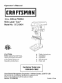
Operator's Manual
®
10 in. DRILL PRESS
With Laser Trac ®
Model No. 137.219001
CAUTION:
e
e
e
e
e
Before using this Drill Press,
read this manual and follow
all its Safety Rules and
Operating Instructions
Customer
Help
1-800-843-1682
Safety Instructions
Installation
Operation
Maintenance
Parts List
Line
Sears Brands Management
Corporation
Hoffman
Estates,
See the full line of Craftsman ® products at craftsman.com
Click on the Craftsman Club ®link and join today!
Part No. 137.219001001
IL 60179
USA
Printed in China
SECTION
PAGE
Warranty ...................................................
Product Specifications ..............................
Safety Guidelines - Definition ...................
Power Tool Safety .....................................
Drill Press Safety ......................................
Electrical Requirements And Safety ..........
Accessories And Attachments ...................
Tools Needed For Assembly .....................
Carton Contents ........................................
2
2
3
4
6
8
9
9
9
CRAFTSMAN
SECTION
Know Your Drill Press ................................
Glossary Of Terms ....................................
Assembly And Adjustments .......................
Operation ..................................................
Maintenaince .............................................
Troubleshooting Guide ..............................
Parts List ...................................................
Repair Protection Agreements ..................
PAGE
11
12
13
19
23
24
25
27
FULL WARRANTY
If this Craftsman product fails due to a manufacturer's defect in material or workmanship with one year from the
date of purchase, return it to any Sears store, Sears Parts & Repair Service Center, or other Craftsman outlet
in the United States for free free repair ( or replacement if repair proves impossible). This warranty does not
include expendable parts such as saw blades which can wear out from normal use within the warranty period.
This warranty applies for only 90 days from the date of purchase if this product is ever used for commercial or
rental purposes. This warranty gives you special legal rights, and you may also have other rights which vary
from state to state.
Sears, Roebuck and Co., Hoffman Estates, IL 60179
,_kWARNING
Some dust created by power sanding, sawing, grinding, drilling and other construction
activities contains
chemicals known to the state of California to cause cancer, birth defects or other reproductive
harm. Some
examples of these chemicals are:
- Lead from lead-based paints,
- Crystalline silica from bricks and cement and other masonry products, and
- Arsenic and chromium from chemically-treated lumber.
Your risk from these exposures varies, depending on how often you do this type of work. To reduce your
exposure to these chemicals: work in a well ventilated area, and work with approved safety equipment, such
as those dust masks that are specially designed to filter out microscopic particles. Avoid prolonged contact
with dust from power sanding, sawing, grinding, drilling, and other construction activities. Wear protective
clothing and wash exposed areas with soap and water. Allowing dust to get into your mouth, eyes, or lay on
the skin may promote absorption of harmful chemicals.
Chuck size ..........................................................................
1/2 in.
Speed ..................................................................................
Motor ...................................................................................
5 (620-3100 RPM)
6.0 A, 120 V, 60 Hz
2/3 HP (Max. Developed)
7-5/8 in. x 6-1/2 in.
Horsepower .........................................................................
Table Size ............................................................................
Table tilt ...............................................................................
Spindle travel .......................................................................
Throat ..................................................................................
Laser guide ..........................................................................
45 ° Right or Left
2 in.
5 in.
YES
, WARNING
To avoid electrical hazards, fire hazards or damages to the tool, use proper circuit protection.This
tool is wired
at the factory for 110-120 Volt operation. It must be connected to a 110-120 Volt / 6 Ampere
time delay fuse or circuit breaker. To avoid shock or fire, replace power cord immediately. If it is worn, cut or
damaged in any way.Before using your tool, it is critical that you read and understand these safety rules. Failure
to follow these
rules could result inserious injury to you or damage to the tool.
2
2010/10
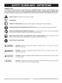
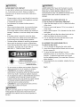
WARNING iCONS
Your power tool and its Operator's Manual may contain "WARNING iCONS" (a picture symbol intended to alert
you to and/or instruct you how to avoid a potentially hazardous condition). Understanding
and heeding these
symbols will help you operate your tool better and safer. Shown below are some of the symbols you may see.
A
SAFETY ALERT: Precautions that involve your safety.
®
O
PROHIBITION
WEAR EYE PROTECTION:
Always wear safety goggles or safety glasses with side shields,
WEAR RESPIRATORY AND HEARING PROTECTION:
Always wear respiratory and hearing protection.
READ AND UNDERSTAND OPERATOR'S MANUAL: To reduce the risk of injury, user and all bystanders
must read and understand operator's manual before using this product,
KEEP HANDS AWAY FROM THE MOVING PART AND CUTTING SURFACE: Failure to keep your hands
away from the moving part and cutting surface will result in serious personal injury,
SUPPORT AND CLAMP WORK
I,A DANGER
J
DANGER: Indicates an imminently
death or serious injury.
I,A WARNING
J
WARNING:
Indicates a potentially hazardous situation which, if not avoided, could result in
death or serious injury.
l_
i
CAUTION: Indicates a potentially hazardous situation which, if not avoided, may result in minor
or moderate injury.
CAUTION
i CAUTION
i
hazardous
situation which, if not avoided, will result in
CAUTION:
Used without the safety alert symbol indicates
which, if not avoided, may result in property damage.
potentially
hazardous
situation
10. USE PROPER EXTENSION CORDS. Make sure
GENERAL SAFETY INSTRUCTIONS
BEFORE USING THIS POWER TOOL
your extension cord is in good condition. When
using an extension cord, be sure to use one heavy
enough to carry the current your product will draw.
An undersized cord will result in a drop in line
voltage and in loss of power which will cause the tool
to overheat. The table on page 8 shows the correct
size to use depending on cord length and nameplate
ampere rating. If in doubt, use the next heavier
gauge. The smaller the gauge number, the heavier
the cord.
Safety is a combination of common sense, staying alert
and knowing how to use your power tool.
WARNING i
To avoid mistakes that could cause serious injury,
do not plug the tool in until you have read and
understood the following.
Read all instructions before operating product.
Failure to follow all instructions listed below may
result in electric
.
shock, fire and/or serious
11. WEAR PROPER APPAREL. Do not wear loose
injury.
clothing, gloves, neckties, rings, bracelets or other
jewelry which may get caught in moving parts.
Nonslip footwear is recommended. Wear protective
hair covering to contain long hair.
READ and become familiar with the entire
Instruction Manual. LEARN the tool's
application, limitations and possible hazards.
12.
2.
.
KEEP GUARDS IN PLACE and in working order.
REMOVE ADJUSTING
Any
powerWEAR
tool can
throw
foreign objects
LWAYS
EYE
PROTECTION.
into the eyes and could cause permanent
eye damage. ALWAYS wear Safety Goggles (not
glasses) that comply with ANSI Safety standard
Z87.1. Everyday eyeglasses have only impactresistant lenses. They ARE NOT safety glasses.
NOTE: Glasses or goggles not in compliance with
ANSI Z87.1 could seriously injure you when they
break.
O
KEYS AND WRENCHES.
Form the habit of checking to see that keys and
adjusting wrenches are removed from the tool before
turning ON.
4.
KEEP WORK AREA CLEAN. Cluttered areas and
benches invite accidents.
5. DO NOT USE IN DANGEROUS ENVIRONMENTS.
Do not use power tools in damp locations, or expose
13.
WEAR A FACE MASK OR DUST MASK.
Sawing operation produces dust.
them to rain or snow. Keep work area well lit.
14.
.
.
.
KEEP CHILDREN AWAY. All visitors and bystanders
should be kept a safe distance from work area.
MAKE WORKSHOP CHILD PROOF with padlocks,
master switches or by removing starter keys.
DO NOT FORCE THE TOOL. It will do the job better
and safer at the rate for which it was designed.
9. USE THE RIGHT TOOL. Do not force the tool or an
attachment to do a job for which it was not designed.
SECURE WORK. Use clamps or a vise to
hold work when practical. It is safer than
using your hand and it frees both hands to
operate the tool.
15. DISCONNECT
TOOLS FROM POWER SOURCE
before servicing, and when changing accessories
such as blades, bits and cutters.
16. REDUCE THE RISK OF UNINTENTIONAL
STARTING. Make sure switch is in the OFF position
before plugging the tool in.
17.USERECOMMENDED
ACCESSORIES.
ConsultthisInstruction
Manualforrecommended
accessories.
Theuseof improperaccessories
may
causeriskof injurytoyourselfor others,
18.NEVERSTANDONTHETOOL.Seriousinjury
couldoccurifthetoolis tippedor ifthecuttingtoolis
unintentionally
contacted,
21.DONOTOVERREACH.
Keepproperfootingand
balanceatalltimes.
22.MAINTAIN
TOOLS WITH CARE. Keep tools sharp
and clean for best and safest performance. Follow
instructions for lubricating and changing accessories.
23.DO NOT
use power tool in presence of flammable
liquids or gases.
19.CHECKFORDAMAGEDPARTS.Beforefurther
useofthetool,a guardorotherpartthatis damaged
shouldbecarefullycheckedtodetermine
thatitwill
operateproperlyandperformitsintendedfunction
- checkforalignment
of movingparts,bindingof
movingparts,breakage
ofparts,mountingand
anyotherconditions
thatmayaffectitsoperation.
Aguardorotherpartthatis damaged
shouldbe
properlyrepairedor replaced.
20.NEVERLEAVETHETOOLRUNNING
UNATTENDED.
TURNTHEPOWER"OFF".Donot
walkawayfroma runningtooluntilthebladecomes
toa completestopandthetoolis unplugged
from
thepowersource,
24.DO NOT
operate the tool if you are under the
influence of any drugs, alcohol or medicationn that
could affect your ability to use the tool properly.
25. Dust generated from certain materials can be
hazardous to your health. Always operate saw in
well-ventilated area and provide for proper dust
removal.
26.
WEAR HEARING PROTECTION to reduce
the risk of induced hearing loss.
l,&WAR.I.G
]
For your own safety, do not try to use your drill press or
plug it in until it is completely assembled and installed
according to the instructions, and until you have read and
understood this instruction manual:
.
CLAMP THE WORKPIECE OR BRACE IT against
the left side of the column to prevent rotation. If it is
too short or the table is tilted, clamp it solidly to the
table and use the fence provided.
13. IF THE WORKPIECE overhangs the table such that it
will fall or tip if not held, clamp it to the table or provide
auxiliary support.
securelyDRILL
to a workbench.
In addition,
if there
YOUR
PRESS MUST
BE BOLTED
is any tendency for your drill press to move
during certain operations, bolt the workbench to the
floor.
14. SECURE THE WORK. Use clamps or a vise to hold
the work when practical. It's safer than using your
hand and it frees both hands to operate tool.
THIS DRILL PRESS is intended for use in dry
conditions, indoor use only.
15. WHEN using a drill press vise, always fasten to the
table.
WEAR EYE PROTECTION.
16. MAKE SURE all clamps and locks are firmly
tightened before drilling.
,_
2.
.
USE a face or dust mask
along with safety goggles if drilling operation is dusty.
USE ear protectors, especially during extended
periods of operation.
4.
DO NOT wear gloves, neckties, or loose clothing.
17. SECURELY LOCK THE HEAD and table support to
the column, and the table to the table support before
operating the drill press.
5.
DO NOT try to drill material too small to be securely
held.
18. NEVER turn your drill press on before clearing the
table of all objects (tools, scraps of wood, etc.)
6. ALWAYS keep hands out of the path of a drill bit.
Avoid awkward hand positions where a sudden slip
could cause your hand to move into the drill bit.
19. BEFORE STARTING the operation, jog the motor
switch to make sure the drill bit does not wobble or
vibrate.
.
DO NOT install or use any drill bit that exceeds
175 mm (7 in.) in length or extends 150 mm (6 in.)
below the chuck jaws. They can suddenly bend
outward or break.
20. LET THE SPINDLE REACH FULL SPEED before
starting to drill. If your drill press makes an unfamiliar
noise or if it vibrates excessively, stop immediately,
turn the drill press off and unplug. If do not restart the
unit until the problem is corrected.
.
Q
cutters,
rotarybits,
planers
on
DO NOTcircle
USE (fly)
wirecutters,
wheels, orrouter
shaper
this drill press.
9. WHEN cutting a large piece of material, make sure it
is fully supported at the table height.
10. DO NOT perform any operation freehand. ALWAYS
hold the workpiece firmly against the table so it will
not rock or twist. Use clamps or a vise for unstable
workpieces.
11. MAKE SURE there are no nails or foreign objects in
the part of the workpiece to be drilled.
21. DO NOT perform layout assembly or set up work on
the table while the drill press is in operation.
22. USE THE RECOMMENDED SPEED for any drill
press accessory and for different workpiece
material. READ THE INSTRUCTIONS that come with
the accessory.
23.WHENDRILLINGlargediameterholes,clampthe
workpiece
firmlytothetable.Otherwise,
thebitmay
grapandspintheworkpiece
athighspeeds.DO
NOTUSEflycuttersor multiple-part
holecutters,as
theycancomeapartor becomeunbalanced
in use.
29. Drum sanders must never be operated on this drill
press at a speed greater than the speed rating of the
drum sander.
30.
Feed workpiece into a sanding drum or other
24.MAKE
SURE the spindle has come to a complete
stop before touching the workpiece.
25. TO AVOID INJURY from accidental starting, always
turn the switch "OFF" and unplug the drill press before installing or removing any accessory or attachment or making any adjustment.
approved accessory, against the direction of rotation.
31.
TYPE CHUCK
KEY as provided with the drill press.
WARNING
I
TO AVOID BEING PULLED INTO THE SPINNING
TOOL - Tie back long hair and roll long sleeves
above elbows.
IA wAR.I.Gl
A kickback occurs when workpiece suddenly binds
on the cutting edge of the tool and the workpiece is
thrown by the cutter in the direction of the cutter's
rotation. This can cause serious injury.
26. KEEP GUARDS IN PLACE and in working order.
27. USE ONLY THE SELF-EJECTING
IA wAR.I.Gl
32.
IA wAR.I.Gl
Do not allow familiarity (gained from frequent use of
your drill press) to become commonplace. Always
remember that a careless fraction of a second is
sufficient to inflict severe injury.
33. See page 18 for additional warnings on laser safety.
GROUNDINGINSTRUCTIONS
INTHE EVENT OF A MALFUNCTION
OR
(When using 120 volts only)
BREAKDOWN, grounding provides a path of least
resistance for electric current and reduces the risk of
Ampere
more than
shock. This tool is equipped with an electric cord that
has an equipment grounding conductor and grounding
plug. The plug MUST be plugged into a matching
receptacle that is properly installed and grounded in
accordance with ALL local codes and ordinances.
Rating
not more than
25ft.
Total Length of Cord
50ft.
100ft.
150ft.
0
6
18
16
16
14
10
12
16
12
16
14
16
14
12
12
not recommended
Make sure your extension cord is in good condition.
When using an extension cord, be sure to use one
heavy enough to carry the current your product will
draw. An undersized cord will cause a drop in line
voltage resulting in loss of power and overheating. The
table above shows the correct size to use according to
cord length and nameplate ampere rating. If in doubt,
use the next heavier gauge. The smaller the gauge
number, the heavier the cord.
DO NOT MODIFY THE PLUG PROVIDED. If it will not
fit the receptacle, have the proper receptacle installed
by a qualified electrician.
iMPROPER CONNECTION of the equipment grounding
conductor can result in risk of electric shock. The
conductor with the green insulation (with or without
yellow stripes) is the equipment grounding conductor.
If repair or replacement of the electric cord or plug is
necessary, DO NOT connect the equipment grounding
conductor to a live terminal.
Be sure your extension cord is properly wired and
in good condition. Always replace a damaged extension
cord or have it repaired by a qualified person before
using it. Protect your extension cords from sharp
objects, excessive heat and damp or wet areas.
CHECK with a quail ed electrician or service personnel
Use a separate electrical circuit for your tools. This
circuit must not be less than #12 wire and should
if you do not completely understand the grounding
instructions, or if you are not sure the tool is properly
grounded.
USE ONLY 3=WIRE EXTENSION CORDS THAT
HAVE 3=PRONG GROUNDING PLUGS AND 3=POLE
be protected with a 15 Amp time lag fuse. Before
connecting the motor to the power line, make sure the
switch is in the OFF position and the electric current is
rated the same as the current stamped on the motor
nameplate. Running at a lower voltage will damage the
motor.
RECEPTACLE THAT ACCEPT THE TOOL'S PLUG.
REPAIR OR REPLACE DAMAGED OR WORN CORD
IMMEDIATELY.
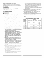
3-Prong Plug
This tool is intended for use on a circuit that has a
receptacle like the one illustrated in FIGURE A.
FIGURE A shows a 3-prong electrical plug and
receptacle that has a grounding conductor. If a properly
grounded receptacle is not available, an adapter
(FIGURE B) can be used to temporarily connect this
plug to a 2-contact ungrounded receptacle. The adapter
(FIGURE B) has a rigid lug extending from it that MUST
be connected to a permanent earth ground, such as a
properly grounded receptacle box. THE TEMPORARY
ADAPTER SHOULD BE USED ONLY UNTIL A
PROPER GROUNDED OUTLET CAN BE INSTALLED
BY A QUALIFIED ELECTRICIAN.
FIGURE A
g Prong
Properly Grounded
3-Prong Receptacle
FIGURE B
Grounding Lug
/ I(_
Make Sure This is
¢_t _, l_4J,<_- Connected to a
__.
S
GUIDELINES
_')_-Ad_a_
t_r_
P
I! Known Ground
CAUTION: In all cases, make certain the receptacle in
question is properly grounded, If you are not sure, have
a certified electrician check the receptacle,
I_-:cr°pgacle
FOR EXTENSION
CORDS
{,_WARNING
[a,WARNING
I
1
This drill press is for indoor use only, Do not expose to
rain or use in damp locations,
This tool must be grounded while in use to protect the
operator from electrical shock.
8
RECOMMENDED
[,_WARNING
ACCESSORIES
UNPACKING
AND CHECKING
CONTENTS
,&WARNING I
J
Use only accessories recommend for this drill press.
Ifany partismissingor damaged, do notplugthedrill
Follow instructions that accompany accessories, Use of
improper accessories may cause hazards,
press inuntil
themissingor damaged partisreplaced,
and assembly iscomplete.ContacttheCustomer Help
Lineat1-800-843-16828:30AM-5:00 PM EST
Visit your Sears Hardware Department or see the Sears
Power and Hand Tool Catalog for the follow accessories:
• Drill bits
•
•
Monday-Fridayformissingparts.
Carefully unpack the drill press and all its parts, and
compare against the list below.
Hold-Down Clamps
Drill press Vises
To protect the drill press from moisture, a protective
coating has been applied to the machined surfaces.
Remove this coating with a soft cloth moistened with
kerosene or WD-40.
[ WAR"I"GI
Use only acessories designed for this drill press to
avoid injury from thrown broken parts or workpieces.
,_WARNING
Sears may recommend other accessories not listed in
this manual. See your nearest Sears store or Power and
Hand Tool Catalog for other accessories.
To avoid fire or toxic reaction, never use gasoline,
naphtha, acetone, lacquer thinner or similar highly
volatile solvents to clean the drill press.
Do not use any accessory unless you have completely
read the instruction or operator's manual for that
Apply a coat of paste wax to the table, column and
machined surfaces of base to prevent rust. Wipe
all parts thoroughly with a clean dry cloth.
accessory.
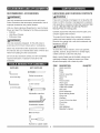
SUPPLIED
NOT SUPPLIED
Slotted screwdriver
3 mm hex key
,,
4 mm hex key
12 mm wrench
_
(O_
Adjustable wrenches
Combination
¢
square
¢
Block of wood
Hammer or rubber mallet
9
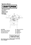
ITEM
DESCRIPTION
QUANTITY
A.
B.
C.
Head assembly
Base
Table
1
1
1
D.
E.
F.
G.
Column assembly
Rack ring
Rack
Feed handles
1
1
1
3
H.
I.
J.
K.
Worm gear
Table crank handle
Table lock handle
Hex bolts
1
1
1
3
L.
M.
N.
O.
Fence assembly
Fence locking knobs
Wing nuts
Washers
1
2
2
4
P.
Q.
R.
S.
3 mm & 4 mm hex keys
Chuck key
Chuck
AAA batteries
2
1
1
2
T.
Operator's manual
1
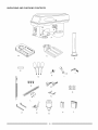
UNPACKING
AND CHECKING
CONTENTS
A
C
D
E
J
H
G
O
N
L
P
Q
$
R
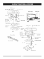
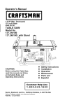
Depthstopnuts
Beltspeedsightwindow
Depthscalepointer
Spindle pulley
Motor pulley
Depth scale
Quillreturn
coil/ spring
Feed handle
Spindle
Rack ring
_
Table bracket
Table lock
handle
Pulley cover
Belt speed sight window
Bevel lock bolt
Chuck key
holder
",
Base
ON/OFF
switch with
Belt tension
lock knob
safety key
Fence endstop
Laser guide
Head locking screw
Chuck
Bevel scale
Table crank handle
Table
Column
Rack
Mounting holes
11
BASE- Supportsdrillpress.Foradditionalstability,
holesareprovidedinbaseto boltdrillpressto
workbench.
HEADLOCKING
SCREWS
- Lockstheheadtothe
column.ALWAYSlockheadin placewhileoperatingthe
drillpress.
BACKUPMATERIAL
- A pieceofscrapwoodplaced
betweentheworkpieceandtable.Thebackupboard
prevents
woodintheworkpiece
fromsplintering
when
thedrillpassesthroughthebacksideoftheworkpiece.It
alsopreventsdrillingintothetabletop.
ON/OFFSWITCH
- Incorporates
a safetyswitch
keywhichcanberemovedto preventaccessfrom
unauthorized
users.Insertthe keyintotheswitchtoturn
thedrillpresson.
PULLEYCOVERASSEMBLY- Coversthepulleysand
beltduringoperationofthedrillpress.
BELTTENSION
- Refertothe"Assembly"
Section,
"InstallingandTensioning
Belt".
RACK- Combines
withgearmechanism
toprovide
easyelevationofthetablebythetablecrankhandle.
BELTTENSIONLOCKKNOB- Locksthemotor
bracketsupportmaintaining
correctbeltdistanceand
tension.
BEVELSCALE- Showsdegreeoftableangleforbevel
operations.
Scaleis locatedbehindthetable.
RACKRING- Holdstherackto thecolumn.Rack
remainsmovableinthecollartopermittablesupport
movements.
Alwayscheckthatringistightbefore
startinganyoperation,
CHUCK- Holdsa drillbitorotherrecommended
accessory
to performdesiredoperations.
REVOLUTIONS
PERMINUTE(R.P.M)- Thenumber
ofturnscompleted
by a spinningobjectinoneminute.
CHUCKKEY- A self-ejecting
chuckkeyis provided
anddesignedto popoutofthechuckwhenyouletgoof
it.Thisactionis designedto helppreventthrowingofthe
chuckkeyfromthechuckwhenthepoweristurnedON.
Donotuseanyotherkeyas a substitute,ordera new
oneifdamaged
or lost.
SPINDLESPEED- TheR.P.M.ofthespindle.
COLUMN- Connectsthehead,table,andbaseona
onepiecetubeforeasyalignment
andmovement.
TABLEBEVELLOCKBOLT- Locksthetableinany
positionfrom0°- 45°.
DEPTHSCALE-Indicatesdepthofholebeingdrilled.
Scaleis locatedonleftsideofdrillhead.
TABLECRANKHANDLE- Elevatesandlowerstable.
Supportlockhandlemustbereleasedbeforeoperating
crank.
SPRINGCAP- Adjuststhequillreturnspringtension.
TABLE- Providesa workingsurfacetosupportthe
workpiece.
DEPTHSCALESTOPNUTS- Canbeadjustedtostop
thequillforcertaindepthdrillingoperations.
TABLESUPPORT
LOCKHANDLE- Tightening
locks
thetablesupporttothecolumn.Alwayshaveit lockedin
placewhileoperatingthedrillpress.
DRILLBIT- Thecuttingtoolusedinthedrillpressto
makeholesina workpiece.
TABLEBRACKET- Ridesonthecolumntosupport
thetable.
DRILLINGSPEED- Changedbyplacingthebeltin any
of thesteps(grooves)inthepulleys.SeetheSpindle
SpeedChartinsidebeltguard.
WORKPIECE
- Materialbeingdrilled.
FEEDHANDLE- Movesthechuckupor down.One
or twoof thehandlesmayberemovedifnecessary
whenever
theworkpiece
is ofsuchunusualshapethatit
interferes
withthe handles.
FENCE- Attachestothetableto aligntheworkpiece
or forfastrepetitivedrilling.Removefencewhenit
interferes
withotherdrillpressaccessories.
12
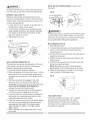
ASSEMBLY
INSTRUCTIONS
Fig. B
[ WARNING
I
Foryourown safety,
never connectplugtopower
sourceoutletuntil
allassemblystepsarecompleteand
you have read and understoodthesafetyand operating
instructions.
1
3
[,AWARNING
I
The drill
pressisa heavy power tooland shouldbe
lifted
withthehelpoftwo PEOPLE OR MORE tosafely
assemble it,
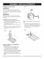
ASSEMBLING
COLUMN TO BASE (FIG. A)
1. Position the base (2) on a flat, stable worksurface
(must be able to support 100 Ibs.).
2. Place the column (1) on the base, aligning the three
mounting holes to the base.
NOTE: Table removed from bracket in illustration for
clarity.
,
3. Locate the three hex bolts (3) from the loose parts
bag.
4. Place a bolt in each hole through the column support
and thread into the base. Tighten with a 12 mm
wrench.
Place the rack (5)inside the table bracket (3) as
shown in Fig. C, making sure the worm gear (1) on
the inside of the table bracket is engaged with the
teeth of the rack and the arrow stamped on the
rack is pointing up.
Fig. C
Fig. A
3
INSTALLING
TABLE TO COLUMN ASSEMBLY
(FIG. B THROUGH F)
1. Install the table lock handle (4) into the hole
at the rear of the table bracket. NOTE: install
the handle from left to right, so it enters the
non-threaded side of the table bracket first.
2. insert the worm gear (1) into the table crank handle
hole (2) from inside the table support (3). Make sure
the worm gear (1) meshes with the inside gear.
NOTE: Do not remove the lubrication from this worm
gear.
13
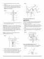
,
Slide this table assembly with the rack onto the
column.
Fig. F
5. Engage the bottom of the rack (5) with the lip of the
column support (6). Tighten the table bracket lock
10
handle (4) to lock the table assembly to the column,
NOTE: Do not overtighten.
®
©
11
12
_5
INSTALLING
THE HEAD (FIG. G)
wAR.I.G t
,
The Drill Press head is heavy and should be lifted with
the help of two PEOPLE to safely assemble the drill
press head on the column.
Install the rack ring (7) on the column so the top lip of
the rack sits into the rack ring,
IMPORTANT:
1. Carefully lift the head (1) and slide it into the top of
column (2). Make sure the head slides down over the
The bottom of the collar MUST NOT be
pushed all the way down onto the top of the rack. MAKE
SURE the top of the rack is under the bottom of the
collar and that there is enough clearance to allow the
rack to freely rotate around the column. Tighten the set
column as far as possible. Align the head with the
base.
2. Using the 4 mm hex wrench provided, tighten the two
head locking setscrews (3) on the right side of the
head.
screw (8) using the 3 mm hex wrench.
Fig. G
NOTE: To avoid column or collar damage, DO NOT
OVERTIGHTEN the set screw.
Fig. E
5
INSTALLING FEED HANDLES (FIG. H)
1. Screw the three feed handles (1) into the threaded
holes (2) on the hub assembly (3) and tighten,
Fig. H
7. Install the table crank handle (9) onto the worm gear
shaft (11) on the side of the table support (12).
8. Line up the flat side of the shaft with the set screw (10)
in the crank handle and tighten the screw with the
3 mm hex wrench provided, Do not overtighten.
14
iNSTALLiNG THE CHUCK (FIG. I, J AND K)
I,A
[,_WARNiNG
RISK OF PROPERTY DAMAGE. To avoid damage to
the chuck, NEVER drive the chuck on the spindle with
a metal hammer.
]
Before any assembly or the chuck to the drill press head,
clean all mating surfaces with a non-petroleum based
product. Any oil or grease used in the packing of these
parts must be removed otherwise the chuck may come
loose during operation.
,_WARNING
CAUTION]
Fig. K
1
To avoid injury from an accidental start, ALWAYS make
sure the power switch is in the "OFF" position, the
switch key is removed, and the plug is not connected to
the power source outlet before removing or installing
the chuck.
.
.
Clean out the tapered hole in the chuck (1) with a
clean cloth and a non-alcohol based cleaner. Wipe
REMOVING THE CHUCK
1. Turn the feed handles to lower the chuck to the
clean all oil reside and any dirt or grime thoroughly.
Clean tapered surfaces on the spindle (2)in the
same manner as above.
lowest position.
2. Place a ball joint separator (not shown) above the
chuck and tap it lightly with a hammer or rubber
mallet to cause the chuck to drop from the spindle.
NOTE: Never hit the chuck directly with the hammer
or rubber mallet.
NOTE: Make sure there are no foreign particles
sticking to the surfaces. The slightest piece of dirt or
oil reside on any of these surfaces will prevent the
chuck from seating properly. This will cause the drill
chuck and bit to wobble.
NOTE: The avoid possible damage to the chuck, raise
the jaws all the way first and be prepared to catch the
chuck as it falls.
Fig. I
MOUNTING
(FIG. L)
1. If mounting the drill press to a workbench, a solid
wood bench is preferred over a plywood board, to
reduce noise and vibration.
2
.
DRILL PRESS TO WORK SURFACE
2. Holes should be pre-drilled through the supporting
surface.
Open the jaws of the chuck (1) by rotating the chuck
sleeve clockwise. To prevent damage, make sure the
3. The hardware to mount this drill press is NOT
supplied with the tool. The hardware as shown in the
illustration should be used:
jaws are completely receded into the chuck.
Fig. J
Fig. L
1. Drill press base
2. Bolt
3. Flat washer
2
1
4. Rubber washer
5. Worksurface
6. Flatwasher
7. Lockwasher
8. Hex nut
9. Jam nut
4. Unlock the table support lock (4- Fig. D) and swing
i i
the table away from the bottom of the chuck.
5. Insert the chuck onto the spindle, pushing upwards
all the way.
__
6. Using a rubber mallet or a hammer and a block of
wood, tap the chuck onto the spindle firmly (Fig. K).
_6
15
_E
i i
I!
EE
"_E
I!
/1
CHUCKKEYSTORAGE
(FIG.M)
To protect the drill press from moisture, a protective
coating has been applied to the machined surfaces.
Remove this coating with a soft cloth moistened with
kerosene or WD-40.
Storage holder (1) for the chuck key (2) is located on the
right side of the drill press,
Fig. M
ADJUSTMENT
INSTRUCTIONS
NOTE: All the adjustments for the operation of the
drill press have been completed at the factory. Due to
normal wear and use, some occasional readjustments
may be necessary.
,,AWARNING
To avoid injury from an accidental start, ALWAYS make
ASSEMBLING FENCE (FIG. N, N-1 )
1. Assembling the fence back stop (1) and the end
stop (2) with a bolt (3) and a wing nut (4).
Fig. N
sure the switch is in the "OFF" position, the switch key
is removed, and the plug is not connected to the power
source outlet before making belt adjustments.
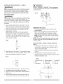
BEVEL DRILLING (FIG. O)
3
NOTE: A bevel scale has been included to measure
approximate bevel angles. If precision is necessary,
a square or other measuring tool should be used to
2
position the table. To use the bevel scale (6):
1. TIGHTEN the nut (4) on the locking pin using a
10 mm or adjustable wrench clockwise to RELEASE
the pin from its table support. This pin will be needed
when placing the table back to its 0 degree setting
from the table support, do not throw away.
2. Loosen the large hex head table bevel locking bolt (5)
using a 17 mm or adjustable wrench.
4
2. Align the mounting holes of the fence over the table
slots.
3. Place a washer (5) on the threaded end of the knob
(6). Insert the knob through the mounting hole of the
fence and the table slot.
3. Tilt the table, aligning the desired angle measurement
to the zero line opposite the scale (6).
4. Tighten the table bevel locking bolt (5).
4. Place a washer and wing nut (7) on the knob from
under the table.
5. Repeat for the other knob and tighten.
5. To return the table to its original position, loosen the
table bevel locking bolt (5). Return the table (6) to the
0° position.
Fig. N-1
6. Return nut (4) on locking pin to the OUTSIDE END
OF THREADS. Gently tap locking pin, using a rubber
mallet, until it is seated in the mating hole of the table
bracket. Hand tighten nut (4).
NOTE: The table has been removed from the
illustration for clarity.
Fig.O
7
NOTE: Before operating the drill, make sure no
part of the fence is touching the drill bit or drill
chuck. When the fence is not being used, remove
completely from the table.
16
[,AWARNING
l
NOTE: DO NOT OVERTIGHTEN
movement.
and restrict quill
To prevent personal injury, always disconnect the plug
from the power source when making any adjustments.
SPINDLE / QUILL (FIG. P)
Rotate the feed handles counterclockwise
to lower
spindle to its lowest position. Hold the chuck and move
it front to back. If there is excessive play, proceed with
Fig. Q
_4
the following adjustments:
1. Loosen the lock nut (1) located on the right side of
the drill press, using a 10 mm wrench.
2. Turn the screw (2) clockwise to eliminate the play,
using a slotted screwdriver, but without obstructing
the upward movement of the the spindle. (A little
play in the spindle is normal.)
3. Tighten the lock nut (1).
,A.WARNING
1
To avoid injury from
sure the switch is in
is removed, and the
source outlet before
Fig. P
an accidental start, ALWAYS make
the "OFF" position, the switch key
plug is not connected to the power
making belt adjustments.
BELT TENSION (FIG. R)
1. Open the pulley cover.
2. To unlock the belt tension, turn the belt tension lock
knob (1) on the right side of the drill press head
counterclockwise.
3. Pull the motor (2) toward the front of the drill press to
loosen the belt tension.
4. Position the belt on the correct pulley steps for the
desired speed.
QUILL RETURN SPRING (FIG. Q)
The quill return spring may need adjustment if the quill
5. Push the motor away from the drill press head until
the belt is properly tensioned.
NOTE: Belt tension is correct if the belt deflects
return speed is too rapid or too slow. This spring is
located on the left side of the drill head.
approximately 1/2 inch when pressed at its center.
6. Tighten the belt tension lock knob (1) to secure the
motor in position. Close pulley cover.
1. Lower the table for additional clearance.
2. Place a screwdriver
in the lower front notch (1) of the
spring cap (2). Hold it in place while loosening and
removing only the outer jam nut (3), using a 10 mm
wrench.
Fig. R
3. With the screwdriver still engaged in the notch,
loosen the inner nut (4) just until the notch (5)
disengages from the boss (6) on the drill press head.
NOTE: DO NOT REMOVE THIS INNER NUT,
because the spring will forcibly unwind.
J2
4. Carefully turn the spring cap (2) counterclockwise
with the screwdriver, engaging the next notch.
5. Lower the quill to the lowest position by rotating the
feed handle in a counterclockwise direction while
THE LASER TRAC ®
Your tool is equipped with Laser Trac ® , a battery
powered device using Class Ilia laser beams.
The laser beams will enable you to preview the
holding the spring cap (2)in position.
6. If the quill moves up and down as you desire, tighten
the inner nut (4) sung against the spring cap and
spring cap with the wrench. If too loose, repeat
steps 3 through 5 to tighten, if too tight, reverse
steps 4 and 5.
7. Secure the outer nut (3) against the inner nut with
the wrench.
drill bit path on the workpiece to be drilled before
you begin your operation.
17
[ WAR"ING
1
,_WARNING
AVOID DIRECT EYE CONTACT
LASER RADIATION. Never aim the beam at a work
piece with a reflective surface. Bright shiny reflective
sheet steel or similar reflective surfaces are not
recommended for laser use. Reflective surfaces could
direct the beam back toward the operator or by
standers.
A Laser light is radiated when the laser guide is turned
on. Avoid direct eye contact. Always un-plug the
drill press from the power source before making any
adjustments.
,
A laser pointer is not a toy and should not come into
hands of children. Misuse of this appliance can lead
to irreparable eye injuries.
Any adjustment to increase the laser power is
forbidden.
,
1
ADJUSTING
THE LASER LINES (FIG. S)
A. How to check the Laser=beam Alignment?
1. Adjust the table height so it is 5 in. below the bottom
of the chuck.
When using the laser pointer, do not point the laser
beam towards people and/or reflecting surfaces.
2. Scribe a round circle (approx. 1/8 in.) on a piece of
scrap wood.
3. Insert a drill bit approx 1/8 in. diameter into the chuck
Even a laser beam of lower intensity may cause eye
damage. Therefore, do not look directly into the laser
beam.
and tighten.
4. Lower the quill and align the scribed circle with the
drill bit and fasten the wood to the table.
-
If the laser pointer is stored for more than three
5. Turn on the laser and verify the laser lines (x) are
centered onto the scribed circle.
-
months without use, please remove the batteries to
avoid damage from possibly leaking batteries.
The laser pointer includes no servicing components.
•
Never open the housing for repair or adjustments.
Laser Warning label: Max output <5mW Wavelength:
B. ALIGNING THE LASER=BEAM (FIG. S)
To adjust the laser lines:
1. Turn on the laser by pressing the rocker switch.
630-660nm, Complies with 21CFR 1040.10
and 1040.11. Class Ilia Laser Product.
f
2. Lower the drill press quill and loosen one turn each
the four screws (4).
3. To adjust the laser beam left/right, turn the
...................................................................................................................................................................................................................................................................................................
adjustment screw (1) no more than 1/8 turn in either
direction. To adjust the laser beam front to back,
turn the adjusting screw (2) no more than 1/8 turn in
either direction.
LASER RADIATION-AVOID
DIRECT EYE EXPOSURE
4. Once adjustments are completed, retighten the four
screws (4).
Max.Output <5 mWWavelength: 630-660 nm
Complieswith 21 CFR1040.10and 1040.11
Class Ilia Laser Productj
•
•
•
Fig. S
Do not remove or deface warning labels. Removing
labels increases the risk of exposure to radiation.
CAUTION=Use of controls or adjustments or
performance of procedures other than those specified
herein may result in hazardous radiation exposure.
Do not attempt to repair or disassemble the laser level.
If unqualified persons attempt to repair this laser
product, serious injury may result. Any repair required
on this laser product should be performed by
authorized service center personnel.
CAUTION=The use of optical instruments with this
product will increase eye hazard.
4
[,4kWARNINGI
DO NOT use tinted glasses to enhance the laser light.
Tinted glasses will reduce the overall vision for the
application and interfere with the normal operation of
the tool.
18
BASIC
DRILL PRESS
OPERATIONS
,AWARNING
ALWAYS lock the switch "OFF" when the drill press is
not in use by removing the safety switch key keep it in a
NOTE: This machine incorporates view windows on the
pulley cover used to observe the location of the belt.
[_WARNING
I
safe place. In the event of a power failure, blown fuse,
or tripped circuit breaker, turn the switch "OFF" and
remove the key, preventing an accidental startup when
]
To avoidpossibleinjury,
keep guard closedand inplace
power comes on.
while tool is in operation.
Fig.U
SPEEDS AND BELT PLACEMENT (FIG. T)
This drill press has five operating speeds. Fig. T shows
each speed and the placement of the belt to obtain those
speeds. This chart is also located in the inside pulley
guard for reference.
Fig. T
620 RPM
1100RPM
1720RPM
INSTALLING DRILL BIT IN CHUCK (FIG. V)
1. With the switch "OFF" and the safety key removed,
open the chuck jaws (1) using the chuck key (2). Turn
2340RPM
the chuck key counterclockwise to open the chuck
jaws (1).
2. Insert the drill bit (3) into the chuck far enough to
obtain maximum gripping by the jaws, but not far
3100RPM
enough to touch the spiral grooves (flutes) of the drill
bit when the jaws are tightened.
3. Make sure that the drill is centered in the chuck.
NOTE: See the DRILLING SPEED TABLE (RPM) on
page 21 for size of drill bit and material drilling
recommendations.
4. Turn the chuck key clockwise to tighten the jaws.
,,AWARNING
I
To avoid injury or accident by the chuck key ejecting
forcibly from the chuck when the power is turned "ON",
use only the self-ejecting chuck key supplied with this
ON/OFF SWITCH (FIG. U)
The ON / OFF switch has a removable, safety key.
With the key removed from the switch, unauthorized
drill press. ALWAYS recheck and remove the chuck key
before turning the power "ON". Place the chuck key into
and hazardous use by children and others is minimized.
1. To turn the drill press "ON", insert key (2) into the slot
of the switch (1). Move the switch upward to the "ON"
position.
2. To turn the drill press "OFF", move the switch
downward.
its storage holder when not in use.
Fig. V
3. To lock the switch in the OFF position, grasp the
sides of the safety key, and pull it out.
4. With the safety key removed, the switch will not turn
the power tool on.
5. If the safety key is removed while the drill press
2
is running, it can be turned "OFF" but cannot be
restarted without inserting the safety key.
1
3
19
USINGTHEFENCE(FIG.W)
Thefenceprovidesa wayofaccuratelyandquickly
settinguptheworkpiece
forprecision
or forrepetitive
drillingoperations.
1. Usinga centerpunch
or sharpnail,makean
indentation
intheworkpiece
whereyouwantto drill.
2. Alignthelaserlines(x)withthe indentation
onthe
workpiece.
3. Loosentheknobs(1)andslidethefencebackstop(2)
firmlyagainstthe longsideoftheworkpiece.
Tighten
theknobswhenin position.
4. Loosenthewingnut(3)andslidetheendstop(4)
alongthefenceuntilitis firmlyagainsttheleftsideof
theworkpiece.
Tightenthewingnut.
5. Checktheaccuracybydrillingintoa scrapworkpiece
first.Adjustif needed.
6. Holdwithyourhandor clampthetopsurfaceofthe
workpiece
firmlyto preventitfromliftingoffthetable
whenthebitis raised.
Fig.W
Fig.X
Depthscalemethod(Fig.Y)
Note:Withthechuckin theupperposition,thetip of
thedrillbit mustbejustslightlyabovethetopofthe
workpiece.
1. Withtheswitch"OFF",turnthefeedhandleuntilthe
pointer(7)pointstothedesireddepthonthedepth
scale(4)andholdthefeedhandleinthatposition.
2. Spinthelowernut(3)downtocontactthedepthstop
lug(6).
3. Spintheuppernut(5)againstagainstthelowerstop
nutandtighten.
4. Thedrillbitwillstopaftertravelingthedistance
selectedonthedepthscale.
Drill a hole
3 4
Using a center punch or a sharp nail, make an
indentation in the workpiece where you want to drill.
Turn on the laser assembly and align the laser lines (x)
with the indentation. Turn the power switch on and pull
down on the feed handles with only enough effort to
allow the drill to cut.
FEEDING TOO RAPIDLY might cause the belt or drill
to slip, tear the workpiece loose, or break the drill bit.
When drilling metal, it will be necessary to lubricate the
tip of the drill bit with metal drilling oil to prevent it from
overheating.
DRILLING
TOA SPECiFiCDEPTH
Drillinga blindhole(notallthewaythroughworkpiece)
to a givendepthcanbedonetwoways:
Workpiecemethod(Fig.X andY)
1. Markthedepth(1)oftheholeonthesideofthe
workpiece(Fig.X).
2. Withtheswitch"OFF",bringthedrillbit (2)downuntil
thetip is evenwiththemark(Fig.X)
3. Holdthefeedhandleatthisposition.
4. Spinthelowernut(3)downtocontactthedepthstop
lug(6)onthehead(Fig.Y).
5. Spintheuppernut(5)downandtightenagainstthe
lowernut(3)(Fig.Y).
6. Thedrillbitwillnowstopaftertravelingthedistance
markedontheworkpiece.
Fig. Y
-L
4
6
2O
BASICOPERATING
INSTRUCTIONS
Togetthebestresultsandminimizethelikelihood
of
personalinjury,followtheseinstructions
foroperating
yourdrillpress.
j.
the panel on the inside pulley cover or the chart
below for drilling speed information. For
accessories, refer to the instructions provided with
each accessory.
[ WARNING
I
For your own safety, always read the SAFETY
INSTRUCTIONS listed within this operator's manual.
4. Never climb on the drill press table, it could break or
pull the entire drill press down on you.
5. Turn the power switch "OFF", and put away the
FOR YOUR PROTECTION
safety key when leaving the drill press.
6. To avoid injury from thrown work or tool contact, do
not perform layout, assembly, or setup work on the
I
To avoid being pulled into the power tool, do not wear
loose clothing, gloves, neckties, or jewelry. Always tie
table while the cutting tool is rotating.
back long hair.
1. If any part of your drill press is missing,
Fig. Z
malfunctioning, damaged or broken, stop operation
immediately until that part is properly repaired or
replaced.
2. Never place your fingers in a position where they
DRILLING
Drill Bit
Diameter
(Inches)
1/16
1/8
3/16
1/4
5/16
3/8
1/2
could contact the drill bit or other cutting tool. The
workpiece may unexpectedly shift, or your hand
could slip.
3. To prevent the workpiece from being torn from your
hands, thrown, spun by the tool, or shattered, always
properly support your workpiece as follows:
a.
b.
c.
Always position BACKUP MATERIAL (used
beneath workpiece ) so that it contacts the left
side of the column, or use the fence provided and
a clamp to brace the workpieces.
Whenever possible, position the workpiece to
contact the left side of the column. If it is too short
or the table is tilted, use the fence provided or
clamp solidly to the table, using the table slots.
When using a drill press vise, always fasten it to
the table.
d. Never do any work freehand (hand-holding the
workpiece rather than supporting it on the table),
except when polishing or sanding.
e. Securely lock the head and support to the column,
the table arm to the support, and the table to the
table arm, before operating the drill press.
f. Never move the head or the table while the tool is
running.
g. Before starting an operation, jog the motor switch
to make sure the drill or other cutting tool does
not wobble or cause vibration.
h. If a workpiece overhangs the table so it will fall or
tip if not held, clamp it to the table or provide
i.
Use the SPINDLE SPEED recommended for the
speci c operation and workpiece material. Check
auxiliary support.
Use fixtures for unusual operations to adequately
hold, guide, and position workpiece.
21
SPEED
TABLE
Wood
Material
Alum., Zinc., Brass
3100
3100
(RPM)
Iron, Steel
3100
2340
1720
2340
1100
2340
1720
1100
620
POSiTiONiNG
THETABLEANDWORKPIECE
(FIG.AA AND BB)
2. Turn the laser "ON" and align the laser lines (x) with
1. Lock the table (1) to the column (2) at a position so
the tip of the drill bit (3) is just above the top of the
TILTING THE TABLE (FIG. CC)
the indentation before turning the drill ON.
NOTE: The table arm and support (1) has a predrilled
hole with a locking pin inserted for locking the table into
workpiece (4).
2. ALWAYS place a BACK-UP MATERIAL (scrap wood)
on the table beneath the workpiece. This will prevent
splintering or heavy burring on the underside of
a predrilled 0 ° bevel angle.
1. TIGHTEN the nut (4) on the locking pin using a
10 mm or adjustable wrench clockwise to RELEASE
the pin from its table support. This pin will be needed
when placing the table back to its 0 degree setting
from the table support.
the workpiece. To keep the back-up material from
spinning, it MUST be positioned against the LEFT
side of the column.
3. For a small piece that cannot be clamped to the
table, use a drill press vise (optional accessory).
2. Loosen the large hex head table bevel locking bolt (3)
using a 17 mm or adjustable wrench.
[a,
WARNING
I
[ WARNING
I
To preventtheworkpieceor backup material
from being
thrownwhiledrilling,
you MUST position
theworkpiece
againstthe LEFT sideofthecolumn. Iftheworkpiece
To preventinjury,
be sureto holdthetable& tablearm
assembly, so it will not swivel or tilt.
Fig. CC
or thebackup material
isnotlongenough to reach
thecolumn,clamp them tothetable,
or use thefence
providedwiththedrill
pressto bracetheworkpiece.
4
Failure
tosecuretheworkpiececouldresult
inpersonal
injury.
Fig. AA
3. Tilt the table, aligning the desired angle measurement
to the zero line opposite the scale (4).
4. Tighten the table bevel locking bolt (3).
5. To return the table to its original position, loosen the
table bevel locking bolt (3). Return the table (1) to the
0° position.
6. Return nut (2) on locking pin to the OUTSIDE END
[ WARNING I
A drill
pressviseMUST
OF THREADS. Gently tap locking pin until it is
seated in the mating hole of the table bracket. Hand
be clamped orboltedtothe
tabletoavoidinjury
from a spinningworkpiece,or
damaged viseor bitparts.
tighten nut (2).
,_I_WARNING
Remove thedrill
pressfence when itinterferes
with
otherdrill
pressaccessories.
To avoid injury from spinning work or tool breakage,
always clamp workpiece and backup material securely
to the table before operating the drill press.
Fig. BB
FEEDING
1. Pull down the feed handles with only enough effort to
allow the drill bit to cut.
2. Feeding too slowly might cause the drill bit to burn.
Feeding too rapidly might cause the belt or drill to
slip, tear the workpiece loose or break the drill bit.
HOLDING A DRILLING LOCATION
3. When drilling metal, it is necessary to lubricate the
drill bit tip with oil to prevent burning of the workpiece
and bit.
1. Using a centerpunch or sharp nail, make an
indentation in the workpiece where you will be
drilling.
22
,_ WARNING
Fig. DD
1
For your own safety, turn the switch OFF and remove
the plug from the power source outlet before maintaining
or lubricating your drill press.
Frequently blow out, using an air compressor or dust
vacuum, any sawdust or metal chips that
accumulates inside the motor, pulley housing, table
and work surface. Always wear protective safety goggles.
[ WARNING
I
To avoid shock or fire hazard, if the power cord is worn
or cut in any way, have it replaced immediately by a
HELPFUL HINT: Remove the two batteries during long
periods of non-use of the drill. This will reduce damage
to the laser guide from the batteries corroding during
storage.
qualified electrician or service technician.
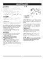
LUBRICATION
All of the drill press ball bearings are packed with grease
at the factory. They require no further lubrication.
To protect the drill press from moisture, a protective
coating has been applied to the machined surfaces.
Periodically lubricate the gear and rack, table elevation
mechanism of the spindle the rack (teeth) of the quill.
Lower the spindle down and oil the spindle sleeve
moderately every three months.
CHANGING THE LASER BATTERIES
• Unplug your drill press.
Remove this coating with a soft cloth moistened with
kerosene or WD-40.
I WARNING
l
To avoid fire or toxic reaction, never use gasoline,
naphtha, acetone, lacquer thinner or similar highly
volatile solvents to clean the drill press.
(FIG. DD)
[AWAR"ING
I
HELPFUL HINT: Apply a coat of paste wax to the
table, column and machined surfaces of base to
prevent rust. Wipe all parts thoroughly with a clean
dry cloth.
Failure to unplug your tool could result in accidental
starting causing possible serious personal injury.
1. Open the battery cover (1).
2. Remove and replace the two batteries.
NOTE: Dispose the old batteries properly.
3. Replace the battery cover.
HELPFUL HINT: If you are not using your drill press
for a long length of time, remove the V-belt from the
pulleys and store outside the drill head. This will
increase of the life of the V-belt.
NOTE: Replace with batteries that have a rating
of 1.5 volts (Number 4 series and AAA size or
equivalent). When replacing the batteries, the
battery guide should be thoroughly cleaned. Use a soft
paintbrush or similar device, to remove all sawdust and
debris.
23
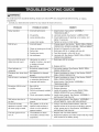
[_WARNINGI
To avoidinjury
from accidental
starting,
alwaysturnswitchOFF and unplugthetoolbeforemoving,or making
adjustments.
• ConsultyourSears ServiceCenterifforany reasonthemotor willnotrun.
PROBLEM
Noisy operation
Drill bit burn.
POSSIBLE CAUSES
REMEDY
1, Incorrect belt tension,
1. Adjust tension. See section "ASSEMBLYTENSIONING BELT"
2. Dry spindle.
3. Loose spindle pulley.
2. Lubricate spindle. See Section "LUBRICATION".
3. Check tightenness of retaining nut on pulley, and
4. Loose motor pulley.
tighten if necessary.
4. Tighten set screw in motor pulley.
1. Incorrect speed.
1. Change speed. See Section " BASIC DRILL PRESS
OPERATION-SPEEDS
AND BELT REPLACEMENT"
2. Chips not coming out of hole. 2.
3. Dull drill bit.
3.
4.
4. Feeding too slowly.
5.
5. Not lubricated.
Run out of drill bit pointdrilled hole not round.
,
,
1. Resharpen drill bit correctly.
lengths of cutting utes and/
or angles not equal.
Bent drill bit.
2. Replace drill bit.
1. No backup material under
workpiece.
Workpiece torn loose from 1. Not supported or clamped
hand.
properly.
1.
Drill bit binds in workpiece.
Workpiece pinching drill bit,
or excessive feed presure.
2. Improper belt tension.
1. Coil spring has improper
tension.
1. Dirt, grease, or oil on the
Chuck will not stay
attached to spindle. It falls
tapered inside surface of
off when trying to install.
chuck or on the spindle's
Quill returns too slow or
too fast.
The laser guide will not
turn on.
1. Use backup material. See Section "BASIC DRILL
PRESS OPERATION".
1. Support workpiece or clamp it. See Section "BASIC
DRILL PRESS OPERATION".
1. Support workpiece or clamp it. See Section "BASIC
DRILL PRESS OPERATION".
2. Adjust tension. See Section" ASSEMBLY TENSIONING BELT".
1. Bent drill bit.
2. Worn bearings.
3. Drill bit not properly installed
in chuck,
4. Chuck not properly installed.
.
Resharpen drill bit or replace with new bit.
Feed fast enough - allow drill to cut.
Lubricate drill. See Section "BASIC DRILL PRESS
OPERATION-FEEDING"
Hand grain in wood or
Wood splinters on
underside.
Excessive drill bit runout
or wobble.
Retract drill frequently to clear chips.
1. Use a straight drill bit.
2. Replace bearings.
3. Install drill properly. See Section "BASIC DRILL
PRESS OPERATION" and "ASSEMBLY".
4. Install chuck properly. See Section "ASSEMBLYINSTALLING THE CHUCK".
1. Adjust spring tension. See Section "ASSEMBLY
ADJUSTMENTS -QUILL RETURN SPRING".
-
1. Using a non-alcohol based cleaner, clean the
tapered surface of the chuck and spindle to remove
all dirt, grease and oil. See Section "ASSEMBLYINSTALLING THE CHUCK".
tapered surface.
The batteries are dead.
1. Replace with new AAA batteries.
2. The battery contacts need
adjustment.
2. Reload the batteries and make certain that they make
solid contact to the battery spring.
24
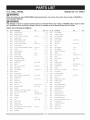
10 in. DRILL PRESS
MODEL NO. 137.219001
WAR.I.G
J
When servicing use only CRAFTSMAN
cause product damage.
replacement
parts. Use of any other parts many create a HAZARD or
WAR.I.G
J
Any attempt to repair or replace electrical parts on this Drill Press may create a HAZARD unless repair is done
by a qualified service technician. Repair service is available at your nearest Sears Service Center.
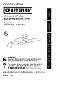
PARTS LiST FOR SAW SCHEMATIC
QTY
No.
I.D. No.
Des€rip}ion
No.
I.D. No.
Descrip}ion
1
X4NH
PULLEY SET NUT
58
X4LU
AAA BATTERY
2
2
X4NG
SPINDLE PULLEY
69
X4LH
WARNING
1
9
X4N9
CR. RE. COUNT HD. SCREW
4
72
X4LE
CAUTION
10
X4N8
CLEAR PANEL
2
73
X4LD
LASER STICKER
11
X4N7
SPEED DIAGRAM
74
X4LC
FLAT WASHER
12
X4N6
PULLEY COVER ASS'Y
#06
76
X4LA
CHUCK KEY
13
X4N5
CR. RE. PAN HD. SCREW
M5"0.8-12
6
77
X4L9
HEX. NUT
14
X4N4
CLAMP-CORD
3
82
X4L4
ROD
15
X4N3
CR. RE. ROUND
5
83
X4L3
HEX. WRENCH
3 mm
1
16
X4N2
V-BELT
84
X4L2
HEX. WRENCH
4 mm
1
17
X4N 1
SPEED DIAGRAM
85
X4L1
TABLE LOCK HANDLE
89
X4KX
TABLE
#AW
1
90
X4KW
HEX. HD. BOLT
1/2"12UNC-7/8
1
93
X4KT
RACK
95
X4KR
HEX. HD. BOLT
M8"1.25-25
3
97
X4KP
BASE
#06
98
X4KN
FASTNESS KNOB
99
X4KM
FLAT WASHER
3/8"1 5/32-7/64
4
104
OKQ4
BUTTERFLYNUT
M8"1.25
2
105
X4KF
SCALE
108
OKD5
CR. RE. PAN HD. SCREW
M4"0.7-6
2
18
X4N0
Size
M4"0.7-8
LABEL
WASHER HD. SCREW
M6"1.0-12
K-30
STRAIN RELIEF
cp20
2
cp2.3-5
4
Size
LABEL
LABEL
QTY
1
2
1/4"5/8-1/16
2
1
M6"1.0 T=5
1
1
1
19
X4MZ
DRIVE SCREW
20
X4MY
WARNING
21
X4MX
TRADE-MARK
22
X4MW
CHUCK KEY HOLDER
23
X4MV
SHIFTER BOLT
24
X4MU
HEAD
25
X4MT
HEX. SOC. SETSCREW
26
X4MS
FEED SHAFT
27
X4MR
FLAT WASHER
28
X4MQ
SPRING
10
OLZ5
CAPACITOR
29
X4MP
MOTOR ROD
11
2ENN
CAPACITOR
30
X4MN
HEX. HD. SCREW AND WASHER
12
X4K7
FLAT WASHER
32
X4ML
MOTOR BASE
13
X4K6
LABEL
1
33
X4MK
LOCK NUT
14
X4K5
OPERATOR'S MANUAL
1
34
X4MJ
SPRING PIN
15
X4K4
POWER CABLE
1
35
X4MH
CORD-CLAMP
16
X4NK
SWITCH KEY
1
36
X4MG
HEX. NUT
M8"t.25
A
X4K3
DRIVING SLEEVE ASS'Y
1
37
X4MF
QUILL SETSCREW
M8"1.25-14
B
X4K2
MOTOR PULLEY ASS'Y
1
38
X4ME
STICKER
C
X4K1
HANDLE BAR ASS'Y
3
39
X4MD
EXTERNAL TOOTH LOCK WASHER
cp5
2
D
X4K0
MOTOR ASS'Y
1
40
X4MC
CR. RE. PAN HD. SCREW
M5"0.8-8
2
E
X4JZ
SPRING CAP ASS'Y
1
43
X4M9
HEX. NUT
3/8*24UNF
2
F
X4JY
RACK RING ASS'Y
1
44
X4M8
POINTER
G
X4JX
CRANK HANDLE ASS'Y
1
45
X4M7
SET BOLT
M10"1.5
H
X4JW
TABLE BRACKET ASS'Y
1
46
X4M6
NUT
M10"1.5-2B
J
X4JU
FENCE HARDWARE
1
47
X4M5
DEPTH SCALE
K
X4JT
COLUMN
48
X4M4
SWITCH BOX
L
X4JS
LOCATION
49
X4M3
SWITCH COVER
M
X4JR
LASER ASS'Y
1
50
X4M2
CR. RE. TRUSS HD. TAPPING SCREW
N
X4JQ
CHUCK & KEY
1
51
X4M1
ROCKER SWITCH
Q
X4JN
QUILL ASS'Y
1
52
X4MO
TERMINAL
LABEL
LABEL
M8"1.25-20
M8"1.25-8
3
1/4"3/4-3/16
4
M8"1.25-25
2
M8"1.25 T=8
2
M4"16-12
T=6.5
T=8
1
1
2
1
1
BOX
1
cpS*l 6-2.5
BAG ASS'Y
ASS'Y
PIN ASS'Y
4
1
1
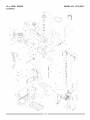
10 in. DRILL PRESS
MODEL
NO. 137.219001
SCHEMATIC
114
16
D
[
[
...... C
[
//
[
\
29
\\'26
49
50
51
116
//83
84
H
85
58
,\
?
/./
Congratulations on making a smart purchase. Your new Craftsman ® product is designed and manufactured for years
of dependable operation. But like all products, it may require repair
from time to time. That's when having a Repair Protection Agreement can save you money and aggravation.
Here's
what
the Repair
Protection
Agreement*
includes:
[] Expert service by our 10,000 professional repair specialists
[] Unlimited service and no charge for parts and labor on all covered repairs
[] Product replacement up to $1500 if your covered product can't be fixed
[] Discount of 10% from regular price of service and related installed parts not covered by the agreement; also,
10% off regular price of preventive maintenance check
[] Fast help by phone - we call it Rapid Resolution - phone support from a Sears representative.
"talking owner's manual."
Think of us as a
Once you purchase the Repair Protection Agreement, a simple phone call is all that it takes for you to schedule
service. You can call anytime day or night, or schedule a service appointment online.
The Repair Protection Agreement is a risk-free purchase. If you cancel for any reason during the product warranty
period, we will provide a full refund. Or, a prorated refund anytime after the product warranty period expires.
Purchase your Repair Protection Agreement today!
Some limitations
1=800=827-6655.
and exclusions
apply. For prices and additional
information
in the U.S.A. call
*Coverage in Canada varies on some items. For full details call Sears Canada at 1=800=361=6665.
Sears Installation
Service
For Sears professional installation of home appliances, garage door openers, water heaters, and other major home
items, in the U.S.A. or Canada call 1-800-4-MY-HOME ®.
Your Home
For expert troubleshooting
and home solutions advice:
www.managemyhome.com
For repair - in your home - of all major brand appliances,
lawn and garden equipment, or heating and cooling systems,
no matter who made it, no matter who sold it!
For the replacement parts, accessories and
owner's manuals that you need to do-it-yourself.
For Sears professional installation of home appliances
and items like garage door openers and water heaters.
1-800-4-MY-HOME
Call anytime,
®
(1-800-469-4663)
day or night (U.S.A. and Canada)
www.sears.com
www.sears.ca
Our Home
For repair of carry-in items like vacuums, lawn equipment,
and electronics, call anytime for the location of your nearest
Sears Parts & Repair Service
1-800-488-1222
(U.S.A.)
1-800-469-4663
To purchase a protection agreement
on a product serviced by Sears:
(U.S.A.)
Para pedir servicio de reparaci6n
a domicilio, y para ordenar piezas:
1-888-SU-HOGAR
1-800-361-6665
(Canada)
Au Canada pour service
en fran£ais:
1-800-LE-FOYER
®
Trademark
/ TMTrademark
/ SMService
M°
(1-800-533-6937)
www.sears.ca
(1-888-784-6427)
® Registered
(Canada)
www.sears.ca
www.sears.com
1-800-827-6655
Center
Mark of Sears Brands,
® Marca Registrada / TM Marca de Fabrica / SM Marca de Servicio
MC Marque de commerce / MD Marque depos6e de Sears Brands,
LLC
de Sears Brands,
LLC
LLC
© Sears
Brands,
LLC