1
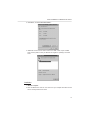
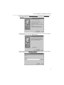
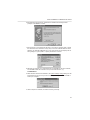
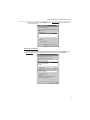
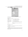
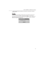
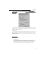
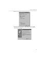
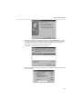
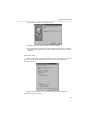
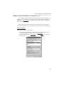
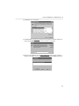
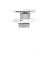
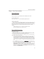
User’s Manual
Fast Ethernet CardBus
(MPC-200)
acsense
R
Table of Contents
Chapter 1 Introduction . . . . . . . . . . . . . . . . . . . . . . . . . . . . . . . . . . . .1
Features . . . . . . . . . . . . . . . . . . . . . . . . . . . . . . . . . . . . . . . . . . . . . .1
Network Interface . . . . . . . . . . . . . . . . . . . . . . . . . . . . . . . . . . . . . . .1
Driver support . . . . . . . . . . . . . . . . . . . . . . . . . . . . . . . . . . . . . . . . . .1
Physical characteristics . . . . . . . . . . . . . . . . . . . . . . . . . . . . . . . . . . .2
Quick Installation . . . . . . . . . . . . . . . . . . . . . . . . . . . . . . . . . . . . . . . .2
Installing the Fast Ethernet CardBus Card . . . . . . . . . . . . . . . . . . . . .2
Setup for Windows 95 . . . . . . . . . . . . . . . . . . . . . . . . . . . . . . . . . . . .2
Setup for Windows 98 . . . . . . . . . . . . . . . . . . . . . . . . . . . . . . . . . . . .3
Chapter 2 Getting Started . . . . . . . . . . . . . . . . . . . . . . . . . . . . . . . . . .5
Installing the Fast Ethernet CardBus Card . . . . . . . . . . . . . . . . . . . . .5
LED Indicators . . . . . . . . . . . . . . . . . . . . . . . . . . . . . . . . . . . . . . . . . .5
README.TXT . . . . . . . . . . . . . . . . . . . . . . . . . . . . . . . . . . . . . . . . . .6
Chapter 3 Driver Installation for Windows 95 OSR 2 . . . . . . . . . . . . .7
System Requirements . . . . . . . . . . . . . . . . . . . . . . . . . . . . . . . . . . . .7
Check Version of Windows 95 . . . . . . . . . . . . . . . . . . . . . . . . . . . . . .7
Check CardBus Driver's Version . . . . . . . . . . . . . . . . . . . . . . . . . . . .7
Installation . . . . . . . . . . . . . . . . . . . . . . . . . . . . . . . . . . . . . . . . . . . . .8
Advanced Properties . . . . . . . . . . . . . . . . . . . . . . . . . . . . . . . . . . . . .11
Connection Type . . . . . . . . . . . . . . . . . . . . . . . . . . . . . . . . . . . . . . . .12
Receive Buffers . . . . . . . . . . . . . . . . . . . . . . . . . . . . . . . . . . . . . . . . .12
Snooze Mode . . . . . . . . . . . . . . . . . . . . . . . . . . . . . . . . . . . . . . . . . .12
Hot Swap . . . . . . . . . . . . . . . . . . . . . . . . . . . . . . . . . . . . . . . . . . . . .13
Chapter 4 Driver Installation for Windows 98 . . . . . . . . . . . . . . . . . . .15
Installation . . . . . . . . . . . . . . . . . . . . . . . . . . . . . . . . . . . . . . . . . . . . .15
Upgrading Steps . . . . . . . . . . . . . . . . . . . . . . . . . . . . . . . . . . . . . . . .16
i
Advanced Properties
. . . . . . . . . . . . . . . . . . . . . . . . . . . . . . . . . . . .20
Chapter 5 Driver Installation for Windows NT 3.5.1 . . . . . . . . . . . . . .21
Driver Installation . . . . . . . . . . . . . . . . . . . . . . . . . . . . . . . . . . . . . . . .21
NDIS 3 Driver Parameters for Windows NT 3.51 . . . . . . . . . . . . . . . .22
Chapter 6 Driver Installation for Windows NT 4.0 . . . . . . . . . . . . . . . .23
Driver Installation . . . . . . . . . . . . . . . . . . . . . . . . . . . . . . . . . . . . . . . .23
Chapter 7 Client Driver Installation . . . . . . . . . . . . . . . . . . . . . . . . . . .27
System Requirements . . . . . . . . . . . . . . . . . . . . . . . . . . . . . . . . . . . .27
Driver Installation Brief Overview . . . . . . . . . . . . . . . . . . . . . . . . . . . .27
Dos ODI Client Driver Installation NetWare 3.x/4.x Client . . . . . . . . . .28
NDIS Driver For Windows for Workgroups 3.11 . . . . . . . . . . . . . . . . .30
NDIS Driver For LAN Manager . . . . . . . . . . . . . . . . . . . . . . . . . . . . . .30
Appendix A Troubleshooting for Windows Environment and PCI
CardBus bridge Utility . . . . . . . . . . . . . . . . . . . . . . . . . . .33
Windows 95 OSR 2 . . . . . . . . . . . . . . . . . . . . . . . . . . . . . . . . . . . . . .35
Windows NT 4.0 . . . . . . . . . . . . . . . . . . . . . . . . . . . . . . . . . . . . . . . .34
PCI CardBus Bridge Utilities . . . . . . . . . . . . . . . . . . . . . . . . . . . . . . .34
Appendix B PCI to CardBus Bridge Utilities . . . . . . . . . . . . . . . . . . .37
Introduction . . . . . . . . . . . . . . . . . . . . . . . . . . . . . . . . . . . . . . . . . . . .37
Utilities Description . . . . . . . . . . . . . . . . . . . . . . . . . . . . . . . . . . . . . .37
Typical Usage . . . . . . . . . . . . . . . . . . . . . . . . . . . . . . . . . . . . . . . . . .40
PCI to CardBus Bridges Supported . . . . . . . . . . . . . . . . . . . . . . . . . .41
Appendix C Specifications . . . . . . . . . . . . . . . . . . . . . . . . . . . . . . . . . .43
Appendix D Pin Assignment . . . . . . . . . . . . . . . . . . . . . . . . . . . . . . . .45
RJ-45 Connector . . . . . . . . . . . . . . . . . . . . . . . . . . . . . . . . . . . . . . . .45
ii
Chapter 1 Introduction
Introduction
Chapter 1 Introduction
This manual describes how to operate the Fast Ethernet CardBus Card. The Fast
Ethernet CardBus Card is a Credit-card sized Ethernet Card which works with any computer, notebook, sub-notebook or Card Reader that supports CardBus slots.
CardBus is a function and performance extension of the PC Card (PCMCIA) standards. The CardBus interface is a 32-bit wide and Bus-mastering allowable device. It
enhanced the overall system throughput.
This Fast Ethernet CardBus Card could be connected to either 100Mbps Fast Ethernet
or 10Mbps Ethernet network.
¥ For operating in a 100Mbps (100BASE-TX) Fast Ethernet network, a Category 5
unshielded twisted pair (UTP) cable or Category 1 shielded twisted pair (STP) cable
should be used.
¥ For operating in a 10Mbps (10BASE-T) Ethernet network, a Category 3,4, or 5
(UTP) cable or Category 1 shielded twisted pair (STP) cable could be used.
Features
¥ CardBus form factor for CardBus equipped portable PCs
¥ IEEE 802.3 for 10BASE-T and IEEE 802.3u for 100BASE-TX compliant
¥ Automatically negotiates 10Mbps or 100Mbps connection speed, depending on
speed of the network
¥ Provides full-duplex to enhance throughput
¥ Offer high performance 100Mbps networking via 32-bit, PCI CardBus slot
¥ Complies to PC Card 1995 CardBus standards
¥ Switch less design and software configurable card setting
¥ 68-pin connector for attachment to PC's CardBus slot, and 15-pin flat connector to
media coupler
¥ 3.3V low power consumption
¥ LEDs monitoring indicators
Network Interface
¥ RJ-45 to connect with 10BASE-T or 100BASE-TX Hub or Switch
Driver Support
¥ NDIS2 for Novell NetWare DOS ODI
¥ NDIS2 for Windows for Workgroups 3.11
¥ NDIS2 for Microsoft LAN Manager
¥ NDIS3 for Microsoft Windows NT 3.51
1
Introduction
¥ NDIS4 for Microsoft Windows 95 OSR2, and Windows 98
¥ NDIS4 for Microsoft Windows NT 4.0
Physical Characteristics
¥ Standard Conformance: IEEE 802.3 for 10BASE-T
IEEE 802.3u for 100BASE-TX
¥ Host Interface: PC Card 95 CardBus Standard
¥ Ethernet Data Speed: 10Mbps and 100Mbps (Auto-Negotiation)
¥ Bus Width: 32 bits
¥ Power: 3.3 V
¥ Temperature: 0ûC~60ûC/ 32ûF~140ûF (Std. Operating)
¥ Humidity: 10% to 90%
¥ Distance: 100m from Hub to Node
¥ Dimensions: 86mm x 54mm x 5 mm
Quick Installation
Installing the Fast Ethernet CardBus Card
You will be installing the Fast Ethernet CardBus Card in your computer. If you are
having trouble locating the slot, refer to your computer's user's manual or consult the
manufacture of your computer.
Gently slide the PC Card into the PC Card slot. Make sure the Card is firmly seated in
the socket and you are ready to setup and install the network drivers.
For a connection to a Fast Ethernet network, use a Category 5 unshielded twisted pair
(UTP) or Category 1 shielded twisted pair (STP) cable with RJ-45 connector to connect
with 100Mbps port of a hub or switch.
For a connection to a 10BASE-T Ethernet network, use a Category 3,4 or 5 UTP or
STP 1 cable with RJ-45 connector to connect with 10Mbps port of a hub or switch.
Setup for Windows 95
Windows 95 OSR2 (OEM Service Release #2) and later versions contain all drivers
necessary for accessing your Fast Ethernet CardBus Card. Before the installation, please
follow these steps to check the version of Windows 95 and CardBus driver.
1. Click the Start button and select Settings .
2. Click Control Panel , and double-click the System icon.
3. Select General . The version of Windows 95 will be displayed under the
system field. Remember, only 4.00.950b and later versions (4.00.950c or 4.00.951)
fully support CardBus.
2
Introduction
4. Select Device Manager, click PCMCIA socket , then select one CardBus controller
and click Properties .
5. Click Driver, and select Driver File Details ... .
6. CBSS.VXD will be found and its version must be 4.10.1387 or later.
If your CardBus driver is older, please contact your Windows 95 supplier for updating
to the latest version.
After getting the correct version, just follow these steps to get up and running:
1. Start the computer.
2. Insert the Fast Ethernet CardBus Card into a PC Card slot in your computer. Make
sure the card is securely inserted into the socket. Windows will display the Update
Device Driver Wizard dialog box. Click next, select Other Locations button and
key in A:/ in the location, where the device information file (.inf file) can be found.
Insert Ethernet Driver Diskette into driver A and click OK. Windows will find the Fast
Ethernet CardBus Card.
3. Click Finish to start installing the necessary drivers.
4. Follow the instructions of Windows 95 to install the Ethernet Driver Diskette in
drive A and Windows 95 CD-ROM in CD-ROM driver.
5. After installing the desired drivers, the Ethernet adapter will be enabled, and the
LED indicator will be turned on if network is available.
Setup for Windows 98
In the case of Windows 98, you do not need to check the version of your Operating
System. Windows 98 supports CardBus drivers for many kinds of CardBus controllers and
drivers for the Digital Semiconductor LAN Controller 2114x family. Taking the advantages
of these new characteristics and the Plug & Play feature, you can simply hot plug your
Fast Ethernet CardBus Card into the CardBus socket of your notebook and follow the
instructions showed on the screen to finish the installation process. As the manufacturer of
this Fast Ethernet CardBus Card, we do know some notebook computers have problems
to drive this card by using the driver that come with Windows 98. But mostly they could be
solved by upgrading this card driver to one supplied in you driver diskette.
Upgrading steps:
1. Start the computer.
2. Insert the Fast Ethernet CardBus Card into a PC Card slot in your computer. Make
sure the card is securely inserted into the socket. Double-click the System icon
from the Control Panel. Select Device Manager, then double-click PCI Fast
Ethernet DEC 21143 BASEd Adapter from Network adapters and select Update
Driver from PCI Fast Ethernet DEC 21143 Based Adapter Properties.
3. Windows will display the Update Device Driver Wizard dialog box. Click next. Then
select Display a list of all the drivers in a specific location, so you can select
the drive you want. Click next. Then, Windows will display the Select Device dialog
box. Click Have Disk and then key in A:/ for the location of where the device information file (.inf file) can be found. Insert the Fast Ethernet CardBus Card Driver
3
Introduction
Diskette into drive A and click OK. Windows will find the Fast Ethernet CardBus
Card .
4. Click Next to start installing the necessary drivers.
5. Type A: / for the location of where the files are stored in the Copying Files dialog
box and click OK.
6. Click Finish to complete the installation process.
7. Follow the instructions of Windows 98 to restart your computer.
8. After installing the desired drivers and restarting on Windows 98, the Ethernet
adapter will be enabled, and the LED indicators will be turned on if network is available
4
Hardware Installation
Chapter 2 Getting Started
Installing the Fast Ethernet CardBus Card
You will be installing the Fast Ethernet CardBus Card in CardBus slot of your computer. If you have trouble locating the slot, please refer to your computer's userÕs manual or
consult the manufacture of your computer.
Follow the procedure below to install the Fast Ethernet CardBus Card.
1. Turn off the host computer.
2. With the card's 68 pin connector facing the PCMCIA CardBus slot, gently slide the
PC Card into the CardBus slot. Make sure the card is firmly seated in the socket
3. Plug the Ethernet adapter cable to the 15-pin connector on the Fast Ethernet
CardBus Card as in the following figure below.
4. Connect your Ethernet adapter cable to the network using a RJ-45 cable.
5. Power on your notebook computer.
6. Now you are ready to install your communication software as described in the
following chapters.
LED Indicators
¥ 100 LED: This LED is used to indicate the Ethernet speed: The green light
indicates a connection with a 100BASE-TX Fast Ethernet network.
¥ Link/Act LED: This LED is used to indicate the network activity. It is blinking when
5
Hardware Installation
the PC Card is transmitting or receiving packets from network. It is
also lit when a Link to the network is acquire.
README.TXT
There is one file named Readme.txt on driver diskette which provides the information
about this Driver Diskette's contents and installation guide. This file is located in the root
directory of the diskette.
6
Driver Installation for Windows 95 OSR 2
Chapter 3 Driver Installation for Windows 95 OSR 2
System Requirements
Windows 95 may come with most of the drivers necessary for accessing your Ethernet
card, but only OSR2 (OEM Service Release #2) and later versions fully support CardBus
adapters. Before the installation, please follow the steps below to check the version of
Windows 95 and CardBus drivers.
Check Version of Windows 95
1. Click the Start button and select Settings.
2. Click Control Panel, and double-click the System icon.
3. Select General. The version will be displayed under the system field. Remember,
only 4.00.950b and later versions (4.00.95c or 4.00.951) fully support CardBus.
Check CardBus Driver's Version
1. Select Device Manger, then click PCMCIA socket, then select one CardBus
controller, and click Properties. The following diagram is an example for a TI PCI1130 CardBus controller.
7
Driver Installation for Windows 95 OSR 2
2. Click Driver, and select Driver File Details....
3. CBSS.VXD is found and its version must be 4.10.1387 or later, If your CardBus
driver is older, please contact your Windows 95 supplier for updating to the latest
driver.
Installation
1. Start the computer.
2. Insert the Ethernet PC card into a PC Card slot in your computer and make sure the
card is securely seated in the socket
8
Driver Installation for Windows 95 OSR 2
3. Windows will prompt with New Hardware Found and display the Update Device
Driver Wizard dialog box. Insert driver diskette into Driver A and click Next.
4. Windows will try to find the driver for this card. If it displays Windows was unable to
locate for this device , just select Other Location.
5. When Windows display Select Other Location dialog box, input the driver's location
A:/ and click OK when the driver diskette is inserted in drive A.
9
Driver Installation for Windows 95 OSR 2
6. After Windows finds the driver, Fast Ethernet CardBus Card message will be
prompted. Click Finish to confirm.
7. After the driver is found, Windows will begin to copy all the necessary files to install
the network functions. Windows 95 may ask you to insert a labeled Ethernet Driver
Diskette , just click OK. If Windows try to copy mpc-200.inf file and displays the following dialog box, just input A:/ to specify the location of this file.
8. Windows may request you to Insert Windows 95 CD-ROM into the driver selected,
and click OK. Follow this instruction and input CD-ROM location, e.g.
D:\OSR2\SETUP.
9. When Windows finishes the installation, the System Settings Change dialog box will
be prompted and ask you Do you want to restart your computer now . Click Yes to
restart your computer.
10. After computer is restarted, the network function gets ready.
10
Driver Installation for Windows 95 OSR 2
11. You can use the PC Card (PCMCIA) icon in Control Panel to check whether the
card is ready or not.
Advanced Properties
To change the properties of your Fast Ethernet CardBus Card, select Network from
the Control Panel, then select Fast Ethernet CardBus Card and click Properties.
11
Driver Installation for Windows 95 OSR 2
Next, click the Advanced tab . You will then see the following property sheet: The configurable properties are given in the Property list. Click the property you want to configure
and choose your desired setting from the Value drop-down menu.
The following sections describe the meaning of each property and its default value.
Connection Type
Permissible connection types are:
100BASE-TX
to connect 100BASE-TX Ethernet Hubs
100BASE-TX Full Duplex
to connect 100BASE-TX Full Duplex Hubs
10BASE-T (Twisted Pair)
to connect 10BASE-T Ethernet Hubs
10BASE-T Full Duplex
to connect 10BASE-T Full Duplex Hubs
10BASE-T No_Link_Test
to connect 10BASE-T Ethernet Hubs without Link Integrity
Test
AutoSense
Sense dynamically the media ports to determine the connection type
The default setting is AutoSense.
Receive Buffers
The number of buffers allocated by the driver in the receive ring. The valid values are
8, 16, 32, 48, and 64. The default setting is 16.
Snooze Mode
If Snooze Mode is enabled, the card will enter snooze mode and most of its clocks will
be disconnected to save power. The card will temporarily exit from Snooze Mode to normal
operation mode upon sensing network activity, start of a transmission, or when it is being
accessed by the host.
12
Driver Installation for Windows 95 OSR 2
When the Snooze Mode is disabled, the card will be in normal mode. The default
setting is Disabled.
Hot Swap
This Fast Ethernet CardBus Card supports the hot-swap function. But, before you
remove the PC card from CardBus slot, please click PCMCIA icon on task bar or in
Control Panel illustrated as previous diagram and select STOP to force this adapter to be
inactive. When You may safely remove this device. message is prompted, click OK and
remove your Fast Ethernet CardBus Card.
13
Setup for Windows 98
Chapter 4 Setup for Windows 98
Installation
Hot Plug-in Installation
Windows 98 supports CardBus drivers for many kinds of CardBus controllers and
drivers for Digital Semiconductor LAN Controller 2114x family. Taking the advantages of
these new characteristics and the Plug & Play feature, you simply hot plug your Fast
Ethernet CardBus Card into the CardBus socket of your notebook computer and follow the
instructions shown on the screen to finish the installation process.
Check Card Status
Please check Device Manager in System Properties to make sure the Fast Ethernet
CardBus Card is working properly.
15
Chapter 5 Driver Installation for Windows 98
Setup for
Double-click Macsense Fast Ethernet CardBus Card in the Device Manager of
System Properties. Then Windows will display the Macsense Fast Ethernet CardBus Card
Properties dialog box.
Check information in Device status. If the information shows This device is not working
properly, please follow the steps described in the next section to upgrade your Macsense
Fast Ethernet CardBus Card drivers.
Upgrade Drivers
As the manufacturer of this Macsense Fast Ethernet CardBus Card, we do know some
notebook computers have problems to drive this card by using the driver that come with
Windows 98. But mostly they could be solved by upgrading this card driver to one supplied
in you driver diskette.
Upgrading Steps
Upgrading steps as following:
1. Start the computer.
2. Insert the Macsense Fast Ethernet CardBus Card into a PC Card slot in your computer. Make sure the card is securely inserted into the socket. Double-click the
System icon from the Control Panel . Select Device Manager , then double-click
Macsense Fast Ethernet CardBus Card from Network adapters and select
16
Setup for Windows 98
Update Driver from Macsense Fast Ethernet CardBus Card .
3. Windows will display the Update Device Driver Wizard dialog box. Click Next,
select Display a list of all the drivers in a specific location, so you can select the
drive you want. and click Next.
17
Setup for Windows 98
4. Windows will display the Select Device dialog box. Click Have Disk and then key in
A:/ in the location, where the device information file (.INF file) can be found. Insert
the Macsense Fast Ethernet CardBus Card Driver Diskette into drive A and click
OK, Windows will find the Fast Ethernet CardBus Card .
5. Click Next to start installing the necessary drivers.
6. Type A:/ in the location, where the files will be copied from the Copying Files dialog
box and click OK.
18
Setup for Windows 98
7. Click Finish to complete the installation process.
8. Follow the instructions of Windows 98 to restart your computer.
9. After installing the desired drivers and restart Windows 98, the Macsense FastEther
CardBus Card will be enabled, and the LED indicators will be turned on if network is
connected.
Check Card Status
Double-click Macsense Fast Ethernet CardBus Card in the Device Manager of System
Properties. Then Windows will display the Macsense Fast Ethernet CardBus Card
Properties dialog box.
Check information in Device status to make sure your Macsense Fast Ethernet
CardBus Card is working properly.
19
Setup for Windows 98
Advanced Properties
To change the properties of your Fast Ethernet CardBus Card, please refer to the last
chapter Advanced Properties.
20
Driver Installation for Windows NT 3.51
Chapter 5 Driver Installation For Windows NT 3.51
Driver installation
1. In the Main group of NT, select the Control Panel icon.
2. In the Control Panel window, select the Network icon.
3. In the Network Settings dialog box, select the Add Adapter button. The Add
Network Adapter dialog box appears.
4. In the list of network cards, select <other> Requires disk from manufacturer, and
then press <Enter> button.
5. Insert this driver disk in drive A. Enter drive and pathname A:/ and click the OK
button.
6. In the Select OEM Option dialog box, the following adapter name is displayed.
Select this adapter and click the OK button to install it.
Macsense Fast Ethernet CardBus Card
7. The Macsense Fast Ethernet CardBus Card Setup dialog box appears. You should
specify the correct values of these parameters for MPC-200 to work. Check the section on NDIS 3 Driver Parameters for Windows NT 3.51 for more information about
how to configure the parameters.
8. The system copies MCBNDIS3.SYS from the \WINNT directory on the driver disk to
C:\WINNT\SYSTEM32\DRIVERS\MCBNDIS3.SYS, and the OEMSETNT.INF from
\WINNT351 to C:\WINNT\SYSTEM32 but gives it another name (e.g.
OEMNAD??.INF). If you remove the MPC-200 driver and would like to re-install it
later, you do not need the driver disk again. In the above, we assumed C:\WINNT is
the directory where the Windows NT system files are installed.
9. To complete network installation, remember binding the adapter to transport drivers
by selecting the Bindings button under the Network Setting dialog box.
10. Insert the Fast Ethernet CardBus Card in one of the CardBus sockets.
Attach the coupler to the back of the card, and connect a cable from the RJ-45 connector on the back of the coupler to a hub or switch.
You can now shutdown and restart the computer. Please note during Windows NT
initialization, MPC-200 must be properly connected to a hub or switch; otherwise the card
and driver would not communicate correctly.
Note: If you are connected to a 100Mbps network, be sure to use UTP-5 or STP-1 cable.
21
Chapter 6 Driver INstallation for Windows NT 4.0
Driver
NDIS 3 Driver Parameters for Windows NT 3.51
Connection_Type:
Specify the attached medium type. Default is AutoSense.
I/O_Port:
Specify the starting address of I/O port range. The default
value is D000.
Memory_Base_Address:
Specify the starting address of the Shared Memory range.
The default value is D0000.
Interrupt_Number:
Socket_Number:
Specify the IRQ number. The default value is IRQ 11.
Specify the socket number in which an mpc-200 is inserted.
The default value is Auto detect.
Interrupt_Style:
Specify the CardBus bridge interrupt routing strategy.
Default is PCI-IRQ-Routed .
Interrupt_Routing:
Specify which interrupt pin is used while the CardBus
bridge is using PCI-IRQ-Routed . Default is INT A.
Store_And_Forward:
Setting this parameter causes the NIC to disable the transmit data pipeline operation. Default is ON.
It is extremely important to assign correct values for the Interrupt_Number (IRQ value)
and Interrupt_Style parameters. If the system uses the PCI-IRQ-Routed interrupt style, it
is also important to assign the correct PCI Interrupt_Routing value (i.e. INT A or INT B.)
If in doubt about the values to assign to these parameters, you are advised to execute
the STARTER.EXE enabling program in a native MS-DOS system first. STARTER.EXE
displays the IRQ value used, as well as the system's interrupt style. For the Windows NT
driver, you should assign the same values to the above parameters as those displayed by
STARTER.
22
Driver Installation For Windows NT 4.0
Chapter 6 Driver Installation For Windows NT 4.0
The installation procedure assumes the network component has been installed on your
computer. To check whether the network component has been installed, double click the
Network icon in Control Panel. If not installed, refer to the Windows NT 4.0 installation
guide to install the component.
While installing the network component, Windows NT 4.0 will ask you to install the
driver of network adapter. The driver installation procedure is similar to the following one.
Driver Installation
Follow the steps below to install the driver.
1. Insert the Macsense Fast Ethernet CardBus Card into an open CardBus slot on
your notebook computer. Login to NT 4.0 as the administrator.
2. Double click Network icon in Control Panel, and select Adapters tab, the window
below will show.
23
Driver Installation For Windows NT 4.0
3. Click Add to add a new adapter..
4. Click Have Disk. The Insert Disk window, shown in Figure is displayed. Specify the
search path, A:\WINNT40, then insert driver diskette, and click OK.
5. After finding the installation file, the Select OEM Option window shown in Figure is
displayed. Click OK to choose the Macsense Fast Ethernet CardBus Card option.
24
Driver Installation For Windows NT 4.0
6. In the Configuration of Macsense Fast Ethernet CardBus Card window select the
desired connection type from Connection Type pull down menu. Leave the
CardBus Enable setting as Enable. After selecting desired configuration, click OK.
7. Click Close to close the Network window, and let Windows NT 4.0 bind the adapter
with the network component.
8. Eventually, Windows NT 4.0 will prompt you to restart the computer, click Yes to
finish installation.
25
Client Driver Installation
Chapter 7 Client Driver Installation
System Requirements
Hardware Requirements
Notebook equipped with Type II CardBus slot and CardBus Socket controller.
Firmware Requirements
Fully complies with Rev. 2.1 or above PCI BIOS supplied with the PC.
Software Requirements
Due to the newness of the CardBus specification, most Card and Socket Services software still do not currently support CardBus devices. The Card & Socket Service drivers
should comply with PC Card Standard, February 1995 or later version. For your reference,
the following DOS versions of the Card and Socket Services are known to support
CardBus:
¥ AMICard Manager Pro Ver 2.1.2 (supports CL-PD6832, TI113X)
¥ Phoenix Card Manager Ver 2.0 (supports TI113X)
Driver Installation Brief Overview
The INSTALL Program
Before your computer system can recognize your Macsense Fast Ethernet CardBus
Card, the driver programs must first be installed to enable the card.
This section gives a brief overview of the installation process.( For a clearer step-bystep procedure, refer to the next section.)
1. If the Card and Socket Services software is included as part of your computer, it is
recommended that you use this software when installing your Macsense Fast
Ethernet CardBus Card. A system with Card and Socket Services installed allows
the PCMCIA card to be automatically configured. While the system is on, available
system resources and insertion or removal of the card will automatically be detected.
2. Run the INSTALL batch file locate on your Installation Disk (like InstNwCl.bat etc.).
3. IF you have not installed Card and Socket Services or your card does not work with
current version of Card and Socket Services, use the direct enabler,
STARTER.EXE, to enable the CardBus controller. The direct enabler communicates
directly with the CardBus controller on your system. Most popular controllers are
supported. To run the direct enabler, type STARTER at the DOS prompt or include it
as a line in your AUTOEXEC.BAT file.
27
Client Driver Installation
4. Turn off your computer and insert the Macsense Fast Ethernet CardBus Card into
the PC Card socket. Then attach the cable to the card.
5. Now turn your computer on and connect it to the network. If you cannot connect it to
the network, refer to the Appendix A and B.
The Install batch files
Before you can use your Macsense Fast Ethernet CardBus Card, you need to install
and modify some files in your computer system. You can make these changes by using
INSTALL batch files.
¥ INSTNWCL.BAT NetWare Driver Installation Batch File
¥ INSTWFW.BAT Windows For Workgroups Driver Installation Batch File
DOS ODI Client Driver Installation NetWare 3.x / 4.x Client
To install ODI driver, type INSTNWCL from a:\, and add two command lines to your
autoexec.bat file.
Steps as following:
1. Turn on the power and run your computer in DOS mode.
2. Insert Macsense Fast Ethernet CardBus Card Driver Diskette in drive A:
3. Type A: and press ENTER key
4. Type INSTNWCL and press ENTER key
5. Use MS-EDIT to add two command lines bellow to your AUTOEXEC.BAT file
PATH C:\NWCLIENT;%PATH%
C:\NWCLIENT\STARTCB.BAT
6. Reboot your computer
NOTE: The default directory for this install program to install files is named NWCLIENT.
The following ten files will be copied to LAN PC Card Netware driver directory:
LSL.COM
MCBODI.COM
supported by Novell
Novell DOS ODI Driver
IPXODI.COM
supported by Novell
NETX.COM
supported by Novell
NET.CFG
optional, configuration file
28
Client Driver Installation
STARTNET.BAT
batch file to start netware login
STARTCB.BAT
STARTER.EXE
\ __ PCI CardBus bridge utilities
ADJIRQ.EXE
MPB.COM
To change NET.CFG, please refer to NetWare 386 Installation reference for more information.
Below is a sample NET.CFG file:
Link Support
Protocol
Bind MCBODI
Link
Driver MCBODI
Frame
Ethernet_802.2
Protocol
Frame
Protocol
Frame
Protocol
Frame
Protocol
IPX E0 Ethernet_802.2
Ethernet_802.3
IPX 0 Ethernet_802.3
Ethernet_II
IPX 8137 Ethernet_II
Ethernet_snap
IPX 8137 Ethernet_snap
;Optional MCBODI driver keywords:
;------------------------------------------------------------------------------;TURBO
;Disable PCI post write buffer in IntelPCI
;chipset which gives the PCI bus higher
;priority over the other buses (EISA or ISA).
:
29
Client Driver Installation
NDIS Driver For Windows For Workgroups 3.11
INSTALLATION PROCEDURE
1. Execute INSTWFW.BAT file and add two command lines bellow to your. AUTOEXEC.BAT file
PATH C:\NWCLIENT;%PATH%
C:\NWCLIENT\STARTCB.BAT
Note: If these two command lines have already existed in your autoexec.bat file, you can
skip this step.
2. Run Windows by typing WIN from the DOS prompt.
3. Click the Network icon in the Main Program Group.
4. Click the Network Setup icon from the Network window.
5. Select Drivers item from the Network Setup dialog box.
6. Select Add Adapters item in the Option dialog box.
7. Select Unlisted or Updated Network Adapter when the Install driver field
appears.
8. Type destination drive and path name in your PC. Make sure the full path of the
directory (i.e. A:\WFW311) is given.
9. Insert the Driver Diskette in your floppy drive and press <Enter> to start the installation process.
10. When the Macsense Fast Ethernet CardBus Card dialog box appear, select the
options step by step.
11. Follow the steps shown on screen to complete the process.
12. Restart your computer.
NDIS Driver For LAN Manager
Installation Procedure
1. Copy all the files and directories in MSLANMAN.DOS from Installation Disk by
using XCOPY command.
2. Type lmsetup In Lan Manager Directory. Press Enter.
3. Select Network Drivers... in Configuration. Press Enter.
4. Select <Add New Configs> ,press Enter. Network Adapter Driver appears.
5. Select <Other Driver> , press Enter.
30
Client Driver Installation
6. Insert the Driver Disk to specified drive (A:\> or B:\>),key in the specified drive (A:\>
or B:\>),then push <OK> button.
7. Select an available Network Adapter Driver, Macsense Fast Ethernet CardBus Card
, then Push <OK> button.
8. Press the SPACEBAR to select the protocol you want.
9. Push <OK> button to complete configuration.
10. Push <Save> button.
11. Press F3 to exit.
31
Troubleshooting for Windows Environment
Appendix A Troubleshooting for Windows Environment And PCI
CardBus Bridge Utilities
These guidelines give you tips to deal with some problems on using Macsense Fast
Ethernet CardBus Card. If the problems remain unsolved, please contact your dealer for
assistance.
Windows 95 OSR2
1. Ejecting the Macsense Fast Ethernet CardBus Card from the CardBus socket will
hang or reboot the computer.
Solution: To prevent this phenomenon, stop the card by using the PC Card tool in the
Control Panel or the PC Card icon on the taskbar before you remove the
card.
2. Fast Ethernet CardBus Card can not be detected when reinserted. It is caused by
certain unstable CardBus status lines for the time when the card is removed and
reinserted. The Windows 95 drivers may read an incorrect status during this period
of signal instability, and fail to detect the correct status of the card.
Solution : The card can be detected by clicking Refresh in Device Manager.
3. The card in the docking station cannot be recognized or configured, or cannot function. This problem occurs in some docking stations and prevents IRQ available to
the PCI bus ram being assigned to CardBus devices in the docking station.
Solution: This is a hardware problem. Contact your docking station manufacturer for
a remedy.
4. Inserting the card into the docking station causes the system to reboot. This symptom has been observed with certain docking stations.
Solution: Contact your computer manufacturer for a possible remedy.
33
Appendix A Troubleshooting for Windows Environments
Troubleshooting
5. Data transfer with the card is slow and unreliable.
Solution: (1) Some computers with poor PCI bus latency may cause transmit FIFO
underrun, therefore, some packets will be lost. Enable the store and forward property (refer to readme.txt under the \Win9X subdirectory of the driver diskette).
(2) This problem can also occur with docking stations. If this is the case,
please contact your computer manufacturer for a possible remedy.
Windows NT 4.0
1. The card can not be enabled.
Solution: Since Windows NT 4.0 does not support CardBus, make sure the CardBus
Enable property of the card is set as Enable to let the driver of the card to
enable the CardBus controller directly.
2. The driver can not work in conjunction with third party Card and Socket Services drivers.
Solution: Currently, it is true. You can not work in conjunction with third party drivers
just by setting the CardBus Enable property as disable to let third party
Card and Socket Services drivers enable the CardBus controller. The feature will be added in next driver release.
3. The driver does not support Hot-swap on NT 4.0
Solution : Since the driver only enables the controller directly, if does not handle card
insertion and removal. The feature will be achieved in next driver release
by cooperating with third party Card and Socket Services drivers.
PCI CardBus Bridge Utilities
Since we are only using these utilities on PCI systems with BIOS that does not support
PCI-to-CardBus bridges, we need to configure the bridge and map CardBus devices
downstream of (behind) the bridge. Some PCI systems have host bridges that are incapable of generating the required configuration cycles to access devices behind PCI-toCardBus bridges.
34
Troubleshooting for Windows Environment
There are three basic categories for PCI systems with respect to PCI-to-CardBus
bridge support:
Type description
1. The hardware and BIOS supports PCI-to-CardBus bridges.
2. The hardware supports PCI-to-CardBus bridges but the BIOS doesn't.
3. The hardware doesn't support PCI-to-CardBus bridges.
For systems in the type 1 category, these utilities are not needed to configure the system as the BIOS will do this for you.
Systems in type 2 category can take full advantage of these utilities.
Systems in the type 3 category should not be used as they are not compliant with the
PCI Local Bus Specification V2.x. Future expansion on these Systems is limited.
There are some systems that have host bridges that are slightly different from what is
required in the PCI Local Bus Specification.
Since the utilities are expecting the hardware to be compliant with the PCI Local Bus
Specification (with a few exceptions), if you worry about that, The '-b' switch has been
implemented on the STARTER utility and will allow the user to request the system BIOS
generate the low level I/O cycles.
Most system BIOS will know how to generate the correct configuration cycles, they just
won't auto configure bridges and devices behind them. If a specific BIOS doesn't generate
the correct configuration cycles, then don't use this switch.
35
PCI to CardBus Bridge Utilities
Appendix B PCI to CardBus Bridge Utilities
Introduction
The PCI-to-CardBus Bridge DOS Utilities are provided to be used on DOS PCI systems that do not have PCI-to-CardBus bridge (herein referred to as PCB) BIOS support.
They are to be used to fill-in the gap there are to be used temporality until your system
has another software for CardBus support (i.e. Card and Socket services).
Utilities Description
These utilities are provided for the developer who intends to write drivers or diagnostics for a device that is downstream of (behind) a PCI-to-CardBus bridge. These utilities
are intended only as a short term solution, until the target system is upgraded with a BIOS
that supports PCI-to-CardBus bridges.
There are three utilities available in this release:
1. ADJIRQ.EXE
Usually the PCI BIOS assigns resources at boot time. Most of the BIOS do not support the CardBus bridge, and hence in most of the cases will not route PCI interrupts to the CardBus bridge.
In case that the BIOS supports fixed interrupts routing per PCI slot, there is no need
to use this utility.
In all other cases, the user might need to use this utility. If the BIOS did not assign
interrupt to the CardBus bridge, the CardBus card will not generate an interrupt, and
so it's functionality will be partial.
Note that not all interrupt numbers are available for PCI. Usually the following IRQs
can be used for PCI: 5, 9, 10, 11, 15. It is system specific.
In case that the interrupt you select is not routable, the utility will print a notice.
Utility can route IRQs only on systems with PCI BIOS rev 2.1!
Usage:
C:\> ADJIRQ [optional switches]
37
Appendix B Error Messages of Enabler Programs
PCI to CardBus
where [optional switches] are:
-h Get help screen
-il INTERRUPT LINE
Note: Use DECIMAL numbers for INTERRUPT LINE The default interrupt is 9
(when run with no switches).
Example:
This example shows the ADJIRQ command without switches. It has assigned IRQ 9
to the CardBus bridge.
C:\> ADJIRQ
+--------------------------------------------------------------------------------------+
| CardBus ADJIRQ V1.0, Copyright (c) 1998 Foresson Corporation |
+--------------------------------------------------------------------------------------+
Build Date: Sep 25 1998
Routing interrupt 9 to CardBus bridge
Found TI1130 bridge
Example:
This example shows the ADJIRQ command with interrupt number switch used. It
has assigned IRQ 10 to the CardBus bridge.
C:\> ADJIRQ -il 10
+--------------------------------------------------------------------------------------+
| CardBus ADJIRQ V1.0, Copyright (c) 1998 Foresson Corporation |
+--------------------------------------------------------------------------------------+
Build Date: Sep 25 1998
Routing interrupt 10 to CardBus bridge
Found TI1130 bridge
2. STARTER.EXE
PCI-to-CardBus bridges and CardBus devices behind the bridges, need to be configured by software during power-up of a system. Typically configuration code in the
systems BIOS will perform this function. These utilities are written to be used on
systems with BIOS that doesn't have PCB support yet, so the PCB's and this
CardBus device downstream of the PCB's can be configured.
38
PCI to CardBus Bridge Utilities
This utility will enumerate all the PCI-to-CardBus bridges and configure CardBus
devices that it finds in the target system.
Usage:
C:\> STARTER [optional switches]
where [optional switches] are:
-h
-io IO_ADDRESS
-pi
-il INTERRUPT_NO
(display this help text)
(set 16-bit IO mapping address (ie E000)
(use PCI interrupt)
(choose interrupt line)
-v12
(choose VPP1=VPP2=12V )
-v5
(choose VPP1=VPP2=5V )
-v3
(choose VPP1=VPP2=3V )
Example:
This example shows the STARTER command with some switches. It has mapped
devices behind any PCI-to-CardBus bridges.
Notice that the 1 device have been mapped in I/O space.
The CardBus bridge will use PCI interrupt 10 (0A hex) in this example.
C:\>STARTER -pi -il 0A
+----------------------------------------------------------------------------------------+
| CardBus STARTER V1.0, Copyright (c) 1998 Foresson Corporation |
+--------------------- ----------------------------------------------------------------+
Build Date: Sep 25 1998, PCI Config Mechanism: #1, BIOS version: 2.16
For help use: STARTER -h
Ethernet, [2,0], bridge:[2,0], 128 bytes IO, base: D000h
Com port, [2,0], bridge:[2,0], 8 bytes IO, base: D400h
Ethernet, [2,0], bridge:[2,0], 1024 bytes Memory, base: D1000h
Com port, [2,0], bridge:[2,0], 1024 bytes Memory, base: D1400h
found 7 PCI devices
mapped 1 PCI devices
39
PCI to CardBus Bridge Utilitys
3. MPB.COM
This is actually a TSR (Terminate and Stay Resident) utility that allows the user to
transparently develop drivers or diagnostics for a CardBus device that might be behind a
bridge. The utility will intercept the INT 1A BIOS call, and provide bridge support for the
FIND_PCI_DEVICE and FIND_PCI_CLASSE requests and other BIOS services which are
not aware of the new installed bus.
Use this utility in cases where your BIOS fail to access PCI devices downstream the
PCB. Most BIOSes 'know' their last bus as the one that was found at boot time.
The CardBus bus will be defined as a subordinate bus (higher number) only by
using the STARTER. This new bus is sometimes not know to the BIOS.
Usage:
MPB
MPB /U
to load program
to unload the program
Examples:
C:\> MPB
MPB V1.0
(C) Copyright 1998 Foresson Corporation All Rights Reserved.
C:\> MPB /U
MPB V1.0
(C) Copyright 1998 Foresson Corporation All Rights Reserved.
Unloaded successfully
Typical Usage
Run STARTER.EXE. If the driver or diagnostic call the PCI BIOS to detect the PCI
devices in the system but fail, then MPB.COM should be run as well.
MPB will provide INT 1A support for find_pci_device and find_pci_class calls to BIOS
and will help to traverse the bridge in case that the BIOS fails to do so.
In case that interrupts are not generated, make sure you know what interrupt
40
PCI to CardBus Bridge Utilities
line is routed to your CardBus bridge and run the STARTER.EXE with interrupt line
override (STARTER -pi -il NN). If your PCI BIOS is rev 2.1, use ADJIRQ.EXE to route your
selected IRQ to the CardBus bridge.
Developing device drivers and diagnostics for a Digital's CardBus device that is downstream of a PCI-to-CardBus bridge (PCB) should be transparent. Once the PCB is configured and the Digital's CardBus device is mapped into I/O or memory space, the driver
should function without knowing that there is a PCI-to-CardBus bridge between it and the
CardBus device that it is driving.
PCI to CardBus bridges Supported
¥ Texas Instruments' TI1130
¥ Toshiba
¥ Cirrus Logic's 6832
¥ Ricoh
¥ DataBook
41
Specifications
Appendix C Specifications
¥ Network standard: 10Mbps IEEE 802.3 10BASE-T Ethernet
100Mbps IEEE 802.3u 100BASE-TX Fast Ethernet
¥ Type II PCMCIA, Hot Plug-and-Play Fast Ethernet CardBus Card, supports Full
Duplex 10BASE-T and 100BASE-TX communication.
¥ Complies with 32-bit PCI Card Bus specification.
¥ For Windows 3.x and Windows 95, Windows 98, and Windows NT operation system.
¥ Support Network and Communication Device Class OnNow requirements for
Microsoft PC97 and PC98 specification, including all wake-up events.
¥ Pattern matching with VLAN support.
¥ Link change.
¥ Magic Packet with SecureON.
¥ Supports RJ-45 (STP-1/UTP-3,4,5) media connectivity.
¥ Compliant with Advanced Configuration and Power Interface (ACPI) and PCI bus
Power Management Interface Specification D0, D1, D2 and D3/hot.
¥ Support the legacy modes including sleep, snooze, normal and CLKRUN.
¥ Contain on chip PCS and scrambler/de-scrambler for 100BASE-TX.
¥ Fully compliant with ANSI 8802-3 and 10BASE-T.
¥ Support IEEE 802.3 auto-negotiation algorithm of full-duplex and half-duplex operation for 10Mbps and 100Mbps (NWAY).
¥ Automatically negotiates 10Mbps or 100Mbps connection speed.
¥ Integrated large transmit and receive FIFOs provide packet buffering for longer
latency.
¥ Integrated an on chip DMA with programmable burst size, providing low CPU utilization.
¥ Support drivers of ODI, NDIS to support NetWare, LAN Manager, Windows 95,
Windows 98, Windows NT.
¥ Provide 3.3 volt Lower power CMOS design devices design.
¥ LEDs for diagnostics and monitoring use.
43
Pin Assignment
Appendix D Pin Assignment
RJ-45 connector
The RJ-45 connector is used to connect with a hub or switch, RJ-45 regular ports
(MDI) can be attached to any devices which use a standard network interface (e.g., a
workstation, server, bridge or router). RJ-45 up-link ports (MDI) can be cascaded to a station port on similar networking devices (e.g., another switch or hub). Use unshielded twisted-pair (UTP) or shielded twisted-pair (STP) cable for RJ-45 connections: 100½ Category
3, 4 or 5 cable for 10 Mbps connections or 100½ Category 5 cable for 100 Mbps connections. Also be sure that the length of any twisted-pair connection does not exceed 100
meters (328 feet).
Schematics for straight cable are shown as below.
45
Copyright
Copyright © 1998 by this company. All right reserved. No part of this documentation
may be reproduced in any form or by any means or used to make any directive work (
such as translation or transformation ) without permission from Macsense Connectivity,
Inc. . Macsense Connectivity, Inc. reserves the right to revise this documentation and to
make changes in content sometimes without obligation among Macsense Connectivity,
Inc. to provide notification of such revision or change.
FCC Warning
This equipment has been tested and found to comply with the limits for a Class B digital device, pursuant to Part 15 of the FCC Rules. These limits are designed to provide reasonable protection against harmful interference in a residential installation. This equipment
generates, uses and can radiate radio frequency energy and, if not installed and used in
accordance with the instructions, may cause harmful interference to radio communications. However, there is no promise that interference will not happen in a particular installation. If this equipment does cause harmful interference to radio or television reception,
which can be determined by turning the equipment off and on, the user is encouraged to
try to correct the interference by any of the following measures:
¥ Reorient or move the receiving antenna.
¥ Increase the distance between the equipment and receiver.
¥ Connect the equipment into an outlet on a circuit different from the one which the
receiver is connected to.
¥ Consult the dealer or an experienced radio/TV technician for help.
You may use unshielded twisted-pair (UTP) or shielded twisted-pair (STP)cable for
RJ-45 connections.
CE Declaration of Conformance
This equipment complies with the requirements relating to electromagnetic compatibility, EN 55022/95 Class B. This meets the essential protection requirements of the
European Council Directive 89/336/EEC on the approximation of the laws of the Member
Status relating to electromagnetic compatibility.
You are now cautioned that changes or changes not expressly approved by the party
responsible for compliance could void your authority to operate the equipment.
Trademarks
All companies, brands, and product names are trademarks or registered trademarks of
their respective companies. Specifications are the subject to be changed without prior
notice.
i