1
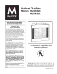
INSTALLER/CONSUMER
SAFETY INFORMATION
™
Read and save
these instructions.
This book contains your installation
instructions and should be kept in a
safe place. For you to realize all the
advantages and use of the reliable service that has been engineered into your
fireplace, you must carefully follow all of
the instructions contained in this book
regarding installation and operation of
the fireplace.
Vent-Free Gas Fireboxes
Model: UV36
These instructions should be read carefully in their entirety before beginning
installation of the fireplace.
It is suggested that you wear work
gloves and safety glasses to protect
your hands and eyes when installing
your fireplace. NOTE: Authorities having
jurisdiction (i.e. building inspectors, fire
marshals, etc.) should be consulted before installation to determine the need
to obtain a permit.
When installing the Blower Kit, it is
necessary to bring the power source to
the fireplace before walls are enclosed.
Refer to Blower Kit instructions.
These fireboxes are approved as universal fireboxes and can be paired
with any ANSI Z21.11.2 approved
vent-free log set. The vent-free log
manufacturer’s instructions - including their required dimensional
clearances for firebox size, - must be
followed.
Refer to the manual that is packed with
the log set for operating instructions.
CFM Specialty Home Products Unvented
Gas Logs VL24MN, VL24MP, VL24RN,
VL24RP, VFL34MN, VFL34MP, VFL34RN,
VFL34RP may be used with this firebox.
(Refer to Page 4)
Homeowner’s Installation and
Operating Instructions
78647
ADC36-3 cover
2/04
CFM Specialty Home Products
410 Admiral Blvd. • Mississauga, Ontario, Canada L5T 2N6 • 905-670-7777
www.majesticproducts.com • www.vermontcastings.com
INSTALLER: DO NOT DISCARD THIS MANUAL - Leave in fireplace for homeowner.
20007446 6/05 Rev. 4
UV36 Vent-Free Firebox
Table of Contents
This book contains your operating instructions and should be kept in a safe place. For you to realize all the advantages and use of the reliable service that has been engineered into your fireplace, you must carefully follow all of the
instructions contained in this book regarding installation and operation of the fireplace.
These instructions should be read carefully in their entirety before beginning installation of the fireplace.
It is suggested that you wear work gloves and safety glasses to protect your hands and eyes when installing your
fireplace.
NOTE: Authorities having jurisdiction (i.e. building inspectors, fire marshals, etc.) should be consulted before installation to determine the need to obtain a permit.
FAILURE TO FOLLOW THESE INSTRUCTIONS WILL VOID YOUR WARRANTY AND MAY PRESENT A FIRE
HAZARD.
Important Information .................................................................................................................. 3
Fireplace Dimensions .................................................................................................................. 4
Installation Instructions
Choosing the Location of Your Fireplace ............................................................................ 5
Gas Line ............................................................................................................................. 5
Drafts .................................................................................................................................. 5
Framing clearances ............................................................................................................ 5
Installing the Firebox .......................................................................................................... 6
Finishing the Fireplace ....................................................................................................... 7
Install Optional Outside Air Kit ............................................................................................ 8
Replacement Parts ..................................................................................................................... 10
Servicing ........................................................................................................................... 10
Accessories ................................................................................................................................. 10
Warranty ...................................................................................................................................... 11
UV36
Certified To
ANSI Z 21.91.2001
Ventless Fireboxes
for use with
any ANSI Z21.11.2
Unvented Room Heaters
Units:
UV36
2
GF1VU2
20007446
UV36 Vent-Free Firebox
Important Information
INSTALLER: Please leave these instructions with the
owner.
OWNER: Please retain these instructions for future
reference.
IMPORTANT: READ THESE INSTRUCTIONS CAREFULLY BEFORE OPERATING.
WARNING: Any change to this heater or its controls can be dangerous.
This heater shall not be installed in a confined
space or unusually tight construction unless provisions are provided fro adequate combustion and
ventilation air.
NOTES
• Due to high temperatures, the appliance should be
located out of traffic and away from furniture and
draperies.
•
Installation and repair must be done by a qualified service
person or gas appliance installer.
• The appliance must be inspected before use and at least
annually by a professional service person. More frequent
cleaning may be required due to excessive lint from
carpeting, bedding material, dust and pet hair, etc. It is
important that the control compartment, burners and circulating air passageways of the appliance be kept clean.
After servicing, always check for leaks.
• DO NOT place clothing or other flammable material on
or near the appliance.
• The installation must conform with local codes or, in the
absence of local codes, with the NATIONAL FUEL GAS
CODE, ANSI Z223/NFPA 54, latest edition.
• Any safety screen or guard removed for servicing an appliance must be replaced prior to operating the heater.
• DO NOT use this heater in recreational vehicles, bedrooms or bathrooms.
• If this is the ONLY gas appliance, we recommend a
minimum 200 pound cylinder with a fill gauge. Use
of a 100 pound cylinder is not recommended. Other
household gas appliances may require the tank size
to be larger. Do not operate the vent-free heater if the
fuel level in the propane tank is below 1/4 full.
• DO NOT use this heater if any part of it has been under
water. Immediately call a qualified technician to inspect the
appliance and replace any part of the control system and
any gas control which has been under water.
• Check local, state or city codes to determine if unvented heaters are permitted.
• This appliance may be installed in an after-market* manufactured “mobile” home where not prohibited by state or
local codes.
*After-market: Completion of sale, not for purpose of re-sale from the
manufacturer.
Children and adults should be alerted to the hazard of high
surface temperature and should stay away to avoid burns or
clothing ignition.
20007446
To avoid irreparable damage to the appliance or personal injury; matches, paper, garbage or any other material must not
be placed or thrown on top of the logs or into the flames.
To avoid personal injury, do not touch hot surfaces when
the appliance is operating.
Close supervision is necessary when the appliance is being
operated near children.
This appliance is intended to be used only for supplemental
heat. Do not use it routinely as a primary heat source.
Continuous operation could produce excessive humidity depending on construction characteristics and outdoor temperatures (below 20°F). Over time, this could cause condensation
to form and damage wall structures and exterior paint.
WARNING: Do not install glass doors on this fireplace.
WARNING: If the area in which the heater may be
operated is smaller than that defined as an unconfined space or if the building is of unusually tight
construction, provide adequate combustion and
ventilation air by one of the methods described in
the National Fuel Gas code, ANSI Z223.1/NFPA 54,
section 5.3 or applicable local codes.
WARNING: Do not allow fans to blow directly into
the fireplace. Avoid any drafts that alter burner
flame patterns.
WARNING: Do not use a blower insert, heat exchanger insert or other accessory not approved
for use with this heater.
WARNING: During manufacturing, fabricating
and shipping, various components of this appliance are treated with certain oils, films or bonding
agents. These chemicals are not harmful but may
produce annoying smoke and smells as they are
burned off during the initial operation of the appliance, possibly causing headaches and eye/lung
irritation. This is a normal and temporary occurrence.
The National Fuel Gas Code, ANSI Z223.1/NFPA
54 defines a confined space as a space whose
volume is less than 50 cubic feet per 1,000 Btu
per hour (4.8m3 per kw) of the aggregate input
rating of all appliances installed in that space and
an unconfined space as a space whose volume is
not less than 50 cubic feet per 1,000 Btu per hour
(4.8 m3 per kw) of the aggregate input rating of all
appliances installed in that space. Rooms communicating directly with the space in which the
appliances are installed, through openings not
furnished with doors, are considered a part of the
unconfined space.
3
UV36 Vent-Free Firebox
Any ANSI approved vent free log set with a maximum of
39,000 Btu/h or less that will fit into the firebox may be
used. (Fig. 1a)
20���"
The following CFM Specialty Home Products vent free
gas logs sets may be used:
11"
VL24MN, VL24MP, VL24RN, VL24RP, VFL34MN,
VFL34MP, VFL34RN, VFL34RP.
30���"
Fig. 1a Firebox dimensions.
Fireplace Dimensions
Rough
Opening
Depth
T258
firebox dimensions
5/28/04 djt
21���"
35���"
1/2"
14���"
35���"
Rough Opening Width 36���"
50
"
1/2” Clearance to combustibles not required at this point.
Gas Line Access
Rough
Opening
Height
Gas Line
Access
(Not used on
this model)
33���"
33���"
17"
8���"
8���"
8���"
3���"
7446
Gas Line Access
31���"
8���"
7���"
11���"
Outside Air Access
36"
1���"
7���"
3���"
Electrical Access
Fig. 1b UV36 specifications and framing.
7446
UV36 specs
2/04
4
20007446
UV36 Vent-Free Firebox
Installation Instructions
Choosing the Location for Your Fireplace
Figure 2 shows some of the many ways your fireplace
may be installed. Consider the traffic pattern in your
room and the location of doors and windows. Moving
air from ceiling fans, open doors and hot air grilles may
cause the flames to soot. If a disturbance is found that
affects the flames, it must be eliminated by turning off
the ceiling fan, closing the door or closing/moving the
hot air register. A corner location may be best where
space is limited.
Your fireplace weighs no more than some of your fine
furniture. If the fireplace is located near a load bearing wall, additional supports to the foundation will not
be necessary. HEAVY FACINGS SUCH AS BRICK,
STONE, ETC., MAY REQUIRE ADDITIONAL FOUNDATION SUPPORT.
ALTHOUGH THIS UNIT MAY BE INSTALLED ON
COMBUSTIBLE SURFACES, IT MUST NOT BE INSTALLED ON CARPET OR VINYL.
The clearances to sidewalls and ceiling that are shown
in Figure 3 must be considered when choosing the
location for the fireplace.
Room Divider
The fireplace may be placed directly on a combustible
floor, against a combustible wall at marked clearances
or on a raised wooden platform.
If the fireplace is to be installed on a raised wooden
platform, the platform must be a continuous level surface.
The fireplace must be secured in place so it cannot
shift positions. The nailing flanges on the sides of the
firebox make securing it to the framing easy. They were
designed to allow the installation of 1/2” wallboard or
plywood flush with the face of the fireplace.
Only the header (Fig. 1) may rest on the standoffs on
top of the firebox.
When the fireplace is installed over carpeting, vinyl tile
or any combustible material other than wood flooring,
it must be installed on a metal or wood panel extending its full width and depth. Alternatively - the carpeting, vinyl tile, etc., may be removed from beneath the
fireplace before installing.
COMBUSTIBLE MATERIALS MUST NOT BE INSTALLED OVER OR TOUCH THE BLACK FRONT
SURFACE OF THE FIREPLACE.
Clearances
Partial Room
Projection
To ensure a safe installation, the following instructions
must be carefully observed.
Full Room
Projection
Corner
Flush
T224
Fig. 2 Locating the fireplace.
Gas Line
T224
place fireplace
The gas line must be installed
by a licensed gas line
installer before framing in the2/04
fireplace.
Drafts
Do not locate the fireplace in high traffic areas or areas
exposed to high drafts and winds. Locate the fireplace
away from furniture and draperies.
20007446
Framing Clearances
1. Right and Left Sidewall Clearances: Clearances
from the side of the fireplace opening to any combustible wall should not be less than 2”.
2. Ceiling Clearances: The ceiling height should not
be less than 36” from the top of the fireplace opening.
3. Mantel and Wall Clearances:
A. Noncombustible materials must be used for all
wall coverings below the top standoffs of the
fireplace. (Fig. 3)
B. A combustible mantel may project 1” from the
wall 12” above the fireplace opening.
C. A combustible mantel must fall within the profile
that is shown in Figure 3.
4. Floor Clearances: No clearance is required if the
appliance is installed per these instructions.
5
UV36 Vent-Free Firebox
Combustible Mantel Clearances
Cabinet Installation
8"
6"
Noncombustible
or Void
24"
1"
3"
20"
12"
12"
Standoff
21"
Noncombustible
9"
9"
Canopy Installation
Hex Head Screws
17"
Canopy
Fig. 3 Combustible mantel clearances.
Installing the Firebox
21���"
This list of specific instructions will help you make certain that every installation operation is done correctly.
Complete the installation steps in the sequence shown.
1/2"
14���"
T233
clearances
2/04
36"
2” Minimum Clearance to
Side Wall or Mantel Leg
1/2” Clearance
Not Required at
this Point
14���"
Min.
36���"
32���"
36"
T233
LOCAL BUILDING CODES SHOULD BE CONSULTED
IN ALL CASES AS TO THE PARTICULAR REQUIREMENTS CONCERNING THE INSTALLATION OF FACTORY BUILT VENT FREE FIREPLACES.
Select the location for the fireplace by taking into consideration the factors previously outlined in the Choosing the Location section of this manual.
Step 1: Framing the Firebox
The entire fireplace can be elevated above the floor
to achieve a raised hearth effect. This can be done by
adding a small platform to achieve the desired height.
This platform must be a continuous surface extending
the full width and depth of the fireplace.
STOP! INSTALL CANOPY AT THIS TIME BY LOOSENING THE SCREWS LOCATED AT THE TOP
FRONT OF THE FIREPLACE. NEXT, SLIDE THE
SLOTTED FLANGE OF THE CANOPY UNDER THE
LOOSENED SCREWS, THEN RETIGHTEN THE
SCREWS TO SECURE THE CANOPY. (Fig. 3)
Step 2: Install the Firebox
Install the firebox into the framed opening by setting
it directly in front of the opening and sliding it into the
proper position.
Fig. 4 Framing dimensions.
6
T143
framing dimension
11/4/03 djt
20007446
UV36 Vent-Free Firebox
Step 3: Level the Firebox
Check the level of the firebox on the top edge of the
fireplace face. Shim if necessary.
Step 4: Secure the Firebox
Four (4) nailing flanges are supplied with the fireplace
(found on the fireplace hearth). To level the box and
secure it firmly in place, remove the nailing flange from
the hearth and install at the sides of the fireplace as
shown in Figure 5.
NOTE: The nailing flanges have two (2) sets of holes
to allow for adjustment for 1/2” or 5/8” offset of the face
of the unit. When installing the nailing flanges, choose
the set of holes on the nailing flange that fit with your
application.
NOTE: Refer to installation instructions for vent free
gas logs for gas connection, sizing, testing and all
safety information.
Nailing
Flanges
FP1532
Finishing the Fireplace
There are a wide variety of finishing materials available for your fireplace from formal wall treatments with
marble and mantels to rustic wood paneling, stone or
brick.
IT IS IMPORTANT THAT THE BLACK FACE OF THE
FIREPLACE NOT BE COVERED WITH ANY TYPE OF
COMBUSTIBLE MATERIAL.
Noncombustible facing materials such as marble, brick
or ceramic tile may overlap the black face of the fireplace up to the opening on either side of the fireplace.
Seal all joints between the black fireplace face and the
wall covering with a heat-resistant material such as rock
wool insulation or mortar. Be sure to use high temperature adhesive or mortar when anchoring brick, stone or
tile to the face of the fireplace. Check to see whether
man-made brick and stone are made of noncombustible
materials before using them on the face of the fireplace.
Some of these products contain combustible materials.
Combustible wall coverings such as paneling or wallboard may not overlap the black face of the fireplace.
The space between the wall covering and the fireplace
should be sealed with a heat-resistant material such as
rock wool insulation or mortar.
NOTE: An “L” shaped steel lintel must be installed
across the top of the firebox opening where facing
materials such as brick or stone are used on the face
of the firebox. It acts as a support/firestop. It should
be attached to the face of the fireplace with screws
and sealed to the fireplace with a heat-resistant sealer.
Refer to Figure 6 for finishing options.
Fig. 5 Secure firebox.
FP1532
Vent free
nailing flanges
10/04
20007446
7
UV36 Vent-Free Firebox
6a Wallboard with Marble, Slate or Tile Facing
6c Wallboard with Facing and Mantel
Finished Wall
Finished Wall
Noncombustible
Decorative Covering
Header
Noncombustible
Decorative Covering
Must be enclosed with a
noncombustible material.
T234
Header
Must be enclosed with a
noncombustible material.
The bottom mantel projection must be located a minimum of 9” above the fireplace opening. (Fig. 5b)
T235
T235Facing-Not Flush
6d Wallboard with
finishing w/facing,
and mantel
Finished Wall
2/04 Stud
T234
6b Brick or
Stone Facing
finishing w/facing
2/04
Finished Wall
Brick or
Stone Facing
Stud
Stud
Stud
Brick or
Stone Facing
Header
Header
Steel Lintel*
Steel Lintel*
Fig. 5 Finishing options.
T236
brick or stone
facing
2/04
T236
Install Optional Outside Air Kit
The AKU3 Outside Air Kit can be installed to bring combustion air to the heated room air. The air that is drawn
into the heated room air from outside the home or unheated area helps relieve the pressure in the home.
The duct termination should be located so it is exposed
to an out-of-doors opening at least 100 square inches.
If the duct termination must be located in a crawl space
or basement, be sure the termination area has 100
square inches of ventilation opening to outside air.
The duct termination must be located so it does not
compete for air flow with exhaust fans, gas vent hoods
or other air consuming devices or appliances. It must
not be obstructed by rafters, insulation materials or
other obstructions. The less restrictive the air supply,
the better the outside air kits will perform.
It is good practice to protect your hands and eyes
during installation by wearing work gloves and safety
glasses.
CAUTION: Do not install termination into a garage
or other area that could contain flammable liquids
or fumes, or into an attic space.
8
*Brick or stone facings lid up on the face of the fireplace must be
sealed to it with a steel lintel. Attach the lintel to the fireplace face
with sheet metal screws and seal it with a heat resistant sealer.
The projecting portion of the lintel should be imbedded in a mortar
T237
joint or mortared to the bottom
of the facing. The lintel acts as a
support and a firestop.
T237
facing not flush
2/04
Installation Instructions
Determine the location of the fireplace as described
in the fireplace installation manual. Then plan location
of the duct termination and the route of the duct run
between the fireplace and the duct termination.
Duct run must be limited to a maximum distance of 40’
(12.2m) from the fireplace pipe collar to duct termination. This will provide the least restriction to air flow. No
more than four (4) 90° elbows can be used. Duct run
may be horizontal, vertical, inclined or any combination of these. (Fig. 7) You are now ready to install the
Outside Air Kit.
1. Remove the screws retaining the outside air coverplate, if provided. (Located on the left side of front
open units, on backside of multisided units.) Discard
coverplate. (Fig. 8)
2. Secure the inlet collar assembly to the outer casing
with four screws (not provided). (Fig. 9)
3. Slide the duct over the collar and attach the duct
to the collar using the plastic tie straps or three (3)
screws (screws not provided). Continue attaching
the ducting together using three (3) screws at each
joint until you have installed sufficient duct to arrive
at your duct termination locations.
20007446
UV36 Vent-Free Firebox
should be caulked around its perimeter to assure a
tight seal. The rain cap opening should be positioned
downward. (Fig. 10)
The Outside Air Kit is now installed and ready for use.
Soffit Termination
Attic
Duct
Termination
Ceiling
40’ Max.
Duct Run
Duct
KT145
Fig. 9 Secure the inlet collar assembly.
Exterior Wall Termination
Caulking
KT145 Duct TerAKU reinstall
mination
cover plate
9/6/00 djt
Exterior Wall
Rain
Cap
40’ Max. Duct Run
Rain Cap
Duct Termination
Duct
FP1060
Fig. 7 Typical outside air installations.
Wall
FP1061
Fig. 10 Caulk and install duct termination/rain cap in place.
Cover Plate
FP1060
AKMST installation
7/6/00 djt
Operating Precautions and Instructions
FP1061
AKMST
Periodically inspect the duct termination for any blockrain cap
age. Correct if necessary.
7/6/00 djt
Operation is automatic. A slight negative pressure inside
the house will open the barometric flapper valve.
KT143
Fig. 8 Remove outside air cover plate and discard, retain
screws.
4. At the termination end, install the
duct termination.
KT143
This should be installed from the
outside
of plate
the
AKU cover
home. Cut a hole in the desired location approxi9/5/00 djt
mately 4¹⁄₂” (114mm) in diameter, caulk around the
hole, and slide the termination through the opening
from outside the home. The termination/rain cap
20007446
9
UV36 Vent-Free Firebox
4
1
5
2
3
CFM Specialty Home Products reserves the right to make changes in design, materials, specifications, prices and discontinue colors and products
at any time, without notice.
UV36 Vent-Free Firebox
Ref.
1.
2.
3.
4.
5.
Description
Refractory Side Brick (2 per fireplace)
Refractory Back Brick
Screen Panel Assy (2 per fireplace)
Canopy
Rod, Screen (2 per fireplace)
UV36
73501
74554
70317
71653
73652
7446
UV36 parts
8/04
Contact CFM Specialty Home Products for questions
concerning prices and policies covering replacement
parts. Parts may be ordered through your Majestic Fireplaces distributor or dealer.
You will need the correct name, part number and model
number of the appliance when ordering replacement
parts.
Should you need additional information beyond what
your dealer can furnish, contact:
Servicing
Repair and replacement work should only be done by a
qualified service person. Failure to have anual cleaning
and servicing performed will void the warranty.
Always shut off the gas supply and make sure the appliance is cool before beginning any service operation.
Always check for gas leaks after servicing.
CFM Specialty Home Products
410 Admiral Blvd.
Mississauga, Ontario
Canada L5T 2N6
Accessories
Outside Air Kit
10
AKU3
20007446
LIMITED LIFETIME WARRANTY
UV36 Vent-Free Firebox
PRODUCT COVERED BY THIS WARRANTY
All Vermont Castings gas stoves, gas inserts, and gas fireplaces, and all Majestic or Northern Flame brand gas fireplaces
equipped with an Insta-Flame Ceramic Burner, or standard steel tube burner.
BASIC WARRANTY
CFM Specialty Home Products (hereinafter referred to collectively as
the Company) warrants that your new Vermont Castings or Majestic
Gas Fireplace/Stove is free from manufacturing and material defects
for a period of one year from the date of purchase, subject to the
following conditions and limitations.
EXTENDED LIFETIME WARRANTY
The heat exchanger, where applicable, and combustion chamber
of every Vermont Castings or Majestic gas product is warranted for
life against through wall perforation. All appliances equipped with an
Insta-Flame Ceramic Burner have limited lifetime coverage on the
ceramic burner plaque. Warrantees are made to the original owner
subject to proof of purchase and the conditions and limitations listed
on this Warranty Document
•
•
•
•
COMPONENT WARRANTY
CAST IRON: All external and internal cast iron parts are warranted for a
period of three years.
Note: On porcelain enamel finished external parts and accessories
The Company offers no Warranty on chipping of enamel surfaces.
Inspect all product prior to accepting it for any damage to the
enamel.
The salt air environment of coastal areas or a high humidity
environment can be corrosive to the porcelain enamel finish. These
conditions can cause rusting of the cast iron beneath the porcelain
enamel finish, which will cause the finish to flake off.
Dye lot variations with replacement parts and/or accessories can
occur and are not covered by warranty.
GLASS DOORS: Glass doors are covered for a period of one year.
Glass doors are not warranted for breakage due to misuse or accident.
Glass doors are not covered for discoloration or burned in stains due to
environmental issues, or improper cleaning and maintenance.
BRASS PLATED PARTS AND ACCESSORIES: Brass parts should be
cleaned with Lemon oil only. Brass cleaners cannot be used. Mortar
mix and masonry cleaners may corrode the brass finish. The Company
will not be responsible for, nor will it warrant any brass parts which are
damaged by external chemicals or down draft conditions.
GAS VALVES: Gas valves are covered for a period of one year
•
•
•
•
•
•
ELECTRONIC AND MECHANICAL COMPONENTS: Electronic and
mechanical components of the burner assembly are covered for one
year. All steel tube burners are warranted for one year.
ACCESSORIES: Unless otherwise noted all components and CFM
Specialty Home Products company supplied accessories are covered
for a period of one year.
CONDITIONS AND LIMITATIONS
•
•
•
•
This new Vermont Castings or Majestic product must be installed by
a competent, authorized, service contractor. A licensed technician, as
prescribed by the local jurisdiction must perform any installation/service
work. It must be installed and operated at all times in accordance with
the Installation and Operating instructions furnished with the product.
Any alteration, willful abuse, accident, or misuse of the product shall
nullify this warranty.
This warranty is non-transferable, and is made to the original owner,
provided that the purchase was made through an authorized supplier
of the Company.
The customer must pay for any Authorized Dealer in-home travel fees
or service charges for in-home repair work. It is the dealers option
whether the repair work will be done in the customer’s home or in the
dealer’s shop.
If upon inspection, the damage is found to be the fault of the
manufacturer, repairs will be authorized at no charge to the customer
parts and/or labor.
20007446
•
Any part and/or component replaced under the provisions of this
warranty is covered for six months or the remainder of the original
warranty, whichever is longest.
This warranty is limited to the repair of or replacement of part(s) found
to be defective in material or workmanship, provided that such part(s)
have been subjected to normal conditions of use and service, after
said defect is confirmed by the Company’s inspection.
The company may, at its discretion, fully discharge all obligations
with respect to this warranty by refunding the wholesale price of the
defective part(s)
Any installation, labor, construction, transportation, or other related
costs/expenses arising from defective part(s), repair, replacement,
or otherwise of same, will not be covered by this warranty, nor shall
the Company assume responsibility for same. Further, the Company
will not be responsible for any incidental, indirect, or consequential
damages except as provided by law.
SOME STATES DO NOT ALLOW FOR THE EXCLUSION OR
LIMITATIONS OF INCIDENTAL AND CONSEQUENTIAL DAMAGES
OR LIMITATIONS ON HOW LONG AN IMPLIED WARRANTY
LASTS, SO THE ABOVE LIMITATIONS MAY NOT APPLY TO YOUR
CIRCUMSTANCES. THIS WARRANTY GIVES YOU SPECIFIC
RIGHTS AND YOU MAY HAVE OTHER RIGHTS WHICH VARY FROM
STATE TO STATE.
All other warranties-expressed or implied- with respect to the product,
its components and accessories, or any obligations/liabilities on the
part of the Company are hereby expressly excluded.
The Company neither assumes, nor authorizes any third party to
assume on its behalf, any other liabilities with respect to the sale of
this Vermont Castings or Majestic product
The warranties as outlined within this document do not apply to chimney
components or other non CFM Specialty Home Products accessories
used in conjunction with the installation of this product..
Damage to the unit while in transit is not covered by this warranty but
is subject to claim against the common carrier. Contact the dealer
from whom you purchased your fireplace/stove (do not operate the
appliance as this might negate the ability to process the claim with the
carrier).
The Company will not be responsible for:
a) Down drafts or spillage caused by environmental conditions such
as near-by trees, buildings, roof tops, hills, or mountains.
b) Inadequate ventilation or negative air pressure caused by
mechanical systems such as furnaces, fans, clothes dryers, etc.
This warranty is void if:
a) The fireplace has been operated in atmospheres contaminated by
chlorine, fluorine, or other damaging chemicals.
b) The fireplace has been subjected to prolonged periods of
dampness or condensation
c) Any damages to the fireplace, combustion chamber, heat
exchanger or other components due to water, or weather damage,
which is the result of but not limited to, improper chimney/venting
installation.
d) Any alteration, willful abuse, accident, or misuse of the product
has occurred.
IF WARRANTY SERVICE IS NEEDED…
1) Contact your supplier. Make sure you have your
warranty, your sales receipt, and the model/serial
number of your CFM Specialty Home Products
product.
2) DO NOT ATTEMPT TO DO ANY SERVICE WORK
YOURSELF.
11
CFM Specialty Home Products
410 Admiral Blvd. • Mississauga, Ontario, Canada L5T 2N6 • 905-670-7777
www.majesticproducts.com • www.vermontcastings.com