1
R
LASER PRINTER
SERVICE MANUAL
MODEL:HL-1060
© Copyright Brother 1997
All rights reserved.
No part of this publication may be reproduced in any form or by any means without permission in
writing from the publisher.
Specifications are subject to change without notice.
Trademarks:
The brother logo is a registered trademark of Brother Industries, Ltd.
Apple,the Apple Logo,and Macintosh are trademarks,registered in the United States and other
countries,and True Type is a trademark of Apple computer, Inc.
Epson is a registerd trademark and FX-80 and FX-850 are trademarks of Seiko Epson Corporation.
Hewlett Packard is a registered trademark and HP Laser Jet is a trademark of Hewlett Packard
Company.
IBM, IBM PC and Proprinter are registered trademarks of International Business Machines
Corporation.
Microsoft and MS-DOS are registered trademarks of Microsoft Corporation.
Windows is a registered trademark of Microsoft Corporation in the U.S. and other countries.
PREFACE
This service manual contains basic information required for after-sales service of the laser printer
(here- in-after referred to as "this machine" or "the printer"). This information is vital to the service
technician to maintain the high printing quality and performance of the printer.
This service manual covers the HL-1060 laser printer.
This manual consists of the following chapters:
CHAPTER I :
FEATURES AND SPECIFICATIONS
Features, specifications, etc.
CHAPTER II : THEORY OF OPERATION
Basic operation of the mechanical system, the electrical system and the electrical
circuits, and their timing information.
CHAPTER III : DISASSEMBLY AND REASSEMBLY
Procedures for disassembling and reassembling the mechanical system.
CHAPTER IV : MAINTENANCE AND TROUBLESHOOTING
Reference values and adjustments, troubleshooting image defects, troubleshooting
malfunctions, etc.
APPENDICES :SERIAL NO. DESCRIPTIONS, CONNECTION DIAGRAMS, PCB CIRCUIT
DIAGRAMS.
Information in this manual is subject to change due to improvement or re-design of the product. All
relevant information in such cases will be supplied in service information bulletins (Technical
Information).
A thorough understanding of this printer, based on information in this service manual and service
information bulletins, is required for maintaining its print quality performance and for improving the
practical ability to find the cause of problems.
CONTENTS
CHAPTER I
FEATURES AND SPECIFICATIONS ..........................................I-1
1. FEATURES .........................................................................................................................I-1
2. SPECIFICATIONS ..............................................................................................................I-3
2.1
2.2
2.3
2.4
2.5
2.6
2.7
Printing....................................................................................................................................... I-3
Functions ................................................................................................................................... I-3
Electrical and Mechanical .......................................................................................................... I-4
Paper Specification.................................................................................................................... I-5
Print Delivery ............................................................................................................................. I-6
Paper ......................................................................................................................................... I-6
Effective Printing Area ............................................................................................................... I-7
3. SAFETY INFORMATION ....................................................................................................I-9
3.1
3.2
3.3
Laser Safety (110 - 120V Model only) ....................................................................................... I-9
FDA Regulations (110 - 120V Model only) ................................................................................ I-9
Caution for Laser Product.......................................................................................................... I-10
CHAPTER II THEORY OF OPERATION ........................................................ II-1
1. ELECTRONICS..................................................................................................................II-1
1.1
1.2
1.3
1.4
1.5
1.6
General Block Diagram............................................................................................................. II-1
Main PCB Block Diagram ......................................................................................................... II-2
Main PCB.................................................................................................................................. II-3
1.3.1 CPU Core .................................................................................................................... II-3
1.3.2 ASIC ............................................................................................................................ II-4
1.3.3 ROM ............................................................................................................................ II-7
1.3.4 Optional ROM.............................................................................................................. II-7
1.3.5 DRAM .......................................................................................................................... II-8
1.3.6 Optional RAM .............................................................................................................. II-9
1.3.7 Optional Serial I/O ..................................................................................................... II-10
1.3.8 EEPROM ................................................................................................................... II-10
1.3.9 Reset Circuit.............................................................................................................. II-11
1.3.10 Parallel I/O................................................................................................................. II-11
1.3.11 Engine I/O.................................................................................................................. II-12
1.3.12 Paper Feed Motor Drive Circuit................................................................................. II-13
Driver PCB.............................................................................................................................. II-13
SW Panel PCB........................................................................................................................ II-13
Power Supply.......................................................................................................................... II-14
1.6.1 Low-voltage Power Supply........................................................................................ II-14
1.6.2 High-voltage Power Supply, SR PCB........................................................................ II-15
2. MECHANICS....................................................................................................................II-16
2.1
2.2
Overview of Printing Mechanism ............................................................................................ II-16
Paper Transfer........................................................................................................................ II-17
2.2.1 Paper Supply ............................................................................................................. II-17
2.2.2 Paper Registration..................................................................................................... II-17
2.2.3 Paper Eject ................................................................................................................ II-18
i
2.3
2.4
2.5
Sensors................................................................................................................................... II-19
2.3.1 Cover Sensor ............................................................................................................ II-19
2.3.2 Toner Empty Sensor ................................................................................................. II-19
Drum Unit................................................................................................................................ II-20
2.4.1 Photosensitive Drum ................................................................................................. II-20
2.4.2 Primary Charger ........................................................................................................ II-20
2.4.3 Developer Roller........................................................................................................ II-20
2.4.4 Transfer Roller........................................................................................................... II-20
2.4.5 Cleaner Roller............................................................................................................ II-20
2.4.6 Erase Lamp .............................................................................................................. II-20
Print Process .......................................................................................................................... II-20
2.5.1 Charging ................................................................................................................... II-20
2.5.2 Exposure Stage......................................................................................................... II-21
2.5.3 Developing................................................................................................................. II-22
2.5.4 Transfer ..................................................................................................................... II-22
2.5.5 Drum Cleaning Stage ................................................................................................ II-23
2.5.6 Erasing Stage ............................................................................................................ II-23
2.5.7 Fixing Stage............................................................................................................... II-23
CHAPTER III DISASSEMBLY AND REASSEMBLY.......................................III-1
1. SAFETY PRECAUTIONS..................................................................................................III-1
2. DISASSEMBLY FLOW......................................................................................................III-2
3. DISASSEMBLY PROCEDURE .........................................................................................III-3
3.1
3.2
3.3
3.4
3.5
3.6
3.7
3.8
3.9
3.10
3.11
3.12
3.13
3.14
3.15
3.16
3.17
3.18
3.19
3.20
Drum Unit................................................................................................................................. III-3
Output Tray ASSY ................................................................................................................... III-3
Top Cover ................................................................................................................................ III-4
MP Sheet Feeder 1 ASSY ....................................................................................................... III-4
MP Sheet Feeder 2 ASSY ....................................................................................................... III-7
Under Shoot ASSY .................................................................................................................. III-7
SR PCB / Relay PCB .............................................................................................................. III-9
Fixing Unit.............................................................................................................................. III-10
Scanner Unit .......................................................................................................................... III-14
Main PCB ASSY .................................................................................................................... III-15
Base Plate ASSY ................................................................................................................... III-15
Driver PCB ASSY .................................................................................................................. III-17
Low-voltage Power Supply PCB ASSY ................................................................................. III-18
High-voltage Power Supply PCB ASSY ................................................................................ III-19
Fan Motor ASSY ................................................................................................................... III-19
Drive Unit ............................................................................................................................... III-20
Main Motor ASSY .................................................................................................................. III-21
Gears and Solenoid ............................................................................................................... III-22
Paper Support........................................................................................................................ III-24
Extension Support Wire ......................................................................................................... III-24
4. PACKING ........................................................................................................................III-25
ii
CHAPTER IV MAINTENANCE AND TROUBLESHOOTING.......................... IV-1
1. INTRODUCTION.............................................................................................................. IV-1
1.1
1.2
Initial Check .............................................................................................................................IV-1
Basic Procedure ......................................................................................................................IV-2
2. CONSUMABLE PARTS ................................................................................................... IV-2
2.1
2.2
2.3
Drum Unit.................................................................................................................................IV-2
Toner Cartridge........................................................................................................................IV-2
Periodical Replacement Parts .................................................................................................IV-3
3. IMAGE DEFECTS ............................................................................................................ IV-4
3.1
3.2
3.3
3.4
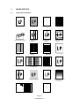
Image Defect Examples...........................................................................................................IV-4
Troubleshooting Image Defects...............................................................................................IV-5
Location of High-voltage Contacts and Grounding Contacts.................................................IV-19
Location of Feed Roller Shaft and Grounding Contacts ........................................................IV-20
4. PAPER JAM................................................................................................................... IV-21
5. TROUBLESHOOTING MALFUNCTIONS ...................................................................... IV-22
6. INSPECTION MODE...................................................................................................... IV-27
6.1
6.2
Incorporated Inspection Modes .............................................................................................IV-27
Error Codes ...........................................................................................................................IV-29
APPENDICES
1. Serial No. Descriptions...................................................................................................... V-1
2. Connection Diagram.......................................................................................................... V-2
3. Main PCB Circuit Diagram, (1/4) ....................................................................................... V-3
4. Main PCB Circuit Diagram, (2/4) ....................................................................................... V-4
5. Main PCB Circuit Diagram, (3/4) ....................................................................................... V-5
6. Main PCB Circuit Diagram, (4/4) ....................................................................................... V-6
7. Driver PCB Circuit Diagram............................................................................................... V-7
8. Switch Panel/Solenoid, Bin/Relay PCB Circuit Diagram ................................................... V-8
9. Low-voltage Power Supply PCB Circuit Diagram (110 - 240V).......................................... V-9
10. Low-voltage Power Supply PCB Circuit Diagram (220 - 240V)........................................ V-10
11. High-voltage Power Supply PCB Circuit Diagram............................................................ V-11
12. SR PCB Circuit Diagram ................................................................................................. V-12
iii
CHAPTER I FEATURES AND SPECIFICATIONS
1.
FEATURES
This printer has the following features:
1200dpi Resolution and 10ppm Printing Speed
600 dots per inch (dpi) with microfine toner and ten pages per minute
(ppm) printing speed (A4 or Letter size paper). The printer also
supports 1200 (H) x 600 (V) dots per inch (dpi) resolution for Windows
DIB graphics. ( It is recommended to add memory when printing in
1200 x 600dpi mode.)
User-Friendly Operation for Windows
The dedicated printer driver and TrueTypeTM-compatible fonts for
Microsoft® Windows 3.1 and Windows 95 are available on the floppy
disk supplied with your printer. You can easily install them into your
Windows system using our installer program. The driver supports our
unique compression mode to enhance printing speed in Windows
applications and allows you to set various printer settings including
toner saving mode, custom paper size, sleep mode, gray scale
adjustment, resolution, and so forth. You can easily setup these print
options in the graphic dialog boxes through the Printer Setup menu
within the Windows Control Panel.
Printer Status Monitor with Bi-directional Parallel Interface
The printer driver can monitor your printer’s status using bi-directional
parallel communications.
The printer status monitor program can show the current status of your
printer. When printing, an animated dialog box appears on your
computer screen to show the current printing process. If an error
occurs, a dialog box will appear to let you know what to correct. For
example: when your printer is out of paper, the dialog box will display
“Paper Empty” and instructions for the corrective action to take.
Versatile Paper Handling
The printer has two multi-purpose sheet feeders and a straight paper
path mechanism. From the front Feeder 1, you can load A4, letter,
legal, B5, A5, A6, and executive sizes of paper, and various types of
media including envelopes, postcards, organizer paper, or your custom
paper size. From the rear Feeder 2 you can load A4, letter, legal, B5
and executive sizes of paper. The front Feeder 1 also allows manual
paper loading, so you can also use labels and transparencies.
Environment-Friendly
Economy Printing Mode:
This feature will cut your printing cost by saving toner. It is useful to
obtain draft copies for proof-reading. You can select from two economy
modes 25% toner saving and 50% toner saving, through the Windows
printer driver supplied with your printer.
Sleep Mode (Power Save Mode):
Sleep mode automatically reduces power consumption when the
printer is not in use. The printer consumes less than 13W when in sleep
mode.
CHAPTER I -1
Low Running Cost:
The toner cartridge is separate from the drum unit. You need to replace
only the toner cartridge after around 2,200 pages, which is cost
effective and ecologically friendly.
Remote Printer Console Program for DOS
The utility program, Remote Printer Console (RPC), is available on the
floppy disk supplied with your printer. When you operate your computer
in the DOS (Disk Operating System) environment, this program allows
you to easily change the default settings of the printer such as fonts,
page setup, emulations and so on.
This program also provides a status monitor program, which is a
Terminate-and-Stay Resident (TSR) program. It can monitor the printer
status while running in the background and report the current status or
errors on your computer screen.
Popular Printer Emulation Support
This printer supports three printer emulation modes, HP LaserJet 5P,
Epson FX-850, and IBM Proprinter XL. The printer also supports
Auto-emulation switching between HP and Epson or HP and IBM. If you
want to select the printer emulation, you can do it using the Remote
Printer Console Program.
Enhanced Memory Management
The printer provides its own data compression technology in its printer
hardware and the supplied printer driver software, which can
automatically compress graphic data and font data efficiently into the
printer's memory. You can avoid memory errors and print most full
page 600dpi graphic and text data, including large fonts, with the
printer's standard memory.
CHAPTER I -2
2.
SPECIFICATIONS
2.1
Printing
Print method
Electrophotography by semiconductor laser beam scanning
Resolution
600 x 600dpi (for Windows/DOS)
300 x 300dpi (under Apple Macintosh using optional RS-100M)
1200 x 600dpi (Horizontal x Vertical)
(for Windows DIB graphics)
Print speed
10 page/minute (when loading Letter-size paper from the
multipurpose sheet feeder 1)
Warm-up
Max. 30 seconds at 23°C (73.4°F)
First print
15 seconds (when loading Letter-size paper from the multipurpose
sheet feeder 1)
Print media
Toner cartridge
Life Expectancy: 2,200 pages/cartridge (when printing A4 or letter size paper at 5% print coverage)
Drum unit, separated from toner cartridge
Life Expectancy: 20,000 pages/drum unit (4% coverage, continuous
printing) at 20 pages per job
8,000 pages at 1 page per job
Developer
2.2
Functions
CPU
IDT 79R3041-20J 20mhz
Emulation
Automatic emulation selection among HP LaserJet 5P, EPSON
FX-850, and IBM Proprinter XL
BR-Script (option)
Printer driver
Windows 95/WindowsTM 3.1 driver, supporting Brother Native
Compression mode and bi-directional capability
Optional Macintosh® QuickDraw driver (Standard in some
countries)
Interface
Bi-directional parallel interface (IEEE 1284 compatible)
A RS-422A/RS-232C serial interface is optionally available. (The
serial interface is a standard in some countries.)
Memory
2.0Mbytes with Data Compression Technology
Expandable up to 34Mbytes with the SIMM
Control panel
1 switch and 5 lamps
Diagnostics
Self-diagnostic program
CHAPTER I -3
2.3
Electrical and Mechanical
Power source
U.S.A. and Canada:
Europe and Australia:
Power consumption
Printing:
Standing by:
Sleep:
280W or less
60W or less
13W or less
Noise
Printing:
Standing by:
49dB A or less
38dB A or less
Temperature
Operating:
Storage:
10 to 32.5°C (59 to 90.5°F)
0 to 40°C (38 to 104°F)
Humidity
Operating:
Storage:
20 to 80% (non condensing)
10 to 85% (non condensing)
Dimensions (W x D x H)
Weight
AC 110 to 120V, 60Hz
AC 220 to 240V, 50Hz/60Hz
402 (W) x 439 (D) x 274 (H)
(when the output tray is closed and the Multi-purpose sheet
feeder is removed.)
Approx. 9.6kg (21.2lb.) including the drum unit and toner cartridge
CHAPTER I -4
2.4
Paper Specification
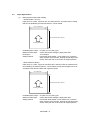
(1)
Multi-purpose sheet feeder loading
< Sheet Feeder 1 (Front)>
Paper size: A4, Letter, Legal, B5, A5, A6, and Executive, and other sizes of media
that can be handled by the feed mechanism, can be loaded.
69.8 to 229 mm
105 to 406mm (face down)
Feeding direction
Feedable paper weight:
Maximum load height :
Envelopes :
Setting method:
60 (16lb.) to 157 (42lb.) g/m2
22mm (200 sheets of 80g/m2 paper) letter size
10 envelopes
Pull the MP sheet feeder 1 cover toward you, insert the
stack of paper into the feeder, aligning the top edge of the
sheets, then push the cover back to its original position.
<Sheet Feeder 2 (Rear)>
Paper size: A4, Letter, Legal, B5, and Executive, and other sizes of media that can
be handled by the feed mechanism, can be loaded, except special papers such as
envelopes, OHP sheets, labels and organizer sheets.
90 to 229 mm
250 to 406mm (face down)
Feeding direction
Feedable paper weight: 60 (16lb.) to 157 (42lb.) g/m2
Maximum load height:
22mm (200 sheets of 80g/m2 paper) letter size.
Setting method:
Pull the MP sheet feeder 2 cover toward you, insert the
stack of paper into the feeder, aligning the top edge of the
sheets, then push the cover back to its original position.
CHAPTER I -5
2.5
Print Delivery
(1)
With the output tray opened
Tray capacity : Maximum 100 sheets (80g/m2), face-down only
(2)
With the output tray closed
Tray capacity : 1 sheet (80g/m2), face-down only
Note: Face down:
Environment :
2.6
Deliver the printed face of the paper downward.
23°C
Paper
(1)
Types of paper
<Sheet Feeder 1 (Front)>
(a)
Normal paper (60 to 157g/m2, specified types of high-quality paper)
• A4 size
• Letter size
• Legal size
• B5 size
• A5 size
• A6 size
• Executive size
• 9" envelop size (maximum printable area)
* The recommended types of plain paper are as follows:
Letter : Xerox 4200 (75g/m2)
A4 :
Xerox 80 Premier Paper (80g/m2)
(b)
Special paper (specified types)
• Labels
• Envelopes (DL, C5, COM10)
• Postcards
• Organizers (K, L, and J sizes of DAY-TIMERS)
<Sheet Feeder 2 (Rear)>
(a)
Normal paper (60 to 157g/m2, specified types of high-quality paper)
• A4 size
• Letter size
• Legal size
• B5 size
• Executive size
• The specified types of plain paper are as follows:
Letter : Xerox 4200 (75g/m2)
A4 :
Xerox 80 Premier Paper
CHAPTER I -6
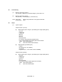
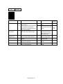
(2)
Paper feed conditions
Type
Name
60 to 80 g/m
Normal paper (cut sheet)
Feeder
Feeder 1
Feeder 2
2
2
80 g/m paper (Legal)
157 g/m
2
Labels
{
{
{
{
{
{
{
{
{
{
(200 sheets)
(200 sheets)
(100 sheets)
(100 sheets)
(30 sheets)
(30 sheets)
✕
(50 sheets)
Special paper (cut sheet)
Envelopes
✕
(10 sheets)
Postcards
✕
(30 sheets)
Organizers
✕
(10 sheets)
2.7
Manual feed
{
{
{
{
{
{
{
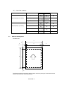
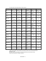
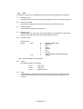
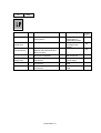
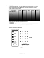
Effective Printing Area
Printable area
A
F
E
B
C
E
D
F
The effective printing area means the area within which the printing of all the data received
without any omissions can be guaranteed.
CHAPTER I -7
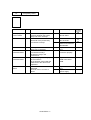
The table below shows the effective printing areas.
Size
A4
Letter
Legal
B 5 (JIS)
B 5 (ISO)
Executive
A5
A6
Organizer
(J size)
Organizer
(K size)
Organizer
(L size)
COM-10
MONARCH
C5
DL
A
210.0mm
8.27”
(2,480 dots)
215.9mm
8.5”
(2,550 dots)
215.9mm
8.5”
(2,550 dots)
182.0mm
7.16”
(2,149 dots)
176.0mm
6.93”
(2,078 dots)
184.15mm
7.25”
(2,175 dots)
148.5mm
5.85”
(1,754 dots)
105.0mm
4.13”
(1,240 dots)
69.85mm
2.75”
(825 dots)
95.25mm
3.75”
(1,125 dots)
139.7mm
5.5”
(1,650 dots)
104.78mm
4.125”
(1,237 dots)
98.43mm
3.875”
(1,162 dots)
162mm
6.38”
(1,913 dots)
110mm
4.33”
(1,299 dots)
B
297.0mm
11.69”
(3,507 dots)
279.4mm
11.0”
(3,300 dots)
355.6mm
14.0”
(4,200 dots)
257.0mm
10.12”
(3,035 dots)
250.0mm
9.84”
(2,952 dots)
266.7mm
10.5”
(3,150 dots)
210.0mm
8.27”
(2,480 dots)
148.5mm
5.85”
(1,754 dots)
127.0mm
5.0”
(1,500 dots)
171.45mm
6.75”
(2,025 dots)
215.9mm
8.5”
(2,550 dots)
241.3mm
9.5”
(2,850 dots)
190.5mm
7.5”
(2,250 dots)
229mm
9.01”
(2,704 dots)
220mm
8.66”
(2,598 dots)
C
203.2mm
8.0”
(2,400 dots)
203.2mm
8.0”
(2,400 dots)
203.2mm
8.0”
(2,400 dots)
170.0mm
6.69”
(2,007 dots)
164.0mm
6.46”
(1,936 dots)
175.7mm
6.92”
(2,075 dots)
135.8mm
5.35”
(1,604 dots)
93.0mm
3.66”
(1,098 dots)
57.15mm
2.25”
(675 dots)
82.55mm
3.25”
(975 dots)
127.0mm
5.0”
(1,500 dots)
92.11mm
3.63”
(1,087 dots)
85.7mm
3.37”
(1,012 dots)
150.0mm
5.9”
(1,771 dots)
98.0mm
3.86”
(1,157 dots)
D
288.5mm
11.36”
(3,407 dots)
271.0mm
10.67”
(3,200 dots)
347.1mm
13.67”
(4,100 dots)
248.5mm
9.78”
(2,935 dots)
241.5mm
9.5”
(2,852 dots)
258.3mm
10.17”
(3,050 dots)
201.5mm
7.93”
(2,380 dots)
140.0mm
5.51”
(1,654 dots)
118.5mm
4.66”
(1,400 dots)
162.98mm
6.42”
(1,925 dots)
207.43mm
8.17”
(2,450 dots)
232.8mm
9.16”
(2,750 dots)
182.0mm
7.16”
(2,150 dots)
220.5mm
8.68”
(2,604 dots)
211.5mm
8.33”
(2,498 dots)
E
3.4mm
0.13”
(40 dots)
6.35mm
0.25”
(75 dots)
F
4.23mm
0.17”
(50 dots)
Ç
6.01mm
0.24”
(71 dots)
Ç
6.35mm
0.25”
(75 dots)
6.01mm
0.24”
(71 dots)
Ç
6.35mm
0.25”
(75 dots)
Ç
Ç
Ç
Ç
6.01mm
0.24”
(71 dots)
Ç
(Note that the paper sizes indicated here should conform to the nominal dimensions
specified by JIS.)
A4 paper must accommodate 80 characters printed in pica pitch (203.2 mm).
The dot size is based on 300 dpi resolution.
CHAPTER I -8
Ç
Ç
Ç
Ç
Ç
Ç
Ç
Ç
Ç
Ç
Ç
Ç
Ç
Ç
3.
SAFETY INFORMATION
3.1
Laser Safety (110 - 120V Model only)
This printer is certified as a Class 1 laser product under the US Department of Health and
Human Services (DHHS) Radiation Performance Standard according to the Radiation
Control for Health and Safety Act of 1968. This means that the printer does not produce
hazardous laser radiation.
Since radiation emitted inside the printer is completely confined within the protective
housings and external covers, the laser beam cannot escape from the machine during any
phase of user operation.
3.2
FDA Regulations (110 - 120V Model only)
The US Food and Drug Administration (FDA) has implemented regulations for laser
products manufactured on and after August 2, 1976. Compliance is mandatory for
products marketed in the United States. One of the following labels on the back of the
printer indicates compliance with the FDA regulations and must be attached to laser
products marketed in the United States.
The label for Japanese manufactured products
MANUFACTURED:
BROTHER INDUSTRIES, LTD.
15-1, Naeshiro-cho, Mizuho-ku, Nagoya 467, Japan.
This product complies with FDA radiation
performance standards, 21 CFR Subchapter J.
The label for US manufactured products
MANUFACTURED:
BROTHER INDUSTRIES (USA) INC.
2950 Brother Blud., Bartlet, TN 38133, U.S.A.
This product complies with FDA radiation
performance standards, 21 CFR Subchapter J.
Fig. 1.1
CHAPTER I -9
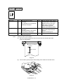
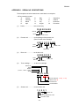
3.3
Caution for Laser Product (Warnhinweis für Laserdrucker)
CAUTION:
CAUTION:
ACHTUNG:
(1)
When the machine during servicing is operated with the cover open, the
regulations of VBG 93 and the performance instructions for VBG 93 are
valid.
In case of any trouble with the laser unit, please replace the laser unit itself.
To prevent direct exposure to the laser beam, do not try to open the
enclosure of the laser unit.
Im Falle von Störungen der Lasereinheit muß diese ersetzt werden. Das
Gehäuse der Lasereinheit darf nicht geöffnet werden, da sonst
Laserstrahlen austreten können.
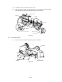
Location of the laser beam window.
Window
Fig. 1.2
(2)
Location of Caution Label for Laser Product. (200V only)
CLASS 1LASER PRODUCT
APPAREIL Å LASER DE CLASSE 1
LASER KLASSE 1 PRODUKT
Fig. 1.3
CHAPTER I -10
CHAPTER II THEORY OF OPERATION
1.
ELECTRONICS
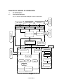
1.1
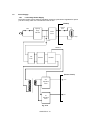
General Block Diagram
Optional ROM
(Max. 4Mbytes)
External Device
Fig. 2.1 shows a general block diagram of the HL-1060 printer.
Optional I/F Board
( RS-232C)
Optional RAM(SIMM)
(Max. 32Mbytes)
Control System
Expansion Memory I/O
Expansion I/O
Low-voltage Power
Supply Block
Interface Block
External Device
Expansion ROM I/O
Parallel
Video Control Block
Engine Control Block
Operation Block
(Operation Panel)
High-voltage Power
Supply Block
Erase Lamp
Drive Block
(Stepping Motor)
Laser Scanner Unit
Paper Tray Unit
Paper Feeder
Manual Feed
Drum Unit
Transfer Block
Fixing Unit
Developing
Block
Cleaner
Block
Drum
Charging
Block
Paper Eject Block
Paper Feed System
Toner Cartridge
Image Generation System
Fig. 2.1
CHAPTER II -1
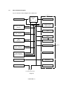
1.2
Main PCB Block Diagram
Fig. 2.2 shows the block diagram of the main PCB.
A S I C
CPU Core
R3041
Reset Circuit
BUS
Oscillator (40MHz)
INT
Address Decoder
DRAM Control
Program + Font ROM
(4Mbytes)
Timer
Optional ROM
(Max. 4Mbytes)
FIFO
RAM
DATA EXTENSION
(2Mbytes)
Parallel I/O
Option RAM (SIMM)
(Max. 32Mbytes)
Software Support
Option Serial I/O
(RS232C & RS422A)
EEPROM (512 x 8bits)
EEPROM I/O
Motor Driver
Engine Control I/O
To Panel Sensor PCB
Fig. 2.2
CHAPTER II -2
To PC
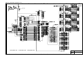
1.3
Main PCB
1.3.1
CPU Core
Fig. 2.3. shows the CPU circuit block on the main PCB.
The CPU is an IDT 79R3041-20J which is driven at a clock frequency of 20MHz. This clock
frequency is made by dividing the source clock frequency of 40.0MHz by two. The address
and data bus are both 32bits consisting of AD0 to AD31. The total addressable memory
space is 4Gbytes.
Fig. 2.3
CHAPTER II -3
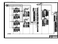
1.3.2
ASIC
The ASIC is composed of a Cell Based IC that contains the following functional blocks.
(1)
Oscillator circuit
Generates the main clock for the CPU by dividing the source clock frequency by two.
(2)
Address Generator
Generates the address bus by latching the AD bus with the ALE signal.
(3)
Address decoder
Generates the CS signal for each device.
(4)
DRAM control
Generates the RAS, CAS, WE, OE and MA signals for the DRAM and controls the
refresh processing (CAS before RAS self-refreshing method).
(5)
Interrupt control
Interrupt levels:
Priority
High
Low
9
8
7
6
5
4
3
2
1
TIMER 3 (Watch Dog)
MONITOR
FIFO
EXINT
TIMER 1
BD
SPARE
CDCC / BOISE / DATA EXTENTION
TIMER 2
Note: All the interrupts can be masked.
(6)
Timers
The following timers are included:
Timer 1
Timer 2
Timer 3
(7)
16-bit timer
10-bit timer
Watch-dog timer
FIFO
A 10Kbit FIFO is included. Data for one raster is transferred from the RAM to the
FIFO by DMA transmission and is output as serial video data. The data cycle is
6.13mhz.
CHAPTER II -4
(8)
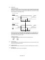
Parallel I/O
<Data receive Mode>
There are two modes in this unit. One is the CPU receive mode and the other is the
DMA receive mode. In the CPU receive mode the CPU receives the command data
from the PC, and after the CPU is switched to the DMA mode, it receives the image
data and writes it to the DRAM directly.
CPU Receive Mode
STROBE
BUSY
ACK
90 µsec
0.5 µsec
1.5 µsec
0.5 µsec
DMA Receive Mode
STROBE
BUSY
ACK
BUSY goes HIGH at the falling edge of the STROBE signal. The data (8 bits) from
the PC is latched into the data buffer at the rising edge of the STROBE signal. The
pulse width of ACK varies according to the speed MODE as shown above. BUSY
goes LOW on the rising edge of ACK.
<IEEE1284 support>
This supports the IEEE1284 data transfer with the following mode.
Nibble
mode
Byte
mode
ECP
mode
(9)
Data extension
This circuit extents the compressed image data which are received from the PC, and
writes the bit map data to the FIFO.
(10)
Software support
Supports 16 x 16 rotation, bit expansion, bit search, and decimal point conversion.
(11)
EEPROM I/O
One output port and one I/O port are assigned.
CHAPTER II -5
(12)
Engine control I/O
This I/O is used for the connection to the driver PCB. It controls the main motor,
solenoid, sensors, etc.
Fig. 2.4
CHAPTER II -6
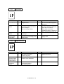
1.3.3
ROM
The program and the font data are stored in 4Mbytes of ROM. The ROM is composed of
two 16Mbit masked ROMs which are mounted in 42-pin IC sockets.
Fig. 2.5
1.3.4
Optional ROM
The program and the font data are stored in 4Mbytes of ROM. The ROM is composed of
two 16Mbit masked ROMs which are mounted in 42-pin IC sockets.
Fig. 2.6
CHAPTER II -7
1.3.5
DRAM
Four 4Mbit DRAM (x 8bit) are used as the printer memory.
Fig. 2.7
CHAPTER II -8
1.3.6
Optional RAM
A 32bit SIMM (72 pin) can be fitted as optional RAM. The main PCB has one slot and its
capacity is for SIMM from 1Mbytes to 32Mbytes.
Fig. 2.8
CHAPTER II -9
1.3.7
Optional Serial I/O
The interrupt of the serial I/O is input to the EXINT terminal of the ASIC, and recognized by
the CPU. A 32-byte space for a register is provided for this I/O, which is read and written to
by the CPU.
Fig. 2.9
1.3.8
EEPROM
The EEPROM is an X24C04F two-wire type with a 512 x 8bits configuration.
Fig. 2.10
CHAPTER II -10
1.3.9
Reset Circuit
The reset IC is a PST591DMT. The reset voltage is 4.2V (typ.) and the LOW period of the
reset signal is 50ms (typ.).
Fig. 2.11
1.3.10 Parallel I/O
Fig. 2.12 shows the parallel interface circuit.
Fig. 2.12
CHAPTER II -11
1.3.11 Engine I/O
Fig. 2.13 shows the engine interface circuit.
Fig. 2.13
CHAPTER II -12
1.3.12 Paper Feed Motor Drive Circuit
A DC motor is used for paper feeding.
Fig. 2.14
1.4
Driver PCB
The following parts are mounted on the driver PCB.
• Connectors ..................Low-voltage, high-voltage, solenoid, main motor, toner sensor,
laser, polygon motor, connector for main PCB
• Registration sensor
1.5
SW Panel PCB
The following parts are mounted on the SW panel PCB.
• Operation panel ........1 Key, 5 LEDs
CHAPTER II -13
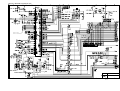
1.6
Power Supply
1.6.1
Low-voltage Power Supply
The power supply uses a switching regulation system to generate the regulated DC power
(+5V and +24V), which are converted from the AC line.
(Heater)
Thermal
Fuse
Lightning
Fuse
Surge
Heater
Absorber
Circuit
Lamp
Fuse
Feedback
Line
Filter
Rectifier
Oscillator
(Driver Circuit)
24V
24V
Regulation
Circuit
5V
Regulation
Circuit
Fig. 2.15
CHAPTER II -14
5V
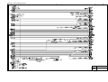
1.6.2
High-voltage Power Supply, SR PCB
This generates and outputs the voltages and currents for the charging, development and
transfer functions.
IC PROTECTOR
IP001
24VI
24VI
GND
Current
Regulator
Current
Regulator
24VI
GND
T1
T101
Transfer Roller
Voltage
Regulator
Supply
Roller
Photosensitive
Drum
VR201 VR202
Cleaner
Roller
Developing
Roller
Current
Regulator
Corona
Unit
T601 Q602
Voltage
Regulator
T701 Q702
GND
PAPER
SENSOR
Voltage
Regulator
PC001
Z301 VR301
Voltage
Regulator
VR401
Voltage
Regulator
VR501
Fig. 2.16
CHAPTER II -15
2.
MECHANICS
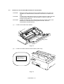
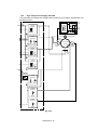
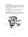
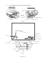
2.1
Overview of Printing Mechanism
MP Feeder 2 cover
Multi-purpose
Sheet Feeder 2
Papers
Multi-purpose Sheet Feeder 1
Manual Paper Path
Papers
MP Feeder 1 Cover
Paper Pick-up Roller
Paper Feed
Roller
Drum Unit
Photosensitive Drum
Pitch Roller
Hopper Plate
Blade
Transfer
Roller
Erase Lamp
Fixing Unit
Pressure Roller
Paper Pick-up Roller
Pinch Roller
Paper Feed Roller
Eject Roller
Hopper
Plate
Registration Sensor Lever
Eject Sensor
Actuator
Toner Cartridge
Polygon Mirror
Heat Roller
Developm
Thermistor
ent Roller Cleaning Roller
Laser Scanner
Toner
Empty
Sensor
Corona Wire
Supply Roller
Scanner Unit
Fig. 2.17
EL PCB
SW Panel PCB
Scanner Unit
Main Motor
Fan Motor
Solenoid Resist
Main Cotrol PCB
Driver
PCB
Primary Charger (Corona Wire)
Primary Charger (Grid)
Developer Roller
Transfer Roller
HighVoltage
Power
Supply
SR PCB
Relay PCB
Solenoid Bin
Thermistor (for Heat roller)
Toner
Empty
Sensor
PCB
Fig. 2.18
CHAPTER II -16
Toner Empty Sensor
Thermistor (for Tonner)
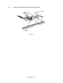
2.2
Paper Transfer
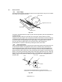
2.2.1
Paper Supply
The pick-up roller picks up one sheet of paper from the paper feeder every time it is rotated
and feeds it to the paper feed roller.
Pick-up roller
Papers
Registration sensor lever
Hopper plate
Separation pad
Fig. 2.19
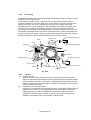
The paper is gripped between the pick-up roller and the separation pad and separated into
individual sheets.
The pick-up roller is directly connected to the sector gear, whose rotation is forcibly
stopped by the gear stopper; when the pick-up solenoid is activated, the clutch mechanism
is engaged by the solenoid action and the sector gear is driven; when it has completed one
full turn its rotation is stopped again by the gear stopper. The paper drawn out by the
pick-up roller pushes against the top of form sensor lever and the paper top
position/absence of paper is detected by sensing the motion of the lever.
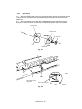
2.2.2
Paper Registration
When paper picked up from the multi-purpose sheet feeder (MPF) pushes against the top
of form sensor actuator, the registration sensor lever is caused to turn, and the photo
sensor detects this motion. When this signal from the sensor is detected the paper feed
roller is stopped temporarily by the clutch. The paper is fed to the nip point between the
paper feed roller and the pinch roller in the multi-purpose sheet feeder, and the skew of the
paper is corrected by pushing the leading edge of the paper against the nip point. When the
paper feed roller starts to be rotated again when it is released by the clutch, paper with the
leading edge correctly aligned, is fed by the paper feed roller and is transported to the
transfer roller.
Pinch roller
Paper
Transfer roller
Paper feed roller
Drum
Clutch mechanism (engaged/released by the solenoid assembly)
Released when the solenoid is ON and engaged when the solenoid is OFF.
Fig. 2.20
CHAPTER II -17
2.2.3
Paper Eject
The completion of paper eject is detected in the following manner:
(a)
When the leading edge of the paper pushes down the eject sensor actuator located
in the fixing unit, the photo sensor (photo interrupter) is opened and detects the start of
paper eject.
(b)
When the trailing edge of the paper has passed through the paper eject sensor
actuator, the photo sensor is closed and the completion of paper eject is recognized.
Transfer roller
Pressure roller
Eject sensor actuator
Eject roller
Drum
Heat roller
Fig. 2.21
Eject sensor actuator
,
,
Paper
Sensor
High-voltage power
supply PCB
Eject sensor actuator
Sensor
Fig. 2.22
CHAPTER II -18
2.3
Sensors
2.3.1
Cover Sensor
Detects opening and closing of the top cover.
Top Cover
Cover Switch
Fig. 2.23
2.3.2
Toner Empty Sensor
Detects if there is toner in the toner cartridge. It also detects whether or not the drum unit is
installed. (The toner cartridge is installed in the drum unit).
Toner Empty
Sensor
Fig. 2.24
CHAPTER II -19
2.4
Drum Unit
2.4.1
Photosensitive Drum
Generates the latent electrostatic image and develops the image on the drum surface.
2.4.2
Primary Charger
Forms a uniform charge on the drum surface.
(1)
Corona wire
Generates the ion charge on the drum.
(2)
Grid
Spreads the ion charge evenly over the drum surface.
2.4.3
Developer Roller
Develops the latent electrostatic image on the drum surface by the addition of the toner.
2.4.4
Transfer Roller
Transfers the toner image to the paper from the drum surface.
2.4.5
Cleaner Roller
Removes and recycles the toner remaining on the drum surface.
2.4.6
Erase Lamp
Discharges the electrostatic latent image on the drum.
2.5
Print Process
2.5.1
Charging
The drum is charged to approx. +1000V by an ion charge which is generated by the primary
charger. The charge is generated by ionization of the corona wire, which has a DC bias
from high-voltage power supply applied to it. The flow of the ion charge is controlled by the
grid to ensure it is distributed evenly on the drum surface. The drum sleeve is regulated to
approx. 280V by the voltage regulator.
280V
Passive Type
Voltage Regulator
-
Voltage
Regulator
+ + + -- +
++ - - - ++ + +
1000V
+ +
+ +
+ + +
+
+ ++
Aluminum drum sleeve
Drum
Organic Photoconductor layer
Grid
HVPS
Corona wire
Fig. 2.25
The primary charge uses a corona wire, but since the drum is positively charged, only less
than 1/10 of the usual quantity of ozone is generated compared with the negatively charged
drum. The level of ozone expelled from the printer is therefore not harmful to the human
body. Applicable safety standards have been complied with.
CHAPTER II -20
2.5.2
Exposure Stage
After the drum is positively charged, it is exposed to the light emitted from the laser unit.
Laser Beam
Drum
Paper
Laser beam
f lens
Laser detector
Polygon mirror
Laser diode
Motor
Lens
Fig. 2.26
The area exposed to the laser beam is the image to be printed. The surface potential of the
exposed area is
reduced forming the electrostatic image to be printed.
Surface Potential (V)
1 Cycle of drum
1
+1000
2
3
4
1
Primary charging
2
Laser beam exposure and developing
(a) Unexposed area
( Non image area )
(b) Exposed area
( Image area )
3
Transfer the image to paper
4
Erase the residual potential
(a)
+700
(b)
+400
Drum +300
Sleeve
Time
Fig. 2.27
CHAPTER II -21
2.5.3
Developing
Developing causes the toner to be attracted to the electrostatic image on the drum so as to
transform it into a visible image.
The developer consists of a non-magnetic toner. The development roller is made of
conductive rubber and the supply roller which is also made of conductive sponge rotate
against each other. The toner is charged and carried from the supply roller to the
development roller. The toner adheres to the development roller and is conveyed to the
drum at an even thickness controlled by the blade. The toner is nipped between the
development roller and the drum and developed onto the latent image on the drum. The
electrostatic field between the drum and the development roller, which is DC-biased from
the high-voltage power supply, creates the electrostatic potential to attract toner particles
from the development roller to the latent image area on the drum surface.
(a) Transfer process [ON]
Transfer roller
Blade
Toner
Separator
(b) Cleaning process [ON]
Auger
Drum
Erase lamp
Develop housing
(a) Collecting process
Supply roller
DC-bias
SR-bias
Development roller
(b) Discharging process
Cleaning roller
Charger
Fig. 2.28
2.5.4
Transfer
(a) Transfer process
After the drum has been charged and exposed, and has received a developed
image, the toner formed is transferred onto the paper by applying a negative charge
to the backside of the paper. The negative charge applied to the paper causes the
positively charged toner to leave the drum, and adhere to the paper. As a result, the
image is visible on the paper.
(b)
Cleaning process of transfer roller
If the toner is not transferred onto the paper perfectly, it is possible that there may be
residual toner on the drum which will adhere to the transfer roller. The transfer
voltage charges to a positive voltage during non-printing rotation of the drum.
Therefore the transfer roller is cleaned by returning the positive charged toner
adhered on the transfer roller onto the photo-conductive drum.
CHAPTER II -22
2.5.5 Drum Cleaning Stage
In the image transfer stage, not all the toner on the photosensitive drum is transferred onto
the paper but some remains on the drum. In the drum cleaning stage, the drum surface is
cleaned by the cleaning roller, so that residual toner on the drum surface is removed and
collected on the cleaning roller itself. The residual toner on the cleaning roller will be
discharged to the drum when starting or non-printing time. The toner will be collected by the
developing roller and reused (for further developing).
2.5.6
Erasing Stage
Before the cleaning stage, the drum surface is exposed to the light emitted from the erase
lamp. (LED lamp) This stage prepares the drum by decreasing its surface voltage
uniformly, ready to receive uniform change in the primary charging stage.
,
,,,,,,,,,
,
,
,
,
,,,,,,,,,
,,,,,,,,,
,
,
,
,,
2.5.7
Fixing Stage
An image transferred on paper by static electricity is fixed by heat and pressure when
passing through the heat roller and the pressure roller in the fixing unit. The thermistor
ASSY keeps the surface temperature of the heat roller constant by detecting the surface
temperature of the heat roller and turning on or off the halogen heater lamp. The cleaner
ASSY HR eliminates toner stains on the surface of the heat roller.
Pressure roller
Cleaner ASSY HR
,,,,
,,,,
Thermistor ASSY
Halogen heater lamp
Heat roller
Cleaner ASSY
Fig. 2.29
CHAPTER II -23
CHAPTER III DISASSEMBLY AND REASSEMBLY
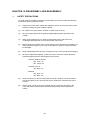
1.
SAFETY PRECAUTIONS
To avoid creating secondary problems by mishandling, be careful to follow the following
precautions during maintenance work.
(1)
Always turn off the power switch and unplug the power cord from the power outlet
before accessing any parts inside the printer.
(2)
Be careful not to lose screws, washers, or other parts removed.
(3)
Be sure to apply grease to the gears and applicable positions specified in this
chapter.
(4)
When using soldering irons or other heat-generating tools, take care not to
accidentally damage parts such as wires, PCBs, and covers.
(5)
Before handing any PCBs, touch a metal portion of the equipment to discharge any
static electricity charge on your body, or the electronic parts or components may
be damaged.
(6)
When transporting PCBs, be sure to wrap them in the correct protective packaging.
(7)
Be sure to replace self-tapping screws correctly, if removed. Unless otherwise
specified, tighten screws to the following torque values.
TAPTITE, BIND or CUP B
M3 : 7kgf • cm
M4 : 10kgf • cm
TAPTITE, CUP S
M3 : 8kgf • cm
SCREW
M3 : 7kgf • cm
M4 : 8kgf • cm
(8)
When connecting or disconnecting cable connectors, hold the connector bodies,
but not the cables. If the connector has a lock, release the connector lock first to
unlock it.
(9)
After a repair, check not only the repaired portion but also all connectors, also
check that other related portions are functioning properly before operational
checks.
III-1
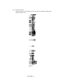
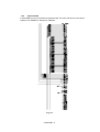
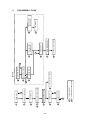
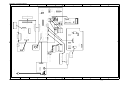
4
B
III-2
9
12
11
10
DRIVER PCB
BASE PLATE ASSY
MAIN PCB ASSY
EXTENSION SUPPORT WIRE
20
SR PCB / RELAY PCB
PAPER SUPPORT
7
A
19
A
SCANNER UNIT
C
FIXING UNIT
UNDER SHOOT ASSY
6
8
MP SHEET FEEDER ASSY
TOP COVER
OUTPUT TRAY ASSY
DRUM UNIT
5
3
2
1
BOTTOM
B
18
17
16
13
MAIN MOTOR ASSY
DRIVE UNIT
GEARS and SOLENOID
C
LOW-VOLTAGE
PS PCB ASSY
15
14
FAN MOTOR
HIGH-VOLTAGE
PS PCB ASSY
2.
DISASSEMBLY FLOW
3.
DISASSEMBLY PROCEDURE
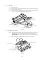
3.1
Drum Unit
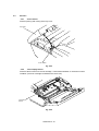
(1)
Open the top cover.
(2)
Lift out the drum unit.
Drum unit
Top cover
Main cover
Fig. 3.1
3.2
Output Tray ASSY
(1)
Press the hinges at the left and right ends of the output tray inwards to release the
output tray from the main cover.
Output tray
Output tray
Main cover
Fig. 3.2
III-3
3.3
Top Cover
(1)
Open the top cover.
(2)
Press the hinges at the left and right ends of the top cover inwards to release the
top cover from the main cover.
Note:
If it is impossible to release the top cover in the above way, press the side of the
top cover ( ) while pulling the side of the main cover ( ).
Top cover
Main cover
Top cover
Main cover
Fig. 3.3
3.4
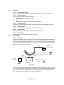
MP Sheet Feeder 1 ASSY
Note:
(1)
When disassembling the MP sheet feeder ASSY, the grease which smears your
fingers will stick to the separation pad or the paper pick-up roller, and then
spread to the paper and the drum unit. It might cause to appear black spots on
the printing page.
Slide the upper portion of MP sheet feeder 1 toward you and remove it.
MP sheet feeder 1
MP sheet feeder 2
Main cover
Fig. 3.4
III-4
(2)
Raise the pick-up roller cover ( ) and remove it ( ).
(3)
Remove the MP feeder cover ( ).
MP feeder cover
Pick-up
roller cover
Fig. 3.5
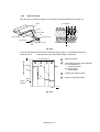
(4)
Remove the tray side covers R and L by releasing the three hooks inside each of
the covers as the following order.
Tray side cover R
<Releasing procedure>
1. Release the hook by hands.
2. Release the hook by using a screwdriver.
3. Release the hook by using a screwdriver.
4. Pull out the tray side
covers straight.
Top side cover L
Fig. 3.6
III-5
<HL-1060> PR98062
(5)
After removing the sector gear, paper feed bearing, and bearing 6, take off the
paper pick-up roller unit.
Bearing 6
Paper feed
bearing
Sector gear
Paper pick-up
roller unit
Fig. 3.7
(6)
Note:
Raise the pressure plate toward you and press both sides of the pad inward to
release it by pressing the separation pad holder. Then take off the spring.
If it is impossible to release the pressure plate in the above way, press the side of
the pressure plate ( ) while pulling the side of the sheet feeder ( ).
Pressure plate
Separation pad
Spring
Separation pad holder
Fig. 3.8
Note:
Be sure to replace the regist sensor actuator film together whenever replacing
the regist sensor actuator.
III-6
3.5
MP Sheet Feeder 2 ASSY
(1)
Remove the four screws.
(2)
Disassemble any other parts of MP sheet feeder 2 in the same way as described
for MP sheet feeder 1.
MP sheet feeder 2
Screws
Screw
Main cover
Fig. 3.9
3.6
Under Shoot ASSY
(1)
Disconnect the two cable harnesses from the relay PCB.
Under shoot ASSY
Cable harness
Relay PCB ASSY
Fig. 3.10
III-7
(2)
Remove the two screws.
(3)
Lift the rear portion of the under shoot assy to remove it.
Main cover
Under shoot ASSY
Fig. 3.11
Note:
Follow the number above in order when assembling.
Feed shaft roller
Plate spring
Fig. 3.11.1
III-8
3.7
SR PCB / Relay PCB
(1)
Remove the SR protect sheet.
(2)
Disconnect the connector of the SR harness ASSY connecting the SR PCB and
the driver PCB and remove the high-voltage cover.
SR protect sheet
High-voltage cover
SR harness ASSY
Main cover
SR PCB
Fig. 3.12
(3)
Disconnect the connector of the relay harness ASSY connecting the SR PCB and
the relay PCB and remove the two screws on the SR PCB, and remove the SR
PCB.
(4)
Remove the relay PCB.
(5)
Remove the two screws, and remove the electrode SR1, SR2.
Taptite, cup B M4x14
Taptite, cup B M4x14
Relay PCB
Taptite, cup B
Relay harness ASSY
SR PCB
Ground wire
Electrode SR2
Main cover
Electrode SR2
Fig. 3.13
III-9
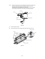
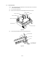
3.8
Fixing Unit
(1)
Remove the two screws.
(2)
Lifting the fixing unit, disconnect the two heater harnesses and the thermistor
connector on the EL PCB.
Screws
Fixing unit
Screws
EL PCB
Thermistor harness
Thermistor connector
Heater harness (White)
Fig. 3.14
(3)
Unhook the harness of the thermistor ASSY from the hook of the fixing unit.
(4)
Remove the screw.
(5)
Remove the thermistor ASSY.
(6)
Remove the cleaner ASSY.
Fixing unit
Cup B tight M3x14
Thermistor ASSY
Hook
Cleaner ASSY
Fig. 3.15
III-10
Follow instructions below when installing the thermistor in the fixing unit.
• Place the cleaner felt of the cleaner ASSY under the heat roller.
• Place the end of the thermistor on the heat roller.
• Insert the boss1 of the thermistor into the hole of the fixing unit frame.
• Do not place the thermistor on the boss2 of the fixing unit frame.
,
,
,
,
,
,
,
,
,
,
,,,,,,,,,,,
, , ,,,,
,
Note:
Thermistor
Boss2
Heat roller
,
,,
Boss1
Fixing unit frame
Cleaner ASSY
Fig. 3.16
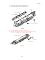
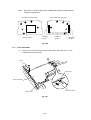
(7)
Remove the two screws.
(8)
Open the fixing unit cover along the open side of the fixing unit cover.
Fixing unit cover
Screws
Shaft
Fixing unit
cover
Pressure roller
Cleaner ASSY HR
Fixing unit frame
Fig. 3.17
III-11
PR98292
(9)
Release the cleaner lock from the cleaner ASSY HR.
(10)
Remove the cleaner ASSY HR from the fixing unit.
Fixing unit
Cleaner ASSY HR
Screw
Cleaner lock
Fig. 3.18
(11)
Release the right side of the paper eject roller shaft.
(12)
Remove the four eject pinch rollers and the pinch springs from the fixing unit
frame. Then, remove the pinch spring from each pinch roller.
Paper eject roller shaft
Pinch Spring
Eject Pinch Roller
Fig. 3.18a
III-12
Note:
Follow instructions below when installing the cleaner ASSY HR.
• Put the cleaner ASSY HR on the heat roller.
• Rotate the hook of the cleaner ASSY HR as shown in the figure to fit it into the
fixing unit frame.
• Insert the cleaner lock into the fixing unit frame.
Cleaner ASSY HR
,,,,,,,,
,,,,,,,,
Put the cleaner ASSY HR on
the heat roller and rotate it in this
direction to fit it into the hole.
Heat roller
Fixing unit frame
Cleaner lock
Fig. 3.19
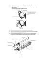
(13)
Remove the bind B tight 3 x 10 screw securing the connector plate.
(14)
Remove the connector plate from the fixing unit frame and loosen the other bind B
tight 3 x 10 screw securing the fixing unit cover.
(15)
After removing the idle gear 16 from the fixing unit frame, the heat roller can be
removed. You can then remove the halogen heater lamp from the heat roller.
Note:
Never touch the surface of the halogen heater lamp.
Heat roller
Halogen heater lamp
(Blue 100V, Red 200V)
Bind B tight M3x10
Bind B tight M3x10
Idle gear 16
Connector plate
Fixing unit frame
Fig. 3.20
III-13
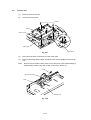
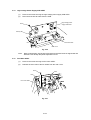
3.9
Scanner Unit
(1)
Remove the three screws.
(2)
Lift out the scanner unit.
Screws
Screw
Scanner unit
Main cover
Driver PCB
Fig. 3.21
(3)
Disconnect the three connectors from the driver PCB.
(4)
Remove the screw and the tape, and lift the toner sensor PCB from the scanner
unit.
Note:
Never touch the inside of the scanner unit or the mirror when disassembling or
reassembling. If there is any dirt or dust on the mirror, blow it off.
Screw
Toner sensor PCB
Tape
Scanner unit
Fig. 3.22
III-14
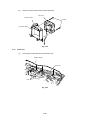
(5)
Turn the scanner unit upside down and remove the screw to release the toner
sensor harness.
Screw
Scanner unit
Toner sensor harness
Fig. 3.22-1
3.10
Main PCB ASSY
(1)
Remove the four screws.
(2)
Hold the hooks at left and right to pull out the main PCB ASSY.
Screw
Hook
Main PCB ASSY
Screws
Hook
Fig. 3.23
III-15
3.11
Base Plate ASSY
Note:
Prior to turning the printer upside-down, ensure that the drum unit has been
removed from the printer.
(1)
Turn the printer upside down.
(2)
Remove the five M4 and four M3 self tapping screws and one screw.
Taptite, cup M3x2
Screw
Taptite, cup M3x2
Taptite, bind M4x2
Taptite, cup M3x2
Base plate ASSY
Soundproof sponge
Fig. 3.24
(3)
Lift the base plate ASSY and remove the grounding screw.
Base plate ASSY
Ground wire
Screw
Low-voltage power
supply PCB ASSY
Fig. 3.25
III-16
Note:
See the Fig. 3.26 about the position installing the dumping material and the
soundproof sponge A,B.
<The inside of the base plate>
Dumping material
<The outside of the base plate>
Soundproof
sponge A
Soundproof
sponge B
Soundproof
sponge A
Fig. 3.26
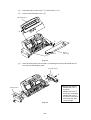
3.12
Driver PCB ASSY
(1)
Remove the screw securing the driver PCB ASSY. (Slide the PCB A from
underneath the main shield.)
A
Screw
Main shield
Driver PCB ASSY
Driver PCB ASSY
Insulation tape
Fig. 3.27
III-17
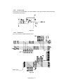
(2)
5
97-P-56
Disconnect the eleven connectors from the PCB. (Three connectors have already
been disconnected when removing the scanner unit.)
4
3
8
1
9
10
11
12
13
Driver PCB
ASSY
(Name of the harnesses)
1. SW panel harness
2. Scan motor harness
3. Toner harness
4. Laser harness
5. Fan motor harness
7. Main connector
8. High-voltage flat cable
9. Erase lamp harness
10. SR harness
11. Solenoid harness
12. Main motor harness
13. Low-voltage harness
2
7
Main frame
Fig. 3.28
Note 1: When reassembling, the cable connectors must be inserted securely into the
PCB connectors and the PCB must not be stressed by the harnesses.
Note 2: The connectors should be inserted by matching the housing color and the
number of pins.
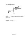
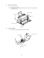
3.13
Low-voltage Power Supply PCB ASSY
(1)
Remove the screw securing the low-voltage power supply PCB ASSY.
(2)
Disconnect the two connectors for the heater harness and the LV harness from the
PCB.
LV harness
Low-voltage power supply ASSY
Heater harness
Screw
<200V only>
Main cover
Fig. 3.29
III-18
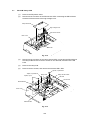
3.14
High-voltage Power Supply PCB ASSY
(1)
Remove the screw securing the high-voltage power supply PCB ASSY.
(2)
Disconnect the HV flat cable from the PCB.
High-voltage power
supply PCB ASSY
Screw
Density dial
HV flat cable
Main cover
Fig. 3.30
Note:
3.15
When reassembling, the flat side of the density dial shaft must be aligned with the
flat side of the density dial plastic adjustment cover.
Fan Motor ASSY
(1)
Remove the screw securing the fan motor ASSY.
(2)
Release the two hooks of the fan holder from the main cover.
Screw
Hook
Hook
Fan motor ASSY
Fig. 3.31
III-19
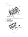
(3)
Remove the two screws securing the fan motor.
Fan motor
SW panel PCB
Screws
Fan motor holder
Fig. 3.32
3.16
Drive Unit
(1)
Unhook the heater harness from the drive unit.
Heater harness
Drive unit
Hook
Fig. 3.33
III-20
(2)
Release the hook to remove the gear cover.
(3)
Remove the six screws securing the drive unit. Lift the drive unit while pressing
and releasing the static removal plate spring on the drive unit.
Gear cover
Screws
Screws
Drive unit
Hook
Gear cover
Static removal
plate spring
Fig. 3.34
3.17
Main Motor ASSY
(1)
Remove the four screws securing the main motor ASSY.
Drive unit
Main motor ASSY
Screws
Fig. 3.35
III-21
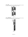
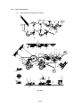
3.18
Gears and Solenoid
Apply grease to the points shown below.
K
E
G
H
E
M
L
A
H
C
H
A
A
C
A
A
Fig. 3.36
III-22
H
N
H
A
A
D
K
A
G
E
G
B
E
E
B
A
F
F
M, L
B
E
N
N
F
N
A
F
N
A
D
J
J
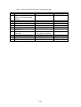
(1)
Note:
Sign
A
B
C
D
E
F
G
H
J
K
L
M
N
Follow instructions below when applying the grease.
When applying the grease
Before installing the gear.
After installing the bending
washer, and before installing
the gear.
Before installing the gear.
After installing the drive unit on
main body.
After installing the drive unit on
main body.
Before installing the gear.
Grease
Dow Corning LTD. EM-30L
Dow Corning LTD. EM-30L
Application amount
1 rice-grain size
1 rice-grain size
Dow Corning LTD. EM-30L
Dow Corning LTD. EM-30L
Dow Corning LTD. EM-30L
Dow Corning LTD. EM-D110
Dow Corning LTD. EM-30L
Dow Corning LTD. EM-30L
1 rice-grain size
5 rice-grain size
5 rice-grain size
Refer to the Fig. 3.36
1 rice-grain size
5 rice-grain size
Kanto Kasei LTD.
FLOIL GE334C or GE676
Dow Corning LTD. EM-30L
Dow Corning LTD. EM-D110
Dow Corning LTD. EM-D110
Dow Corning LTD. EM-D110
1/2 rice-grain size
III-23
1 rice-grain size
Refer to the Fig. 3.36
Refer to the Fig. 3.36
5 rice-grain size
3.19
Paper Support
(1)
Pull the paper support down toward you and pull both legs outwards to release it.
MP sheet feeder 1,2
Paper support
Fig. 3.37
3.20
Extension Support Wire
(1)
Raise the extension support wire toward you, press both legs inward to release it,
and then release the paper stopper from the wire.
Output tray
Paper stopper
Extension support wire
Fig. 3.38
III-24
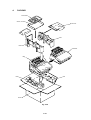
4.
PACKING
Documents
Carton, SF assy
Dust cover
Pad
Pad
PE sheet
Bag
Pad
Pad
Carton
Fig. 3.39
III-25
CHAPTER IV MAINTENANCE AND TROUBLESHOOTING
1.
INTRODUCTION
1.1
Initial Check
(1)
Operating environment
Check if :
• The source voltage stays within ±10% from the rated voltage shown on the rating
plate.
• The printer is installed on a solid, level surface.
• The room temperature is maintained between 10°C and 32.5°C. The relative
humidity is maintained between 20% and 80%.
• The printer is not located in a dusty place.
• The printer is not exposed to ammonia fumes or other harmful gases.
• The printer is not located in a hot or humid area (such as near water or a
humidifier).
• The printer is not exposed to direct sunlight.
• The room is well-ventilated.
• The printer is not placed where the ventilation hole of the printer is blocked.
(2)
Print paper
Check if :
• A recommended type of print paper is being used (if the paper is too thick or too
thin, or tends to curl, paper jams or paper feed problems may occur, or printed
images may be blurred).
• The print paper is damped. [If so, use fresh paper, and check whether the print
quality improves or not.]
(3)
Consumables
Check if :
• The Toner lamp is not lit on the control panel when a toner cartridge is installed in
the printer. [If the above lamp is lit, replace the cartridge with a new one. If blank
spots occur on printouts, take out the drum unit and slowly rock it to redistribute the
toner evenly.]
(4)
Others
Condensation:
When the printer is moved from a cold room into a warm room in cold weather,
condensation may occur inside the printer, causing various problems as listed
below:
• Condensation on the optical surfaces such as the scanning mirror, lenses, the
reflection mirror and the protection glass may cause the print image to be light.
• If the photosensitive drum is cold, the electrical resistance of the photosensitive
layer is increased, making it impossible to obtain the correct contrast when
printing.
• Condensation on the corona unit may cause corona charge leakage.
• Condensation on the hopper gate and separation pad may cause paper feed
troubles.
CHAPTER IV -1
If condensation has occurred, wipe the effected units or parts with a dry cloth.
If the drum unit is unpacked soon after it is moved from a cold room to a warm room,
condensation may occur inside the unit, which may cause incorrect images. Instruct the
user to allow the unit to come to room temperature before unpacking it. This will take one or
two hours.
1.2
Basic Procedure
If a malfunction or incorrect print appears, make an initial check following the basic
procedure below:
(1)
Check the error lamps following the inspection procedure described later in this
section. If no error lamps are lit, see Section 4 for troubleshooting information.
(2)
If any defective image output is found, follow the image defect fault descriptions in
this section.
2.
CONSUMABLE PARTS
2.1
Drum Unit
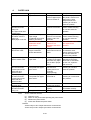
The Drum lamp is on when the drum unit is nearly at the end of its life.
Life expectancy:
Note:
2.2
20,000 pages at 20 pages per job
8,000 pages at 1 page per job
There are many factors that determine the actual drum life, such as temperature,
humidity, type of paper and toner that you use, the number of pages per print job,
etc..
Toner Cartridge
Toner low:
The Data and Alarm lamps blink once every five seconds.
Toner empty:
The Data and Alarm lamps blink once every second.
Life expectancy:
2,200 pages/a new toner cartridge
(when printing A4- or letter-size paper at 5% print coverage)
Note:
Toner life expectancy will vary depending on the type of average print job printed.
CHAPTER IV -2
2.3
Periodical Replacement Parts
No.
1
Description
Part No.
Qty
service life (number of print)
Remarks
(100,000)
120V
(100,000)
230V
Fixing Unit Y
UH3308001
1
(Cleaner ASSY HR)
(UH3310001)
1
Fixing Unit Y
UH3309001
1
(Cleaner ASSY HR)
(UH3310001)
1
2
Scanner Unit Y
1
(100,000)
3
MP sheet feeder 1 ASSY Y
1
(100,000)
(P pick-up roller shaft ASSY Y)
1
MP sheet feeder 2 ASSY Y
1
(P pick-up roller shaft ASSY Y)
1
4
Note:
(100,000)
The above table shows only estimated value, so these values are subject to
change without prior notice.
CHAPTER IV -3
3.
IMAGE DEFECTS
3.1
Image Defect Examples
I-1 Light
I-2 Dark
I-3 Completely blank
I-4 All black
I-5 Dirt on back of paper
I-6 Black vertical
streaks
I-6 Black vertical
streaks
I-7 Black horizontal
stripes
I-9 White vertical
streaks
I-10 Faulty
registration
I-11 Poor fixing
I-14 White spots
I-15 Black spots
I-8 Black vertical
streaks
o tnirp tset tuo tnirP o tnirp tset tuo tnirP tset tuo tnirp tset tuo tnirp tset tuo tnirP
Print out test print out test print out test Print out test print o Print out test print o
o tnirp tset tuo tnirP o tnirp tset tuo tnirP tset tuo tnirp tset tuo tnirp tset tuo tnirP
Print out test print out test print out test Print out test print o Print out test print o
o tnirp tset tuo tnirP o tnirp tset tuo tnirP tset tuo tnirp tset tuo tnirp tset tuo tnirP
Print out test print out test print out test Print out test print o Print out test print o
o tnirp tset tuo tnirP o tnirp tset tuo tnirP tset tuo tnirp tset tuo tnirp tset tuo tnirP
Print out test print out test print out test Print out test print o Print out test print o
o tnirp tset tuo tnirP o tnirp tset tuo tnirP tset tuo tnirp tset tuo tnirp tset tuo tnirP
Print out test print out test print out test Print out test print o Print out test print o
o tnirp tset tuo tnirP o tnirp tset tuo tnirP tset tuo tnirp tset tuo tnirp tset tuo tnirP
Print out test print out test print out test Print out test print o Print out test print o
o tnirp tset tuo tnirP o tnirp tset tuo tnirP tset tuo tnirp tset tuo tnirp tset tuo tnirP
Print out test print out test print out test Print out test print o Print out test print o
o tnirp tset tuo tnirP o tnirp tset tuo tnirP tset tuo tnirp tset tuo tnirp tset tuo tnirP
Print out test print out test print out test Print out test print o Print out test print o
o tnirp tset tuo tnirP o tnirp tset tuo tnirP tset tuo tnirp tset tuo tnirp tset tuo tnirP
Print out test print out test print out test Print out test print o Print out test print o
o tnirp tset tuo tnirP o tnirp tset tuo tnirP tset tuo tnirp tset tuo tnirp tset tuo tnirP
Print out test print out test print out test Print out test print o Print out test print o
o tnirp tset tuo tnirP o tnirp tset tuo tnirP tset tuo tnirp tset tuo tnirp tset tuo tnirP
Print out test print out test print out test Print out test print o Print out test print o
o tnirp tset tuo tnirP o tnirp tset tuo tnirP tset tuo tnirp tset tuo tnirp tset tuo tnirP
Print out test print out test print out test Print out test print o Print out test print o
o tnirp tset tuo tnirP o tnirp tset tuo tnirP tset tuo tnirp tset tuo tnirp tset tuo tnirP
Print out test print out test print out test Print out test print o Print out test print o
I-12 Image distortion
I-13 Faint print
I-16 Black band
I-17 Gray background
I-20 Horizontal lines
I-18 Hollow print
I-21 Light rain
Fig. 4.1
CHAPTER IV -4
I-19 Downward fogging
of solid black
3.2
Troubleshooting Image Defects
The following procedures should be followed in the event of specific image defects.
See subsection 3.3 for information about the location of the high-voltage contacts and
grounding contacts.
I-1
Light
Possible cause
Step
Check
Result
Remedy
Density dial
1
No
Toner sensing
failure
(printer side)
2
Is the density dial in the center
of the click position?
Can printing be started with the
drum unit removed?
Toner sensing
failure
(toner cartridge
side)
Drum
connection
failure
3
High-voltage
power supply
PCB failure
5
Driver PCB or
main PCB failure
6
Set it to the center
detect position.
Toner sensor failure.
Check if the toner
sensor needs
cleaning and check
the toner sensor
connection.
The wiper of the toner
cartridge is defective.
Replace the toner
cartridge.
Clean contact
electrodes both in the
printer body and on
the drum unit.
If the connection is
normal, replace the
high-voltage power
supply PCB.
Replace the driver
PCB or the main
PCB.
Scanner unit
failure
7
4
Yes
Is the problem solved when 4 or
5 pages are printed after the
toner cartridge is replaced with
a full one?
Is all the contacts (HV, GND)
connected with electrode when
the drum unit is installed?
Yes
Check the harness connection
between the high-voltage
power supply PCB and the
driver PCB.
Perform the same check as
step 5 above and also between
the driver PCB and the main
PCB.
Is the problem solved by
repealing the scanner unit?
No
CHAPTER IV -5
No
No
Yes
Replace the scanner
unit.
HV.GND
contacts
(Fig.4-5)
c
I-2
Dark
Possible cause
Step
Check
Result
Remedy
Density dial
1
Is the density dial at the center
click position?
No
Corona failure
(soiled wire)
2
Is the corona wire dirty?
Yes
Corona failure
(contact failure)
3
No
Drum unit failure
4
H.V. power
supply PCB
Main PCB
5
Driver PCB
7
Are the corona electrodes
between the printer body and
drum unit dirty?
Is the problem solved when the
drum unit is replaced?
Are there any disconnected
connectors?
Are there any disconnected
connectors?
Are there any disconnected
connectors?
Set it to the center
click position or
reasonable position.
Clean the corona wire
by using the wire
cleaner.
Clean both electrodes.
6
CHAPTER IV -6
Yes
No
No
No
Replace the drum unit
with a new one.
Replace the H.V.
power supply.
Replace the main
PCB.
Replace the driver
PCB.
HV.GND
contacts
(Fig.4-5)
j
h
I-3
Completely blank
Possible cause
Step
Developing bias
contact failure
1
Drum unit
2
Drum unit failure
3
Scanner harness
connection failure
4
Main/Driver PCB
connection failure
5
Scanner unit
failure
6
Check
Result
Remedy
Are the developing bias
contacts between the printer
body and drum unit dirty?
Are the drum shaft and drum
electrode of the printer body
connected correctly?
Yes
Clean the electrodes
at both sides.
Yes
Is the problem solved after the
drum unit is replaced?
Is the scanner harness
connected securely?
Is there any play in the
connection?
Are printing signals being input
to the scanner?
Is the problem solved after the
main PCB or the driver PCB
replaced?
Scanner interlock lever
damaged.
Scanner mirror is broken or
loose.
Yes
Clean the shaft and
the electrode.
Check the connection
between the shaft and
the electrode.
Replace the drum
unit.
Reconnect the
connector properly.
CHAPTER IV -7
No
Yes
Yes
Replace the main
PCB or the driver
PCB.
Yes
Replace the scanner
unit.
Replace the H.V.
power supply.
No
HV.GND
contacts
(Fig.4-5)
i
c
c
I-4
All black
Possible cause
Corona failure
Step
Check
Result
Remedy
1
Is the corona wire of the drum
unit broken?
Are the electric terminal springs
in the printer body and the
electrode on the bottom face of
the drum unit dirty?
Is the scanner unit connected
with the driver PCB correctly?
Yes
Replace the drum
unit.
Clean the terminals in
the printer and on the
drum.
2
Harness
connection
3
H.V. power
supply PCB
Ditto
4
Main PCB
6
Driver PCB
7
5
Is the problem solved after H.V.
power supply PCB replaced?
Perform the same check as in
step 3.
Is the problem solved after
main PCB replaced?
Is the problem solved after
driver PCB replaced?
CHAPTER IV -8
Yes
Yes
Yes
No
Yes
Yes
Check the harness
connection between
the scanner unit and
the driver PCB.
Replace the H.V.
power supply PCB.
Replace the panel
sensor PCB.
Replace the main
PCB.
Replace the driver
PCB.
HV.GND
contacts
(Fig.4-5)
h
I-5
Dirt on the back of paper
Possible cause
Fixing unit
Step
1
Dirt in the drum
unit
2
Note:
Check
Is the pressure roller dirty?
Is any other area in the printer
dirty?
Is the transfer roller dirty?
is the problem solved after the
drum unit replaced?
Result
Yes
Remedy
Clean the pressure roller.
(See the following note.)
Yes
Replace the drum unit
No
Replace the H.V. power supply
PCB.
Cleaning of the pressure roller
(1) Set three or more sheets of paper in MP sheet feeder 1 (or 2).
2)
Open the top cover.
(3) Turn on the power switch while holding down the switch on the control panel.
(4) Release the panel switch when the Drum lamp is on.
(5) Close the top cover.
(6) Hold down the panel switch until the Ready lamp is on, and then release the
switch.
(7)
Print three patterns; grid, zip and solid black.
(8)
Turn off the power switch with the top cover closed.
(9)
Set paper in the manual slot with the solid black side up.
(10) Turn on the power switch while holding down the switch on the control panel.
(11) Release the panel switch when the Drum lamp is on.
(12) Press the panel switch again and release it immediately.
(13) Print a page of test pattern while cleaning the pressure roller.
CHAPTER IV -9
I-6
Black vertical streaks
Possible cause
Step
Black and blurred vertical streaks
Check
Result
Remedy
Corona failure
1
Is the corona wire dirty?
Yes
Corona failure
2
Yes
Dirt in the paper
feed system
3
Yes
Clean the toner off.
Scratch on the
drum
Cleaning failure
4
Is the vertical block streak
about 10mm wide?
Is the corona wire cleaner not in
its home position?
Is the paper tray or feed system
on the drum unit soiled with
toner?
Is the drum surface scratched?
Clean the corona wire
with the wire cleaner.
Return the wire
cleaner to its home
position.
Yes
Scratch on the
heat roller
6
Replace the drum
unit.
Replace the drum
unit.
Replace the fixing
unit.
Note:
I-7
5
Is the drum surface dirty with
toner in streaks?
Is the surface of the heat roller
scratched?
Yes
Yes
HV.GND
contacts
(Fig.4-5)
j
Is you print the same pattern continuously, the drum will be worn away and black
vertical streaks appear on the paper.
Black and blurred horizontal stripes
Possible cause
Scratch on the
drum
Toner stuck on
the developer
roller
Scratch on the
fixing roller
SR PCB
Step
1
2
3
4
Check
Are the horizontal stripes at
94mm (OPC drum) intervals?
Are the horizontal stripes at
25mm (developer roller)
intervals?
Result
Yes
Are the horizontal streaks at
63mm (heat roller) intervals?
Is the problem solved after the
SR PCB replaced?
Yes
Print several sheet and see
what happens.
The problem will disappear
after a while. If not, replace the
drum unit.
Replace the fixing unit.
Yes
Replace the SR PCB.
CHAPTER IV -10
Yes
Remedy
Replace the drum unit.
I-8
Black vertical streaks (in the gray background)
Possible cause
Translucent
stain on the
scanner window
I-9
Step
1
Check
Are there any stains?
Result
Yes
Remedy
Clean the scanner window.
If it is not effective, replace the
scanner unit.
Result
Yes
Remedy
Clean the scanner window with
a dry tissue.
Replace the drum unit.
White vertical streaks
Possible cause
Scanner window
dirty
Transfer failure
I-10
Step
1
2
Check
Is the scanner window dirty?
Is the transfer roller scratched?
Yes
Faulty registration
Possible cause
Excessive paper
load
Print paper
Step
1
2
Ditto
3
Paper resist
sensor position
incorrect
4
Check
Is the paper loaded in the paper
feeder more than 22mm deep?
Is the specified weight of the
recommended paper being
used?
Is the first printing position
within ±1mm of the tolerance
specification?
Is the position of the paper
resist sensor normal?
CHAPTER IV -11
Result
Yes
No
Remedy
Instruct the user to keep paper
loads below 22mm in depth.
Instruct the user to use the
recommended types of paper.
Yes
Adjust the Y offset by using the
utility software supplied.
No
Reposition the sensor to the
correct position.
I-11
Poor fixing
Possible cause
Printing paper
Step
1
Check
Is thick paper more than 36lb
weight in use?
Result
Yes
Toner sensing
failure
2
Is the problem solved by
replacing the drum unit or the
toner cartridge?
(When printing is faint.)
Yes
Thermistor
failure
Low-voltage
power supply
PCB failure
3
Is the thermistor fitted
correctly?
Is the problem solved by
replacing the low-voltage power
supply PCB?
No
I-12
4
Yes
Remedy
Instruct the user to use paper of
the recommended weight and
thickness.
Toner is empty.
The toner sensing is defective,
clean the toner sensor.
If the wiper in the toner
cartridge is broken, replace the
toner cartridge with a new one.
Fit the thermistor correctly.
Replace the low-voltage power
supply PCB.
Image distortion
Possible cause
Scanner
Step
1
Scanner LD
emission failure
Scanner motor
rotation failure
Scanner
connection
failure
2
3
Check
Is the scanner unit secured to
the frame incorrectly?
Is there any play?
Is the laser diode or the laser
scanner motor defective?
Is the scanner harness
connected properly?
Is it coming loose?
CHAPTER IV -12
Result
Yes
Remedy
Secure the unit correctly and
tighten the screws.
Yes
Replace the scanner unit.
Yes
Connect the harness correctly.
I-13
Faint print
o tnirp tset tuo tnirP o tnirp tset tuo tnirP tset tuo tnirp tset tuo tnirp tset tuo tnirP
Print out test print out test print out test Print out test print o Print out test print o
o tnirp tset tuo tnirP o tnirp tset tuo tnirP tset tuo tnirp tset tuo tnirp tset tuo tnirP
Print out test print out test print out test Print out test print o Print out test print o
o tnirp tset tuo tnirP o tnirp tset tuo tnirP tset tuo tnirp tset tuo tnirp tset tuo tnirP
Print out test print out test print out test Print out test print o Print out test print o
o tnirp tset tuo tnirP o tnirp tset tuo tnirP tset tuo tnirp tset tuo tnirp tset tuo tnirP
Print out test print out test print out test Print out test print o Print out test print o
o tnirp tset tuo tnirP o tnirp tset tuo tnirP tset tuo tnirp tset tuo tnirp tset tuo tnirP
Print out test print out test print out test Print out test print o Print out test print o
o tnirp tset tuo tnirP o tnirp tset tuo tnirP tset tuo tnirp tset tuo tnirp tset tuo tnirP
Print out test print out test print out test Print out test print o Print out test print o
o tnirp tset tuo tnirP o tnirp tset tuo tnirP tset tuo tnirp tset tuo tnirp tset tuo tnirP
Print out test print out test print out test Print out test print o Print out test print o
o tnirp tset tuo tnirP o tnirp tset tuo tnirP tset tuo tnirp tset tuo tnirp tset tuo tnirP
Print out test print out test print out test Print out test print o Print out test print o
o tnirp tset tuo tnirP o tnirp tset tuo tnirP tset tuo tnirp tset tuo tnirp tset tuo tnirP
Print out test print out test print out test Print out test print o Print out test print o
o tnirp tset tuo tnirP o tnirp tset tuo tnirP tset tuo tnirp tset tuo tnirp tset tuo tnirP
Print out test print out test print out test Print out test print o Print out test print o
o tnirp tset tuo tnirP o tnirp tset tuo tnirP tset tuo tnirp tset tuo tnirp tset tuo tnirP
Print out test print out test print out test Print out test print o Print out test print o
o tnirp tset tuo tnirP o tnirp tset tuo tnirP tset tuo tnirp tset tuo tnirp tset tuo tnirP
Print out test print out test print out test Print out test print o Print out test print o
o tnirp tset tuo tnirP o tnirp tset tuo tnirP tset tuo tnirp tset tuo tnirp tset tuo tnirP
Print out test print out test print out test Print out test print o Print out test print o
Possible cause
Printer not level
Step
1
Drum unit
2
Scanner window
dirty
Scanner unit
failure
3
I-14
4
Check
Is the printer placed
horizontally?
Does the problem happened
immediately after replacing the
drum unit with a new one?
Is the window of the laser
scanner dirty?
Is the problem solved by
replacing the scanner unit?
Result
No
Check
Is the toner in the toner
cartridge almost empty?
Result
Yes
Yes
Yes
Yes
Remedy
Place the printer on a flat
surface.
Remove and shake the drum
unit horizontally with care.
Clean the scanner window with
a dry tissue.
Replace the scanner unit.
White spots
Possible cause
Toner cartridge
Step
1
Print paper
2
Is the problem solved after
change to specified of fresh
unpacked paper?
Environment
3
Check if the problem still
appears after the printer has
warmed up.
CHAPTER IV -13
No
Yes
Yes
Remedy
Shake the drum unit
horizontally. Replace the toner
cartridge with a new one.
Replace the drum unit.
Recommend the user to
change the paper.
(Damp (wet) paper might be
used.)
Replace the drum unit.
Advise the user of the specified
print environment.
I-15
Black spots
Possible cause
Drum unit
Step
1
Check
Are the spots at 94mm
intervals?
The problem is not solved after
printing a few pages.
Result
Yes
Fixing unit
2
Yes
SR PCB
3
Are the spots at 63mm
intervals?
And the problem is not solved
after printing a few pages.
Is the problem solved after the
SR PCB replaced?
Note:
Yes
Remedy
If toner remains stuck, wipe it
off gently with a cotton swab.
Replace the drum unit if the
OPC drum is scratched or
deteriorated (exposed).
(Refer to the following note.)
Check and clean the heat roller
with a cloth dampened with
alcohol.
Replace the fixing unit.
Replace the SR PCB.
Clean the drum unit as follows:
(1) Place the printing samples in front of the process unit, and find the exact
portion of image defect.
Position of smudge on
the drum
94mm interval
Fig. 4.2
(2) Turn the drum gear by finger while looking at the surface of the OPC drum.
Fig. 4.3
CHAPTER IV -14
(3) Wipe the surface of the photosensitive drum with a cotton swab until the dust
or paper powder on the surface toner lamp comes off.
Separator
Paper path
Cleaning roller
Toner cartridge
Photo sensitive drum
Fig. 4.4
Caution: Don't wipe the surface of the photosensitive drum with something sharp. (ballpoint pen etc.)
Use the cleaning liquid which is mixed ethyl alcohol and pure water at the rate of
each 50%.
CHAPTER IV -15
I-16
Black bank
Possible cause
Drum unit
Step
1
Check
Is the wire cleaner positioned at
its home position?
Result
No
Yes
I-17
Remedy
Return the wire cleaner to its
home position.
Replace the drum unit.
Gray background
Possible cause
Density dial
Step
1
Print paper
2
Check
Is the problem corrected by
adjusting the density dial?
Does the paper being used
meet the paper specification
(weight, etc.).
Result
Yes
No
Yes
Drum unit
3
Is the problem solved after
replacing the drum unit?
Yes
Remedy
Adjust the dial to the most
suitable position.
Recommend to change the
paper to a specified type of the
paper.
Recommend to change the
paper to a fresh pack paper.
Replace the H.V. power supply.
Replace the drum unit.
Note:
The following cases raise the possibility of this problem.
1.
2.
3.
The drum unit is at the end of its life.
There is dust or paper powder.
A large number of paper whose width is narrower than A4 is printed.
CHAPTER IV -16
I-18
Hollow print
Possible cause
Print paper
Step
1
Check
Is thick paper of more than 42lb
being used or extremely rough
surface paper?
Result
Yes
No
I-19
Possible cause
Drum unit
SR PCB
Remedy
Recommend to use the
specified type of paper.
Refer and compare with I-14.
Downward fogging of solid black
Step
1
2
Check
Is the problem solved after
replacing the drum unit?
Is the problem solved after
replacing the SR PCB?
CHAPTER IV -17
Result
Yes
Remedy
Replace the drum unit.
Yes
Replace the SR PCB.
I-20
Horizontal lines
Possible cause
Step
Check
Result
SR electrode
1
Yes
Clean both
electrodes.
SR connection
failure
2
No
Check the SR
connection.
Feed roller
3
Are the SR electrodes between
the printer body and the drum
unit dirty?
Are the SR electrodes between
the printer body and the drum
unit connected correctly?
Are the feed roller shaft and the
ground contact connected
correctly?
No
Check the
connection between
the shaft and the
ground contact.
I-21
HV.GND
contacts
(Fig.4-5)
Remedy
k
l
Light rain
Note:
Make the printer in the light rain test mode as follows before
checking;
1. Turn on the power switch and open the top cover.
2. Hold down the panel switch until all the lamps are on, and then
release the switch.
Possible cause
Drum unit failure
Step
1
SR PCB failure
2
High-voltage
power supply
PCB failure
3
**Note:
Check
Is the problem solved after
replacing the drum unit which
contains no more starter
sheet**?
Is the problem solved after
replacing the SR PCB?
Is the problem solved after
replacing the High-voltage
power supply PCB?
Result
Yes
Remedy
Replace the drum unit.
Yes
Replace the SR PCB.
Yes
Replace the High-voltage
power supply PCB.
Make sure to use the used drum unit which has already ejected the starter sheet.
It is not possible to find the drum unit failure if you use a new drum unit with the
starter sheet.
CHAPTER IV -18
3.3
Location of High-voltage Contacts and Grounding Contacts
Grounding contacts
c Drum shaft
High-voltage contacts
d Grounding wire
e For transfer
roller
Drum unit
f For cleaning
roller
k For supply roller
g For grid
i For development
roller
j Wire cleaner
h For corona wire
Fig. 4.5
To SR PCB
For development
roller
For supply roller
For corona wire
For cleaning roller
For transfer roller
Grounding wire
For corona wire
For drum
For drum
For cleaning
roller
For transfer
roller
For grid
Fig. 4.6
CHAPTER IV -19
For development
roller
3.4
Location of Feed Roller Shaft and Grounding Contacts
Feed shaft roller
For feed roller
Fig. 4.7
CHAPTER IV -20
4.
PAPER JAM
Problem
Jam at power on
Type of jam
Paper stuck
Cause
The paper feed
sensor of paper eject
sensor is turned on.
Top of paper stopped
at 20mm from the
fixing unit.
The paper feed roller
rotated twice.
Top of paper stopped
at 250mm from the
fixing unit.
Next paper is not fed.
No paper
The paper feed
sensor is not turned
on.
1) Jam caused by
paper length
considered longer than
400mm (16 inches).
2) Jam caused by
malfunction of the
regist sensor
1) The paper feed
sensor is not returned
properly, and is not
turned off.
2) The regist sensor
actuator is not
returned to the home
position.
The paper feed
sensor was turned off
earlier.
Top paper stopped at
the transfer roller.
Jam caused by paper
length considered
shorter than 80mm.
Paper was fed approx.
20mm transfer roller.
Jam caused by delay of
paper feed.
Top of paper stopped
at 17mm from the
contact point of the
heat roller and
pressure roller.
Top of paper stopped
at 35mm from the
contact point of the
heat roller and
pressure roller.
Jam occurred after
ejecting paper.
Top of paper stopped
at 20mm from the
fixing unit.
Jam caused paper is
not ejected from paper
eject sensor.
Note:
Jam caused paper is
not ejected from paper
eject sensor.
Same as above.
1) Cover open.
2) Bug
Due to the paper dust
or rubber of the paper
feed roller war, paper
was not fed in proper
timing.
Paper eject sensor
does not work
properly and is not
turned off.
(single printing)
Paper feed sensor is
not turned on.
Same as above.
(continuous printing)
1) Cover is not closed
properly.
2) Bug
Temp measure
Remove the paper inside
the printer. If there is no
paper exist, check
suspected sensors
referring to note and
clear the problem.
Check the paper feed
sensor motion referring
to note and clear the
problem.
1) Check the paper feed
sensor motion referring
to note and clear the
problem.
2) Attach the film onto
the regist sensor
actuator.
Malfunction of actuator
or hardware noise.
Check sensors referring
to note and clear the
cause of the problem.
Remove the paper dust
attached to the paper
feed roller. If the rubber
is worn out, replace it
with new one.
Check the sensor motion
referring to note and
clear the problem.
Check the sensor motion
referring to not and clear
the problem.
Same as above.
1) Check if the drum unit
is installed correctly.
2) Please inform BIL.
How to make the sensors
(1)
(2)
(3)
(4)
Open the cover.
Power on the printer while pressing the panel switch.
Release the panel switch.
Press and release the panel switch.
Results:
*Alarm Lamp is ON = Paper feed sensor is turned ON
*Drum Lamp is ON = Paper eject sensor is turned ON
IV-21
5.
TROUBLESHOOTING MALFUNCTIONS
When carrying out countermeasures for malfunctions as described in this section, check
connectors for contact failure before measuring the voltage at the specified connector pins.
M-1
No AC power supplied
Possible cause
Supply voltage
Step
1
Power plug
2
Fuse (F1, F2)
3
Wiring
4
M-2
Check
Is the correct voltage present at
the outlet?
Is the power cord securely
plugged into the outlet?
is the fuse blown?
Unplug the power supply plug.
Is there a broken wire between
the AC input connector of the
low-voltage power supply and
the power plug?
Result
No
No
Yes
Yes
Remedy
Inform the user that the correct
voltage is not supplied at the
outlet.
Plug the power cord securely
into the outlet.
If the fuse blows again
immediately after replacing the
low-voltage power supply PCB,
check that there is not a short
circuit somewhere in the AC
power supply line.
Replace the AC power cord.
No DC power supplied
Possible cause
AC power supply
Step
1
Wiring, DC load
2
Low-voltage
power supply
PCB
Check
Is AC power supplied between
connectors CN1-L and CN1-N
when the power plug is plugged
into the outlet?
Turn the power switch OFF and
disconnect the P13 connector
(Driver PCB).
Turn the power switch ON
again. Measure the voltages
between the terminals.
Do the measured voltage
satisfy the prescribed value in
the table below?
PCB
Driver
+ lead pin - lead pin
Voltage
P13-4.5
P13-2.3
Approx. 24V
P13-8.9
P13-6.7
Approx. 5V
Result
No
Remedy
Follow the same check
procedure of M-1 “No AC
power supplied”.
Yes
Turn the power switch OFF,
reconnect the connector and
turn the power switch ON
again.
If the protector circuit is
activated, check the connector,
the wiring from the connector,
and the DC load.
No
Replace the low-voltage power
supply PCB.
Caution: If you analyze malfunctions with the power plug inserted into the power outlet,
special caution should be exercised even if the power switch is OFF because it is
a single pole switch.
CHAPTER IV -22
M-3
Main motor unrotated
Possible cause
Failure of
connector
Main motor (M1)
Driver PCB
M-4
Step
1
2
3
Check
Is the connection of connector
P12 on the driver PCB correct?
Disconnect connector P12 from
the driver PCB. Measure the
resistance between the
connector pins of the main
motor by using a circuit tester.
Do the measured resistances
satisfy the prescribed values in
the table below?
P12-1 and P12-3
Approx. 9
P12-4 and P12-6
Approx. 9
is the problem solved by
replacing the driver PCB?
Result
No
Remedy
Reconnect the connector.
No
Replace the Main motor.
Yes
Replace the driver PCB.
No paper supplied
Possible cause
Connection
failure
Driver PCB
circuit
Step
1
2
Paper pick-up
clutch solenoid
MP tray unit
failure
3
Main PCB
4
Relay PCB
5
Check
Is the contact of connector P11
on the driver PCB good?
Set paper on the manual paper
slot and make the test print by
pressing the switch on the
control panel.
Does the voltage between pins
2 (SOLENOID) and 1 (24V) of
the P11 connector on the driver
PCB change from approx. 24V
DC to 0V within the specified
time?
Is the surface of the separation
pad or the pick up roller worn
out or stained?
Is the problem solved by
replacing the main PCB?
Is the problem solved by
replacing the relay PCB?
CHAPTER IV -23
Result
No
Remedy
Reconnect the connector.
No
Replace the driver PCB.
Yes
Replace the paper pick-up
solenoid.
Yes
Clean the surface or replace.
Yes
Replace the main PCB.
Yes
Replace the relay PCB.
M-5
Insufficient output from high-voltage power supply unit
Possible cause
High-voltage
contact
Step
1
2
M-6
Result
Yes
Remedy
Clean the high-voltage contact.
Yes
Replace the high-voltage power
supply PCB.
No
Reconnect the harness
between the high-voltage
power supply and the driver
PCB.
Result
Yes
Remedy
Clean the SR bias contact.
SR PCB failure
Possible cause
SR bias contact
Ditto
M-7
Check
Do any of the terminals on the
high-voltage contacts have dirt
or contact burns?
Check the connection of the
harness between the highvoltage power supply and the
driver PCB is OK.
Step
1
2
Check
Do any of the terminals on the
SR contacts have dirt or
contact burns?
Check the connection of the
harness between the SR PCB
and the driver PCB.
Yes
Replace the SR PCB.
Fixing heater temperature failure
Possible cause
Poor thermistor
harness contact
Step
1
Blown thermal
fuse
2
Thermistor
failure
3
Halogen heater
lamp failure
4
Check
Are the connectors on the
erase lamp PCB and the highvoltage power supply PCB
secured correctly?
Remove the fixing unit and
measure the resistance
between the input connectors.
Is it open circuit?
Is the thermistor installed
properly?
Remove the fixing unit and
measure the resistance of the
fixing unit lamp. Is it open
circuit?
CHAPTER IV -24
Result
No
Remedy
Connect the connectors
securely.
Yes
Replace the fixing unit.
Yes
Replace the fixing unit.
No
Reinstall the thermistor
properly.
Replace the halogen heater
lamp.
Yes
M-8
BD failure
Possible cause
Harness
connection
failure
M-9
Step
1
Check
Is connector P4 on the driver
PCB secured correctly?
Result
No
Remedy
Connect it securely.
Result
No
Remedy
Reconnect the connectors
securely.
Scanner failure
Possible cause
Harness
connection
failure
Power supply
input
Step
1
2
Check
Is the connection of the
scanner motor connector P2 on
the driver PCB secured?
Is the voltage between pins 1
(+24VDC) and 2 (GND) of
connector P2 on the driver PCB
24 Volts DC?
No
Yes
CHAPTER IV -25
Check if +24VDC is supplied
between pins 4.5 (+24VDC)
and 2.3 (+24VRET) of
connector P13 on the driver
PCB. If not, check the power
supply output on the lowvoltage power supply PCB.
Replace the scanner unit.
F-1
Double feeding
Possible cause
Paper
Step
1
Separation pad
2
F-2
Possible cause
Paper
Result
No
Check
Is paper of a recommended
type being used?
Is the wrinkle problem solved if
new paper is used?
Result
No
Yes
Remedy
Instruct the user to use
recommended types of paper.
Replace the MP sheet feeder.
Wrinkles
Step
1
3
Is the entrance guide dirty?
Yes
Remedy
Instruct the user to use the
recommended types of paper.
Instruct the user how to store
paper so that it does not absorb
moisture.
Clean the entrance guide.
4
Is the pressure roller dirty?
Yes
Clean the pressure roller
No
Replace the fixing unit.
2
Fixing unit
entrance guide
Fixing unit
Check
Is paper of a recommended
type being used?
Is the surface of the separation
pad worn out?
CHAPTER IV -26
Yes
6.
INSPECTION MODE
6.1
Incorporated Inspection Modes
The printer incorporates various inspection modes such as the factory inspection mode
and the test print mode. The inspection mode varies depending on the model of the printer.
This printer supports a factory inspection mode, continuous grid pattern print mode, 3
patterns print mode and NV-RAM value dump mode.
The operation of the inspection mode is as follows.
(1)
Turn off the power switch of the printer.
(2)
With the top cover open, turn on the power switch while holding down the
switch on the control panel.
When you enter this inspection mode, the Drum lamp is ON. Holding down the panel
switch will cause the lamps turn ON in the order Drum → Alarm → Ready → Data →
Drum. When you release the switch, a mode is selected.
The mode selected is indicated by the lamp which is ON when you release the
switch.
The inspection modes are assigned to the respective lamps as shown below.
Lamp
Drum
Alarm
Ready
Data
Drum + Alarm
Alarm + Ready
Ready + Data
Type of inspection
Factory inspection mode
Continuous grid pattern print mode
3 patterns print mode (grid
zip
black)
NV-RAM value dump mode
ROM code reprogramming mode (only when
the flash memory is fitted)
RAM check
4% density pattern print mode
Æ Æ
Details of the factory inspection mode are as follows.
This mode is used to check if the sensors in the printer are functioning correctly. In the
process of this inspection, the lamps and the switch on the control panel are also checked.
On entering this mode, the lamps show the status of the respective sensors as follows.
CHAPTER IV -27
Feeder2
Drum
Paper eject sensor
Alarm
Registration sensor
Ready
(Paper)
Cover sensor
Data
(Toner)
Toner sensor
Switch
Fig. 4.8
Paper eject
sensor
Registration
sensor
Cover
sensor
Toner
sensor
ON (Paper is detected.)
OFF (No paper is detected.)
ON (Paper is detected.)
OFF (No paper is detected.)
ON (The top cover is closed.)
OFF (The top cover is open.)
ON (The toner cartridge is installed.)
OFF (No toner cartridge is installed.)
Drum lamp ON
Drum lamp OFF
Alarm lamp ON
Alarm lamp OFF
Ready lamp OFF
Ready lamp ON
Data lamp OFF
Data lamp ON
The procedure for the factory inspection mode is as follows.
(1)
Turn the printer power switch OFF, open the top cover, and remove the drum unit.
(2)
Turn the printer power switch ON while holding down the control panel switch. The
Drum lamp comes ON.
(3)
Lightly press the panel switch again.
(4)
Check that the Drum(paper eject sensor) and Alarm(registration sensor)
lamps go OFF after all the lamps have been ON.
If the paper eject sensor is ON at this point, the Drum lamp stays ON (error).
If the registration sensor is ON at this point, the Alarm lamp stays ON (error).
(5)
Install the drum unit.
Check that the Data lamp goes OFF.
(6)
Lightly touch the registration sensor actuator.
Check that the Alarm lamp comes ON.
(7)
Close the top cover.
Check that the Ready lamp goes OFF.
(8)
Press the control panel switch.
(9)
If all the sensors are correct, the printer goes back to the Ready status. If any
error is detected, the corresponding lamp stays ON.
CHAPTER IV -28
6.2
Error Codes
In the event of a printer failure, error codes will be indicated as shown below. All the lamps
and the specific lamps are turned ON alternately. The specific combination of lamps that
are ON indicates the type of the error.
Type of error
Fuser Malfunction
Laser BD Malfunction
Scanner Malfunction
ROM Error
D-RAM Error
Service A *
Service B *
NV-RAM Error
CPU Runtime Error *
Main Motor Error
Data
{
{
Ready
{
{
{
{
{
{
Alarm
{
{
{
{
{
Drum
{
{
{
{
{
{
Feeder
{
* Refer to the further description of those errors as follows;
Address Error
• Service A:
Buse Error
• Service B:
• CPU Runtime Error: The error which CPU other than the above two detects, such
as Illegal Instruction or Operation Overflow
HOW THE LED INDICATE AN ERROR
FUSER MALFUNCTION
Feeder2
Drum
Alarm
Ready
(Paper)
Data
(Toner)
Time delay
: OFF
Fig. 4.9
CHAPTER IV -29
: ON
PR99019
APPENDIX 1. SERIAL NO. DESCRIPTIONS
The descriptions as below shows how to read labels on each place.
< ID for production month >
A:
January
B:
February
C:
March
D:
April
(1)
E:
F:
G:
H:
May
June
July
August
J:
K:
L:
M:
September
October
November
December
Printer .........................on the main body
D69505488
MONTH
YEAR
(2)
SERIAL NO.
FACTORY ID NO.
Process unit ...............on the package of the process unit
(Drum unit with toner cartridge)
6D30 0 0 0 ANB
YEAR
MONTH
TONER TYPE
DATE
LINE NO.
SERIAL NO.
(3)
Drum unit ....................on the drum unit
6EB000001
YEAR
SERIAL NO.
MONTH
ASSEMBLY
(4)
Toner cartridge ............on the toner cartridge
SERIAL NO.
DATE
MONTH
(X: OCT., Y: NOV., Z: DEC.)
YEAR
6 3 3 1. 0 2 8
E 0 5. N B. 0
FILLING AMOUNT : 0=100g : 1=110g
TONER TYPE: NB
FILLING DATE
FILLING MONTH
(5)
Scanner unit ................on the scanner unit
1 9 0 0 1
SERIAL NO.
ID NO.
1:HL-700 SERIES 9:HL-1060
FACTORY ID NO.
V-1
A C
I N P U T
C N 2
L V P S
H E A T E R
P C B
T R A N S F E R
T H E R M I S T O R
L A M P
S O L E N O I D
1 B I N
E R A S E
S O L E N O I D
S O L E N O I D
2 B I N
R E S I S T
C N 101
S R
P 2
P 1
C L N
S E N S O R
E J E C T
P C 0 0 1
T / R
D R B
P C B
P C B
R E L A Y
C N 1
M
M O T O R
P 3
S R
P 2
R S - 1 0 0 M
P 2
P 1
D C
P 1
S E R I A L
G R I
I / F
P 1
R E S I
S O L
P 1 1
P 1 2
O P I O
L A S E R
M O T O R
S C A N N E R
S E N S O R
F A N
V O L T A G E
E L
L E D 1
L E D 2
L E D 3
L E D 4
L E D 5
P C B
S W
P A N E L
P 1
T O N E R
P 3
P C B
S W 1
D R I V E R
H I G H
P 8
M A I N
E N G I N E
S I M M
P 4
B R - 3 0 0 0
P 9
T O N E R
C H G
H V P S
D E V
S R
P 1 0
P 7
P 2
P C B
O P R O M
P 5
M A I N
I / F
D C M O T O R
C E N T R O
P 3
V O L T A G E
L O W
P 1 3
P 1
P A R A L L E L
S W
P 1
M O T O R
S C A N
P 2
S I M M
P A N E L
S W
I / L
S W 2
S E N S O R
R E S I S T
P C 1
S W
T R A Y
S W 1
Appendix 2. Connection Diagram
V-2
Appendix 3. Main PCB Circuit Diagram, (1/4)
CODE
UK3400000
NAME
B48K246CIR
V-3
Appendix 4. Main PCB Circuit Diagram, (2/4)
CODE
UK3400000
NAME
B48K246CIR
V-4
Appendix 5. Main PCB Circuit Diagram, (3/4)
CODE
UK3400000
NAME
B48K246CIR
V-5
Appendix 6. Main PCB Circuit Diagram, (4/4)
CODE
UK3400000
NAME
B48K246CIR
V-6
Appendix 7. Driver PCB Circuit Diagram
CODE
UK3634000
NAME
B48K280CIR
V-7
Appendix 8. Switch Panel / Solenoid, Bin / Relay PCB Circuit Diagram
CODE
UK3635000
NAME
281/ 282/ 283 CIR
V-8
Appendix 9. Low-voltage Power Supply PCB Circuit Diagram (110 - 120V)
L
SW1
F1
F2
FG
NTC1
C15
C7
D12
D11
L1
C1
C5
+
D14
D13
Z1
BEA1
C8
Q1
R5
R19
R2
Q2
C22
C9
C12
R23
D5
R8
R12
PC2
R22
TRA1
Z2
C16
D7
R13
R6
R11
R14
C10
R7
PC1
R9
D4
R21
R10
R4
D2
C11
R20
C6
R17
D6
T1
CN2
Q201
R203
C109
A
B
D101
C203
A
B
R201
Q202
FG
C202
D104
B
R204
A
R208
R202
R205
R204
C101
+
R201
R206
PC1
T201
R101
D110
D201
Q101
D302
C
C301
R106
+
+
Q301
R301
C110
BEA301
C302
C
R303
IC301
R305
R102
R103
C306
VR101
R302
R113
R114
R304
VR301
R104
R105
+
C303
PC2
R110
CN101
24V
GND
5V
REM
V-9
NAME
Low-voltage
PS Circuit (110 - 240V)
Appendix 10. Low-voltage Power Supply PCB Circuit Diagram (220 - 240V)
L
SW1
F1
F2
FG
NTC1
C15
C7
D12
D11
L1
C1
C5
+
Z1
D14
D13
BEA1
R1
C8
Q1
R5
R2
R19
R3
Q2
C22
C9
C12
R23
D5
R8
R12
PC2
R22
TRA1
Z2
C16
D7
R13
R6
R11
R14
C10
R7
R4
PC1
R9
D4
R20
R10
D2
C11
R21
C6
R17
D6
T1
CN2
C109
A
B
D101
C203
Q201
R203
D104
B
R204
A
R208
R202
R205
R204
A
B
R201
Q202
FG
C202
C101
+
R201
R206
PC1
T201
R101
D110
D201
Q101
D302
C
C301
R106
+
+
Q301
R301
C110
BEA301
C302
C
R303
IC301
R305
R102
R103
C306
VR101
R302
R113
R114
R304
VR301
R104
R105
+
C303
PC2
R110
CN101
24V
GND
5V
REM
V - 10
NAME
Low-voltage
PS Circuit (220 - 240V)
Appendix 11. High-voltage Power Supply PCB Circuit Diagram
P1
11
VRF
T101
P1
T601
IP001
13
T/R
CHG
R106
ZD601
C101
D103
10
9
8
P1
7
6
5
4
3
2
1
R102
IC201
–
+
R109
D605
R225
3
R101
R107
R108
D601
P1
R103
D603
R218
R217
1
D602
R610
R612
R604
R222
P1
VRF
Q602
11
R611
12
Q601
13
R608
D101
C601
R603
MC101
D606
D102
R601
C102
+
C001
PC001
R609
R105
R104
R607
R001
R602
R002
C104
P1
6
R606
8
C603
D604
R716
C707
C708
R713
R717
C709
R714
R715
Q703
C710
R705
C702
D702
DRM.B
C705
ZD401
C401
R402
Q401
R718
R401
VR401
VRF
C402
VRF
VR301
VRF
C301
R301
Q301
Q502
R506
VR501
Q701
D701
ZD301
R303
Q501
D502
R503
C501
ZD701
Z301
R405
R404
R302
R708
C701
R510
+
C502
GRI
R505
C204
R230
CLN
R508
R403
D501
Q702
D703
R702
R509
R511
+
P1
10
R502
R706
Q202
R210
R504
R501
P1
7
R214
R208
R229
C202
Q205
R207
R206
Q201
VR201
R212
R507
12
D705
P1
C203
R205
+
–
C706
9
R203
P1
P1
DEV
R712
ZD202
IC201
R201
5
R216
R711
D704
R215
ZD201
R704
4
R209
R703
VR202
R701
C201
R204
P1
R202
R605
C103
Q203
R223
T701
R224
R227
R228
Q204
R226
R221
ZD101
R110
0101
R220
2
C602
P1
NAME
High-voltage PS Circuit
V - 11
Appendix 12. SR PCB Circuit Diagram
CODE
UK3653000
NAME
B48K284CIR
V - 12