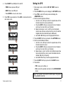
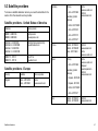
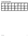
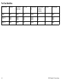
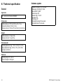
1
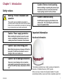
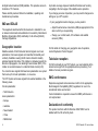
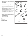
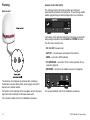
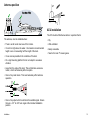
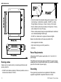
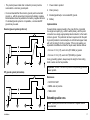
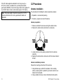
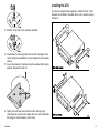
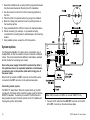
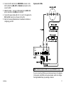
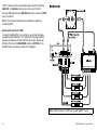
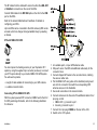
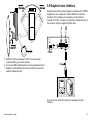
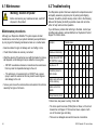
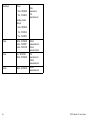
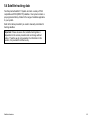
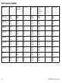
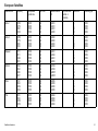
R a y m a r in e
3 3 S T V S a t e llit e
Te le v is io n S y s t e m
US Ve rs ion
Us e r’s Guide
Trademarks and registered trademarks
Autohelm, HSB, RayTech Navigator, Sail Pilot, SeaTalk and Sportpilot are UK registered trademarks of Raymarine UK Limited.
Pathfinder and Raymarine are UK registered trademarks of Raymarine Holdings Limited. 33STV, 45STV, 60STV, AST, Autoadapt, Auto
GST, AutoSeastate, AutoTrim, Bidata, G Series, HDFI, LifeTag, Marine Intelligence, Maxiview, On Board, Raychart, Raynav, Raypilot,
RayTalk, Raystar, ST40, ST60+, Seaclutter, Smart Route, Tridata, UniControl, Hybridtouch, and Waypoint Navigation are trademarks of
Raymarine UK Limited.
All other product names are trademarks or registered trademarks of their respective owners.
Copyright ©2009 Raymarine UK Ltd. All rights reserved.
ENGLISH
Document number: 81325-1
Date: 09-2009
Contents
Chapter 1 Introduction ............................................. 7
Safety notices................................................................. 7
Important information ...................................................... 7
5.2 Satellite coverage ..................................................... 46
5.3 Satellite providers ..................................................... 47
5.4 Satellite tracking data ................................................ 49
Chapter 2 Installation ............................................... 11
Chapter 6 Technical Specification .......................... 55
2.1 Preparation............................................................... 12
2.2 Procedures ............................................................... 18
6.1 Technical specification............................................... 56
Chapter 3 System operation & setup...................... 25
3.1 Introduction............................................................... 26
3.2 Getting started .......................................................... 26
3.3 Setup using the ACU................................................. 28
3.4 Applying factory default values................................... 37
3.5 System information ................................................... 37
3.6 Checking system power............................................. 38
3.7 Skew angle............................................................... 38
3.8 Graphical user interface............................................. 39
Chapter 4 Maintenance & troubleshooting ............ 41
4.1 Maintenance ............................................................. 42
4.2 Troubleshooting ........................................................ 42
4.3 Raymarine technical support...................................... 44
Chapter 5 Satellite information ............................... 45
5.1 Introduction............................................................... 46
5
6
33STV Satellite TV User’s Guide
Chapter 1: Introduction
Caution: Remove transit packing
Safety notices
Before installing or operating the product, open
the antenna unit cover and remove the foam
transit packing inserts from the unit base.
Warning: Product installation and
operation
This product must be installed and operated in
accordance with the Raymarine instructions provided.
Failure to do so could result in personal injury, damage
to your boat and/or poor product performance.
Caution: Power supply protection
When installing this product ensure the power
source is adequately protected by means of a
suitably-rated fuse or automatic circuit breaker.
Caution: Antenna coating
Do NOT paint or apply any other finish to the
antenna unit. This could degrade performance
beyond acceptable limits.
Important information
Handbook information
Caution: Use correct lifting point
When lifting the antenna unit, always lift from the
base plate. Do NOT use the antenna cover or
damage to the cover could occur.
Caution: Do not damage connectors
Take care to avoid damage to the connectors
underneath the antenna base plate when moving
the unit. Do NOT use these connectors to lift the
unit.
7
D11
40
-1
This handbook describes how to install, operate and maintain the
Raymarine 33 Satellite Television (33STV) system.
While out at sea or docked, the Raymarine Satellite TV system
automatically identifies, acquires and tracks compatible signals from
Introduction
7
all digital video broadcast (DVB) satellites. This provides access to
hundreds of TV channels.
Up to date coverage maps and satellite information are found by
navigating to the home page of the satellite service providers.
Please carefully read and follow the installation, operating and
maintenance procedures.
If you change your area of operation, you may need to change some
settings on your STV system:
IMO and SOLAS
The equipment described within this document is intended for use
on leisure marine boats and workboats not covered by International
Maritime Organization (IMO) and Safety of Life at Sea (SOLAS)
Carriage Regulations.
Geographic location
Satellites outside of North America transmit signals on a linear
polarization, this means signals are transmitted horizontally and
vertically. Satellites covering North America transmit circularly
polarized signals that rotate. If the rotation is clockwise towards the
direction of propagation, it is called right-hand-circular (RHC). If the
rotation is counterclockwise, it is called left-hand-circular (LHC).
You cannot receive signals that have linear polarization on a system
that is set up for circular polarization, or vice-versa.
The STV System will receive signals from selected satellites in the
following areas.
Circular polarization:
• North America
Linear polarization:
• If your geographic location changes, you may need to:
– Adjust the antenna low noise block (LNB) as appropriate for the
area in which you are operating.
– Change your control board, ACU software and satellite
receivers (IRDs).
For full details of changing your geographic area of operation,
contact Raymarine Product Support.
Television reception
For full functionality of your STV System, you must subscribe to the
relevant service(s) from the appropriate service provider(s). Full
details of service providers are given.
EMC conformance
Raymarine equipment and accessories conform to the appropriate
Electromagnetic Compatibility (EMC) regulations for use in the
recreational marine environment.
Correct installation is required to ensure that EMC performance is
not compromised.
• Europe
• Australia
Declaration of conformity
• New Zealand
This product conforms with EU Directive 2004/108/EC and is
labelled with the CE conformity mark.
• China
• Middle East
8
33STV Satellite TV User’s Guide
Product disposal
Dispose of this product in accordance with the WEEE Directive.
The Waste Electrical and Electronic Equipment (WEEE)
Directive requires the recycling of waste electrical and electronic
equipment. Whilst the WEEE Directive does not apply to some
Raymarine products, we support its policy and ask you to be aware
of how to dispose of this product.
Warranty registration
To register your Raymarine product ownership, please take a few
minutes to fill out the warranty registration card found in the box, or
visit www.raymarine.com and register on-line.
It is important that you register your product to receive full warranty
benefits. Your unit package includes a bar code label indicating the
serial number of the unit. You should stick this label to the warranty
registration card.
Technical accuracy
To the best of our knowledge, the information in this document was
correct at the time it was produced. However, Raymarine cannot
accept liability for any inaccuracies or omissions it may contain. In
addition, our policy of continuous product improvement may change
specifications without notice. As a result, Raymarine cannot accept
liability for any differences between the product and this document.
Introduction
9
10
33STV Satellite TV User’s Guide
Chapter 2: Installation
Chapter contents
•
2.1 Preparation on page 12
•
2.2 Procedures on page 18
Installation
11
2.1 Preparation
EMC installation guidelines
Raymarine equipment and accessories conform to the appropriate
Electromagnetic Compatibility (EMC) regulations, to minimize
electromagnetic interference between equipment and minimize the
effect such interference could have on the performance of your
system
Note: Where constraints on the installation prevent any of
the above recommendations, always ensure the maximum
possible separation between different items of electrical
equipment, to provide the best conditions for EMC performance
throughout the installation
Suppression ferrites
Correct installation is required to ensure that EMC performance is
not compromised.
Raymarine cables may be fitted with suppression ferrites. These
are important for correct EMC performance. If a ferrite has to be
removed for any purpose (e.g. installation or maintenance), it must
be replaced in the original position before the product is used.
For optimum EMC performance we recommend that wherever
possible:
Use only ferrites of the correct type, supplied by Raymarine
authorized dealers.
• Raymarine equipment and cables connected to it are:
– At least 1 m (3 ft) from any equipment transmitting or cables
carrying radio signals e.g. VHF radios, cables and antennas.
In the case of SSB radios, the distance should be increased
to 7 ft (2 m).
– More than 2 m (7 ft) from the path of a radar beam. A radar
beam can normally be assumed to spread 20 degrees above
and below the radiating element.
Connections to other equipment
Requirement for ferrites on non-Raymarine cables
If your Raymarine equipment is to be connected to other equipment
using a cable not supplied by Raymarine, a suppression ferrite
MUST always be attached to the cable near the Raymarine unit.
Parts supplied
The following parts are provided for a 33STV system:
• The product is supplied from a separate battery from that used
for engine start. This is important to prevent erratic behavior
and data loss which can occur if the engine start does not have
a separate battery.
• Antenna Unit
• Raymarine specified cables are used.
• Installation Kit comprising:
• Cables are not cut or extended, unless doing so is detailed in
the installation manual.
• Antenna Control Unit (ACU)
– Bolts
– Flat washers
– Spring washers
– Self tapping screws
• Cables as follows:
12
33STV Satellite TV User’s Guide
– R08321 - 10 m Power cable - used for connecting the ACU to
the DC power supply.
– R08257 - 3 m RF cable - used for connecting the ACU and
Integrated Receiver Decoder (IRD)
Power drill
– R08135 - 15 m RF cable - used for connecting the Antenna
and ACU.
5 mm
Allen key
50 mm (2 in)
hole saw
– R42173 - 1.5 m USB AB Type PC cable- used for connecting
the ACU to a PC for system setup and diagnostic.
– R42174 - 1.8 m USB AM to AM Type cable- used for connecting
the ACU to IRD (Only compatible with DIRECTV receiver).
10 mm (3/8 in)
spanner
11 mm (7/16 in)
spanner
8 mm (5/16 in)
drill
• CDROM - contains:
– Software for running the STV Graphical User Interface (GUI)
on a personal computer (PC).
Socket wrench
– Product user manual, as PDF.
Cross-head
screwdriver
Pencil
Tools required
Tools necessary for installation.
11 mm (7/16 in)
socket
Adhesive tape
D11735-1
Installation
13
Planning
Antenna Control Unit (ACU)
The Antenna Control Unit (ACU) provides all control and
power-switching functions for the antenna. Three soft keys enable
satellite programming and antenna diagnostics to be carried out.
Antenna unit
D11
73
D11531-1
Ante nna Unit
Two buttons at the right-hand side of the front panel are used with
some setup procedures to provide BACK and ENTER functions.
6 -1
The ACU rear connectors are:
• DC 9 to 30V for power input.
• ANT RF1 - connects power and signal to the antenna.
RF 1
RF 2
• NMEA - connects to GPS (optional).
• PC INTERFACE - connects to PC for remote operation from a
computer (optional).
• RECEIVER - connects to the satellite receiver (not supplied).
Ba s e pla te
conne ctor de ta il
MADE IN KOREA
Connectors on the underside of the base plate connect the power,
signal and control cabling from the below decks units.
-
ANT RF1
RECEIVER
+
-
+
DC 9 to 30V
FUSE
NMEA
RECEIVER USB PORT
PC INTERFACE
D11728-2
The Antenna unit comprises the antenna dish, positioning
mechanism, low noise block (LNB), power supply and control
elements in a molded radome.
For connection details, refer to the installation procedures.
For connection details, refer to the installation procedures.
14
33STV Satellite TV User’s Guide
Antenna position
90 0
Clear view of sky
+15
0
Blocked!
D7951_1
Mast
ACU installation
D11449-1
The ACU must be fitted below decks in a position that is:
The antenna, must be installed where:
• Dry.
• There is an all round clear view of the horizon.
• Well ventilated.
• It is not too high above the water - the maximum recommended
height is one not exceeding half the length of the boat.
• Easily accessible.
• Near to the main TV viewing area.
• It is as near as possible to the centerline of the boat.
• On a rigid mounting platform that is not subject to excessive
vibration.
• Away from the edge of the boat. This will minimize excessive
motion, which can adversely affect reception.
• Clear of any radar beam. This could adversely affect antenna
operation.
Above the beam
Min 1.2 m (4 ft)
In the
beam
Min 1.2 m (4 ft)
Below the beam
D79
50_1
• Clear of any object which could block the satellite signal. Ensure
there is a +15° to +90° look angle at the intended installation
position.
Installation
15
ACU dimensions
Minimum bend
200 mm (8 in)
diameter
178 mm (7.0 in)
228 mm (9.0 in)
Minimum bend of cable
100 mm (4 in) radius
• Protect all cables from physical damage and exposure to heat.
Use trunking or conduit where possible. Do NOT run cables
through bilges or doorways, or close to moving or hot objects.
• Secure cables in place using tie-wraps or lacing twine. Coil any
extra cable and tie it out of the way.
• Where a cable passes through an exposed bulkhead or deckhead,
use a suitable watertight feed-through.
• Do NOT run cables near to engines or fluorescent lights.
Always route data cables as far away as possible from:
185 mm (7.3 in)
• other equipment and cables,
55 mm
(2.2 in)
• high current carrying ac and dc power lines,
• antennae.
Power Requirements
217 mm (8.5 in)
D11550-1
Routing cables
Cables must be routed correctly, to maximize performance and
prolong cable life.
• Do NOT bend cables excessively. Wherever possible, ensure a
minimum bend radius of 100 mm.
16
A Raymarine 33STV system needs either a 12 V dc or 24 V dc
power supply.
If the IRD(s) and television(s) require a 220/240 V ac power supply,
a suitable dc-to-ac converter must be fitted, to provide the necessary
power from the boat’s dc power supply.
Grounding
These grounding requirements are applicable for Raymarine
equipment supplied with a separate drain wire or screen.
33STV Satellite TV User’s Guide
• The product power cable drain conductor (screen) must be
connected to a common ground point.
1. Power cable to product
2. Drain (screen)
• It is recommended that the common ground point is a bonded
ground, i.e. with the ground point connected to battery negative,
and situated as close as possible to the battery negative terminal.
If a bonded ground system is not possible, a non-bonded RF
ground may be used.
3. Bonded (preferred) or non-bonded RF ground.
4. Battery
Implementation
If several items require grounding, they may first be connected
to a single local point (e.g. within a switch panel), with this point
connected via a single, appropriately-rated conductor, to the boat’s
common ground. The preferred minimum requirement for the path
to ground (bonded or non-bonded) is via a flat tinned copper braid,
with a 30 A rating (1/4 inch) or greater. If this is not possible, an
equivalent stranded wire conductor maybe used, rated as follows:
Bonded ground system (preferred)
• for runs of <1 m (3 ft), use 6 mm2 (#10 AWG) or greater.
1
2
3
4
D11709-1
• for runs of >1 m (3 ft), use 8 mm2 (#8 AWG) or greater.
RF ground system (alternative)
In any grounding system, always keep the length of connecting
braid or wires as short as possible.
Important: Do NOT connect this product to a positively-grounded
power system.
References
• ISO10133/13297
• BMEA code of practice
• NMEA 0400
1
Installation
2
3
4
D11710-1
Extending cable runs
Note: System performance will be reduced if supplied cables
are extended.
17
If the RF cable supplied as standard is not long enough, a
98 ft (30 m) cable, is available from your Raymarine dealer,
(part number E96008). Connect the longer cable to the supplied 15
m (49 ft) RF cable to obtain a total cable length of 147 ft (45 m).
Note: Total cable lengths should not exceed 45 m (147 ft).
System performance can not be guaranteed if cables are
extended.
2.2 Procedures
Antenna installation
The procedures for installing the antenna assembly comprise:
• Preparation - remove transit packing.
• Procedure - prepare mount and fit antenna.
Antenna preparation
1. Remove and retain the screws securing the antenna dome.
2. Remove the antenna dome and retain in a safe place.
Packing
restraint
Packing
restraint
D11564_1
3. Locate and remove the packing restraints from the antenna
assembly.
4. Replace the antenna dome and secure with the screws retained
at step 1.
Antenna installation procedure
Prepare the mounting surface then fit the antenna.
1. Using adhesive tape, attach the template to the mounting
surface, ensuring that it is parallel to your boat’s center line as
marked on the template.
2. Using a suitable hole saw, remove the shaded center portion.
18
33STV Satellite TV User’s Guide
Installing the ACU
ni
U
e
as
B e
a plat
nn
e m
nt Te
A
Use the two fixing brackets supplied to install the ACU. These
brackets can be fitted to the sides of the unit to provide a top or
bottom fix.
t
inc
mm
.3
114
)
hes
inc
mm
1 /2
(4
(4 1
/2
)
)
hes
inc
.3
114
hes
dia
, 3 /20
(3
t hole
Cu mm er
80 met
4
h)
inc
e, 10
4/
llhol ( in
Dri mm er ns
10 met itio
dia pos
.6
228
mm
(9
es)
.6
228
mm
(9
inch
es)
inch
D11451-1
3. Drill four 8 mm holes in the positions indicated.
ni
U
e
as
B e
a plat
nn
e m
nt Te
A
t
dia
, 3 /20
(3
t hole
Cu mm er
80 met
4
h)
inc
e, 10
4/
llhol ( in
Dri mm er ns
10 met itio
dia pos
mm
.3
114
hes
inc
mm
1 /2
(4
(4 1
/2
hes
inc
)
)
hes
inc
.3
114
)
.6
228
mm
(9
228
.6
mm
(9
inch
es)
es)
inch
D11452-1
4. Countersink the mounting holes, then smooth the edges of the
center hole with a suitable file, to avoid damage to the mounting
surface.
5. Secure the antenna to the base using the supplied bolts, spring
washers, flat washers and nut.
Ant
enna
Con
rtol
Uni
t
Under shelf mounting
-1
31
17
D1
Ant
enna
Con
rtol
Uni
t
6. Tighten the bolts and ensure that the foam sealing ring is
compressed to prevent water ingress. Be sure not to overtighten
the fixings or cross-thread any of the bolts.
Installation
Desk top mounting
D11551-1
19
Antenna base plate
1. Select the installation site, ensuring that the proposed site meets
the criteria described under Planning the ACU installation.
2. Use the screws from the ACU to fix the mounting brackets to
the ACU.
3. Place the ACU in the position where it is going to be installed.
4. Mark the 2 fixing hole positions for each mounting bracket, on
the mounting surface.
5. Using a suitable drill bit, drill the 4 holes in the marked positions.
6. Where necessary (for example, on gel-coated surfaces),
countersink the mounting holes to avoid damage to the mounting
surface.
7. Using suitable screws, secure the ACU into position.
RF 1
IRD (not supplied)
MADE IN KOREA
ANT RF1
Connecting a basic system
For DIRECTV subscribers: When the system starts up, the IRD
can take 20~30 minutes to fully load the program guide for all three
DIRECTV satellites. To enable you to watch TV whilst the list is
being loaded only select channels carried on the 101 satellite until
the program guide is fully loaded.
20
RECEIVER
+
+
DC 9 to30V
FUSE
NMEA
-
RECEIVER USB PORT
PC INTERFACE
PC cable
NMEAGPS
USB cable
Ensure the power supply for the ACU is protected by either a
5 A quick-blow fuse or an equivalent automatic circuit breaker,
connected in-line on the positive (white with red tag) wire of
the power cable.
Note that for all variants, the RF1 connector on the ACU must be
connected to the RF1 connector on the antenna base plate.
connects to
Television Monitor
(not supplied)
ACU
-
Your Raymarine Satellite TV system can be connected to one or
multiple IRDs, to offer the maximum choice of channels to different
cabins. This section describes the different combinations available
and the method of connecting each variant.
RF 2
D11727-3
System options
RF cable
Brown with
red sleeve
Blue with
blue sleeve
12 V or 24 V dc
power supply
Green/yellow with
white sleeve
Drain (screen)
Ground
Note: USB Connection to IRD is for use with DIRECTV only.
1. Connect an RF cable from the ANT RF1 connector on the ACU
to the RF1 connector on the antenna base plate.
33STV Satellite TV User’s Guide
2. Connect an RF cable from the RECEIVER connector on the
ACU to either the LNB, ANT, or Satellite In connector on the
rear of the IRD.
3. DIRECTV ONLY— Connect a USB cable from the IRD1 USB
port on the ACU to the USB port on the IRD.
4. Connect the power cable with a 12 V or a 24 V dc supply to the
DC 9 to 30 V connector on the rear of the ACU.
5. Refer to the relevant Manufacturer’s handbook for details on
configuring your IRD.
System with 2 IRDs
Antenna base plate
RF 1
RF 2
IRD2 (not supplied)
RF cable
to TV monitor (not supplied)
IRD1 (not supplied)
to TV monitor (not supplied)
ACU
MADE IN KOREA
ANT RF1
RECEIVER
+
+
FUSE
DC 9 to 30V
NMEA
-
RECEIVER USB PORT
PC INTERFACE
D11729-2
-
Power in
PC cable
NMEAGPS
USB cable
Note: USB Connection to IRD is for use with DIRECTV only.
You can connect two IRDs to your antenna as shown in the diagram.
In this system, both IRDs can be set as master, which can change
the target satellite freely by selecting a channel.
Installation
21
The RF cables from the antenna base plate connect to either the
LNB, ANT, or Satellite In connector on the rear of the IRD.
N o r t h Am e r ic a
Antenna base plate
Connect USB cables from an IRD USB port on the ACU to the USB
port on the IRDs.
RF 1
RF 2
Refer to the relevant manufacturer’s handbook for details on
configuring IRDs.
System with more than 2 IRDs
* Must be connected
to LHCP/ 18V
To connect multiple IRDs to your antenna, you should purchase
a suitable active multiswitch. The multiswitch should be installed
between the antenna unit and the IRDs (as shown). Ensure the
RF cable from the ACUs RECEIVER and the LHCP/18V on the
multiswitch are connected as shown in the diagram.
ACU
MADE IN KOREA
ANT RF1
RECEIVER
+
+
DC 9 to 30V
FUSE
NMEA
-
RECEIVER USB PORT
PC INTERFACE
D11730-2
-
LNB
RHCP/+13V
VHF/UHF
INPUT
Power in
OUT 1
OUT 2
OUT 3
OUT 4
OUT 5
IRD1 (not supplied)
IRD2 (not supplied)
IRD3 (not supplied)
USB cable
IRD4 (not supplied)
Note: USB Connection to IRD is for use with DIRECTV only.
22
LNB
LHCP/ +18V
Multiswitch
P C ca ble
NMEAGPS
POWER
24V DC
33STV Satellite TV User’s Guide
OUT 6
The RF cables from the multiswitch connect to either the LNB, ANT,
or Satellite In connectors on the rear of the IRDs.
Connect USB cables to the IRD USB ports on the ACU to the USB
port on the IRDs.
GPS antenna
cable
Red (12 - 32 V /+)
Refer to the relevant Manufacturer’s handbook for details on
configuring your IRDs.
Up to six IRDs can be connected to the ACU and every IRD can be
a master, which can change the target satellite freely by selecting
a channel.
Yellow (NMEAout /+)
Connector
block
Brown (RTCMin /+)
Green (NMEAin /+)
Shield (0V/ ground / -)
STV with NMEA 0183 GPS
Pin 1
GPS antenna
cable
17
D1
_
26
17
D1
1
NMEA
connector
You can improve the tracking accuracy of your Raymarine STV
system by using the supplied 2 pin connector (as above), to connect
your STV system directly to your boat’s NMEA 0183 GPS system.
You will need to provide:
• a length of cable suitable for connecting to your GPS antenna.
• a suitable connector block.
Connecting STV to NMEA 0183 GPS
With the system powered OFF, connect an NMEA feed to the ACU
for GPS positioning information, refer to the following illustration
for reference:
Installation
25
_1
Pin 2
Additional cable
1. At a suitable point, cut your GPS antenna cable.
2. Strip each wire in the GPS and additional cable ready for the
connector block.
3. Connect stripped GPS wires to the connector block, matching
the wires on either side.
4. Put the NMEA OUT wire (yellow in the illustration) and ground
wire into the connector block with the corresponding GPS
antenna wires, as in the illustration.
5. Secure all connections in the connector block.
6. Connect and secure the free end of the additional cable in the 2
pin plug, so that:
i. NMEA OUT (+) connects to pin 1.
ii. Ground (-) connects to pin 2.
7. Connect the 2 pin plug to NMEA on the rear of the ACU.
8. Switch on the STV system.
23
24
33STV Satellite TV User’s Guide
Chapter 3: System operation & setup
Chapter contents
•
3.1 Introduction on page 26
•
3.2 Getting started on page 26
•
3.3 Setup using the ACU on page 28
•
3.4 Applying factory default values on page 37
•
3.5 System information on page 37
•
3.6 Checking system power on page 38
•
3.7 Skew angle on page 38
•
3.8 Graphical user interface on page 39
System operation & setup
25
3.1 Introduction
3.2 Getting started
This section of the handbook describes how to set up your
Raymarine Satellite TV system after installation using the ACU or the
Graphical User Interface (GUI), and includes the following functions:
Switching on
• System start up
• Setting the GPS
• Change the default satellite
• Editing satellite information
• Monitor the antenna status
• Setting antenna parameters
• Setting sleep mode
• Setting the local frequency
• Enter set up mode
• Setting the DiSEqC method
• Setting your operating region
• Display versions
• Setting the default satellites
• Setting antenna go position
• Setting up Remote Control
• Setting antenna move step
Ensure your IRDs and television monitors are switched on.
Press the power switch on the ACU to switch on the system. Check
on the ACU that the start-up screens are displayed in the correct
sequence.
Many of the above functions will only be required at initial installation
of your system.
Important: Raymarine does not recommend changing the
satellite information unless advised to do so by the satellite
provider.
Note: The satellite names shown on the ACU screen are
dependent on geographic location and therefore may be different
to the names in this manual.
Note: Vertical and horizontal polarization applies to regions with
linear polarization only.
26
33STV Satellite TV User’s Guide
Startup sequence
S ta rt of communica tion be twe e n a nte nna a nd the ACU.
I NI T I AL I Z E ACU
RAYMARI NE 3 3 S TV
name of the satellite the system is currently tracking is shown in
the top line of the ACU display.
TRACKI NG A:
B: HOT BI RD
AS T RA2
S E TUP
T RACKI NG A: HOT BI RD
B: AS TRA2
S ET UP
Ante nna initia lize d.
I NI T I ALI Z E ANTE NNA
RAYMARI NE 3 3 S TV
System with 2 default satellites
Ante nna is s e a rching for S a te llite A.
AS TRA2
S ET UP
TRACKI NG A: AS T RA2
B: HOT BI RD TURKS AT
T RACKI NG B: HOTBI RD
T URKS AT
AS T RA2
D11561-2
S EARCH A:
HOT BI RD
Ope ra ting mode - a nte nna tra cking s a te llite
TRACKI NG A:
B: HOTBI RD
AS TRA2
S ET UP
S ys te m s e t with two
de fa ult s a te llite s
TRACKI NG A: AS TRA2
B: HOTBI RD T URKS AT
System with 3 default satellites
S ys te m s e t with thre e
de fa ult s a te llite s
To change the default satellite, press the left hand soft key. The
D11737-1
Changing the target satellite
Your satellite system can be set up to track either two or three
default satellites, depending on your geographical location. The
System operation & setup
T RACKI NG C: TURKS AT
HOTBI RD
AS TRA2
default satellite changes and is automatically tracked by the
antenna.
Monitoring antenna operation
With the system switched on and running, the ACU display shows
the current status of the antenna. This can be either:
27
• TRACKING - the antenna is tracking the satellite
• SEARCH - the antenna is looking for the satellite
• UNWRAPPING - the antenna is unwrapping cable
You can check the details of the satellite position by pressing the
center soft key:
• Once to see the elevation
• Twice to see latitude, longitude and signal strength
• Three times to return to the normal operating display
Setting sleep mode
If the antenna looses the tracking satellite whilst in sleep mode,
sleep mode is cancelled. To register a key on your remote control to
access sleep mode see ’Setting the remote control’.
1. Press Back to access sleep mode.
2. Press Back again to exit sleep mode.
3.3 Setup using the ACU
Setup principles
Using the ACU
The ACU setup mode gives access to a series of setup pages, to
enable you to adjust the system parameters.
When setting up the system from the ACU, three context-dependent
soft keys below the display are used to select and adjust the
required parameters.
SET SAT PAIR?
PREV
YES
NEXT
BACK soft key
ENTER soft key
Context-dependent soft keys
Single function soft keys are used only during setup routines:
• The BACK soft key enables you go to the previous screen.
T RACKI NG A:
B: HOTBI RD
AS TRA2
S ET UP
• The ENTER soft key is used to confirm settings.
You can:
• Define a pair or trio of satellites you want to use.
• Set the system to work with GPS.
AS TRA2
S ET UP
• Edit a range of satellite information.
D11738-2
T RACKI NG A:
B: HOT BI RD
• Set various antenna parameters.
• Set the LNB local frequency.
• Set the DiSEqC method.
• Reset the system to factory default values.
You can also use setup mode to manually control the direction that
the antenna points.
28
33STV Satellite TV User’s Guide
Setup routines
1. Press the ENTER soft key to display the setup entry page.
Editing screens
Some setup screens enable you to edit individual characters and
are typically presented in this manner:
SAT NAME: ASTR
INPUT
A2
+
BACK
ENTER
NO
D11554-1
For some setup functions, you also use the PREV and NEXT soft
key to select a particular value. For example, when setting default
satellites, you use PREV or NEXT cycle through the names of
available satellites.
SETUP MODE?
YES
2. Press the YES soft key to display the SET SAT PAIR? screen.
This is the first screen in setup mode.
SET SAT PAIR?
PREV
YES
NEXT
D11556-1
In setup mode, use the PREV or NEXT soft key to select the
required setup screen.
Setting the operating region
On the screen, the editable character is indicated by an underscore
cursor (under A in this illustration).
To edit the characters:
1. With the cursor under the first character, use the - and/or + soft
keys to move through the available characters until the required
character is displayed above the cursor.
2. Press the INPUT soft key to accept the edited character. The
cursor then moves to the next character.
3. Repeat steps 1 and 2 until you have edited all necessary
characters. If you want to change any character, use the BACK
soft key to move the cursor to the relevant character.
4. When you have completed the edit for a screen, press the
ENTER soft key to accept the values and move to the next setup
screen.
Entering setup mode
Enter setup mode as follows:
System operation & setup
Use this procedure to set the region you are operating in.
1. Carry out the Enter setup mode procedure to display the SET
SAT PAIR? screen.
2. Press the PREV soft key twice to display the LOAD REGION
INFO? screen.
3. Press the YES soft key to display the CONTINENT select screen.
4. Use the PREV or NEXT soft key to cycle through the continent
names in the top line of the display, until the required continent
name is displayed.
5. Press the SELECT soft key to confirm the continent and display
the REGION screen.
6. Use the PREV or NEXT soft key to cycle through the region
names in the top line of the display, until the required region
name is displayed.
7. Press the SELECT soft key to confirm the region and display
the LOAD? screen.
8. Press either:
29
• YES to load the new settings. When the new settings have
been loaded, the system re-initializes automatically.
• NO to return to the SETUP MODE? screen without making
any changes.
9. If the SETUP MODE? screen is displayed, press:
• YES if you want to remain in setup mode, or
• NO to re-initialize the system and return to operational mode.
Setting the default satellites
Use this procedure to set either two or three default satellites.
1. Carry out the Enter setup mode procedure to display the SET
SAT PAIR? screen.
2. Press the YES soft key to display the SET TRIPLE SAT screen.
3. If you are in an area where three satellites are available press
YES. Otherwise, press NO.
4. Use the PREV or NEXT soft key to cycle through the satellite
names, in the top line of the display.
5. When the required satellite name is displayed, press the
SELECT soft key to select this satellite as satellite A.
6. Repeat steps 4 and 5 to select satellite B.
7. If you are setting up triple satellites, repeat steps 4 and 5 to
select satellite C.
8. When the SAVE? screen is displayed, press the YES soft key.
9. When the SETUP? screen is displayed, press either soft key:
• YES if you want to remain in setup mode, or
• NO to re-initialize the system and return to operational mode.
Setting the remote control
Use this procedure to set up your remote control with the ACU.
30
1. Carry out the enter setup mode procedure to display the SET
SAT PAIR? screen.
2. Press the NEXT soft key 8 times to display the SET REMOCON?
screen.
3. Press YES to display the CHANGE SAT set screen.
4. Press the SELECT soft key to display the PRESS A REMOTE
KEY screen.
5. Point your remote control towards the ACU, then press the
remote control button that you want to allocate to the selected
function.
6. Press the same remote control button again to confirm the
selection.
7. If you want to set up another remote function:
i. At the ACU, press the BACK soft key.
ii. Press the NEXT soft key to select the next function to set up.
iii. Repeat steps 4 to 7 above.
8. When all required functions have been set for remote control,
press the EXIT soft key to return to the main setup mode.
Setting MutiSat interface module (MIM)
Note:
MIM functions are only available when connected to a DIRECTV
receiever.
Up to six IRDs can be connected to the ACU. Every IRD can be a
master, which can change the target satellite freely by selecting
a channel.
Follow the steps below to enable/disable this function:
1. Press YES to enter setup mode.
2. Press NEXT eleven times to enter MIM mode
3. Press YES to set MIM
33STV Satellite TV User’s Guide
4. Press ON/OFF to set MIM port On and Off,
• PREV- Moves previous IRD port.
• NEXT- Moves next IRD port.
• Press ENTER to move to next screen.
5. Press YES to save selections. Press NO to cancel and return to
main setup mode.
S ET UP MODE?
YE S
NO
S ET S AT P AI R?
P RE V
YE S
NE XT
S ET MI M?
P RE V
MI M:
P RE V
YES
NEXT
1 2 3 4 5 6
ON/ OF F
NEXT
Setting the GPS
1. Enter setup mode, so that the SET SAT PAIR? screen is
displayed.
2. Press the NEXT soft key once to display the SET GPS? screen.
3. Press YES to enter GPS setup mode and display the
LONGITUDE screen.
4. Set the current longitude as follows:
i. Use the + and - soft keys to enter the required value for the
character above the cursor (underscore).
ii. Press the INPUT soft key to accept each correct character
and move the cursor to the next character.
iii. Repeat sub-steps a, b and c until the correct longitude
numeric value has been entered and the cursor is under the
longitude direction indicator, E (east) or W (west).
iv. Use the E or W soft key to set the appropriate direction.
5. Press the INPUT soft key to proceed to the LATITUDE screen.
6. Set the current latitude as follows:
i. Use the + and - soft keys to enter the required value for the
character above the cursor.
ii. Press the INPUT soft key to accept each correct character
and move the cursor to the next character.
iii. Repeat steps a, b and c until all correct latitude values have
been entered and the cursor is under the latitude direction
indicator, N (north) or S (south).
iv. Use the N or S soft key to set the appropriate direction
7. Press the INPUT soft key to proceed to the SAVE? screen.
8. Press either:
• YES to save your settings, or
S AVE?
NO
D11742-1
YE S
System operation & setup
• NO to cancel the operation and return to the SETUP MODE?
screen.
Note: If your system is connected to a GPS antenna, the position
will be updated in real time.
31
Satellite information
Important: We recommend that you do NOT attempt to edit
satellite information. However, if you have to do so, contact the
Raymarine Customer Support Department for advice before
making any changes.
The editable parameters are typically, in sequence:
– ONLY 13 V - always supply 13 V to LNB.
– ONLY 18 V - always supply 18 V to LNB.
• The required method of Digital Satellite Equipment Control
(DiSEqC). The options are:
– AUTO - change signal to LNB by the IRD DiSEqC. This is the
RECOMMENDED SETTING.
• LONGITUDE in degrees and minutes, plus E/W selector.
– ONLY 0 KHZ - always supply 0 kHz to LNB.
• VER LOW/RHCP. Vertical low band tracking frequency (in MHz)
and symbol rate (in kHz).
– ONLY 22KHZ - always supply 22 kHz to LNB.
• VER LOW NID. Vertical low band network identity (NID).
• HOR LOW/LHCP. Horizontal low band tracking frequency (in
MHz) and symbol rate (in kHz).
• HOR LOW NID. Horizontal low band network identity (NID).
• VER HIGH. Vertical high band tracking frequency (in MHz) and
symbol rate (in kHz).
• VER HIGH NID. Vertical high band network identity (NID).
• HOR HIGH. Horizontal high band tracking frequency (in MHz)
and symbol rate (in kHz).
• HOR HIGH NID. Horizontal high band network identity (NID).
• The method of verifying satellite tracking. The options are:
– SIGNAL - use only the signal level for tracking.
– DVB LOCK - use only DVB Lock signal for tracking.
– DVB DECODE - verify signal using DVB decoding method for
tracking.
– DSS DECODE - decode only DSS Lock signal for tracking.
• The method of supplying power to the LNB. The options are:
– AUTO - change voltage to LNB by the IRD voltage. This is the
RECOMMENDED SETTING.
32
Editing satellite information
To edit satellite information, start with normal operating information
displayed on the ACU, then at the ACU:
1. Carry out the Enter setup mode procedure to display the SET
SAT PAIR? screen.
2. Press the NEXT soft key twice to display the EDIT SAT INFO?
screen.
3. Press YES to enter the edit mode.
A satellite name edit screen is displayed.
4. Use the PREV or NEXT soft key to scroll to the name of the
satellite you want to change.
5. To edit the displayed satellite name, press the SELECT soft key.
An edit screen is displayed.
6. Change the displayed name as follows:
i. Use the + and - soft keys to change the value of the character
above the cursor (underscore).
ii. Press the INPUT soft key to accept each correct character
and move the cursor to the next character.
iii. Repeat sub-steps a, b and c until the correct name has been
entered.
7. Press the ENTER soft key to confirm the edited data and display
the edit screen for the next parameter.
33STV Satellite TV User’s Guide
8. Using a procedure similar to that in steps 2 to 7 above, edit the
other satellite parameters as required. The editable parameters
are typically, in sequence:
• LONGITUDE
• VER LOW/RHCP
• The YES soft key to save the changes you have made, or
• The NO soft key to discard any changes.
The SETUP MODE? entry screen is then displayed.
16. Press either:
• VER LOW NID.
• the YES soft key, if you want to use another setup function, or
• HOR LOW/LHCP
• the NO soft key, to re-initialize the system using the new
settings.
• HOR LOW NID
• VER HIGH
Antenna parameters
• VER HIGH NID
• HOR HIGH
• HOR HIGH NID
Press the ENTER button to accept the HOR HIGH NID value,
and display the VERIFY screen.
9. If necessary, use the PREV or NEXT soft key to select the
required method for verifying satellite tracking.
10. Press the ENTER button to accept the VERIFY method and
display the VOLTAGE screen.
11. If necessary, use the PREV or NEXT soft key to select the
required method of supplying power to the LNB.
12. Press the ENTER button to accept the VOLTAGE method and
display the DISEQC screen.
13. If necessary, use the PREV or NEXT soft key to select the
required method of Digital Satellite Equipment Control (DiSEqC).
The options are:
i. AUTO
ii. 0KHz
iii. 22KHz
14. Press the ENTER soft key to accept the DISEQC method and
display the SAVE? screen.
15. Press, either:
System operation & setup
Important: We recommend that you do NOT attempt to change
the antenna parameters. However, if you have to do so, contact
the Raymarine Customer Support Department for advice before
making any changes.
The antenna parameters you can change are typically, in sequence:
• SCAN OFFSET. The angle between the marked point on the
sub-reflector and the datum.
• TRACK SCALE. To determine the speed at which the antenna
tracks a satellite. A high Track Scale value gives a high tracking
speed.
• DETECT LEVEL. The basic signal detection level.
• WRS LEVEL. The basic WRS detection level.
• TRACK OFFSET.
• POWER LEVEL.
• DISEQC LEVEL. The value that identifies a 22 kHz tone.
• OFFSET RH - LH. The difference value between RHCP/LHCP
and SCAN OFFSET.
• EL OFFSET.
33
• USE WRS. Applies WRS while antenna is searching for satellite.
• OFFSET DIFF. Applies Offset Difference.
Editing antenna parameters
1. Carry out the Enter setup mode procedure to display the SET
SAT PAIR? screen.
2. Press the NEXT soft key three times to display the SET ANT
PARAMETER? screen.
3. Press YES to enter parameter edit. The PARAM: SCAN
OFFSET: screen is displayed.
4. Use the PREV and NEXT soft keys as necessary, to display the
parameter you want to change.
5. To change the displayed parameter, press the YES soft key.
An edit screen is displayed.
6. Change the displayed parameter as follows:
i. Use the + and - soft keys to change the value of the character
above the cursor (underscore).
ii. Press the INPUT soft key to accept each correct character
and move the cursor to the next character.
iii. Repeat sub-steps a, b and c until the correct name has been
entered.
7. Press the ENTER soft key, to display the ANOTHER
PARAMETER? screen.
8. To:
The SETUP MODE? entry screen is then displayed.
10. Press either:
• the YES soft key, if you want to use another setup function, or
• the NO soft key, to re-initialize the system using the new
settings.
Setting LNB local frequency
We recommend that you do NOT attempt to change the LNB local
frequency.
However, if you have to do so, contact the Raymarine Customer
Support Department for advice before making any changes.
1. Carry out the Enter setup mode procedure to display the SET
SAT PAIR? screen.
2. Press the NEXT soft key four times to display the SET LOCAL
FREQ? screen.
3. Press YES to display the LNB TYPE: screen.
4. Carry out the setting up procedure for single band or universal
band, as necessary.
• Single band frequencies are:
– Asia, 11300 Mhz.
• Exit the setup procedure, press the NO soft key to display
the SAVE? screen.
– Japan, 10678 MHz
• Set up another antenna parameter, press the YES soft key to
return to the parameter change routine, then repeat steps 4
to 8 as necessary.
– America. 11250 MHz
9. When the SAVE? screen is displayed, press, either:
• The YES soft key to save the changes you have made, or
34
• The NO soft key to discard any changes.
– Korea, 10750 MHz
• Universal frequencies are:
– Low band, 9750 MHz
– High band, 10600 MHz
33STV Satellite TV User’s Guide
Setting single band LNB frequency
• YES if you want to use another setup function, or
With the LNB TYPE: screen displayed:
• NO to re-initialize the system using the new settings.
1. Use the PREV or NEXT soft key to scroll to SINGLE
2. Press SELECT to display the LOCAL FREQ edit screen
3. Set the required frequency as follows:
i. Use the + and - soft keys to change the value of the character
above the cursor (underscore), as necessary.
ii. Press the INPUT soft key to accept each correct character
and move the cursor to the next character.
iii. Repeat sub-steps a, b and c until the correct frequency has
been entered.
4. Press the ENTER button to accept the frequency value and
display the SAVE? screen.
5. Press, either:
• The YES soft key to save the changes you have made, or
• The NO soft key to discard any changes.
The SETUP MODE? entry screen is then displayed.
6. Press either:
• YES if you want to use another setup function, or
• NO to re-initialize the system using the new settings.
Setting universal LNB frequency
With the LNB TYPE: screen displayed:
1. Use the PREV or NEXT soft key to scroll to UNIVERSAL
2. Press, either:
• The YES soft key to save the changes you have made, or
• The NO soft key to discard any changes.
The SETUP MODE? entry screen is then displayed.
3. Press either:
System operation & setup
Setting the DiSEqC method
We recommend that you do NOT attempt to change the DiSEqC.
However, if you have to do so, contact the Raymarine Customer
Support Department for advice before making any changes.
1. Carry out the Enter setup mode procedure to display the SET
SAT PAIR? screen.
2. Press the NEXT soft key five times to display the USE DISEQC?
screen.
3. Press YES to display the DiSEqC edit screen.
4. Use the PREV or NEXT soft keys to select the required DiSEqC
method. The options are:
• USE TO CHANGE BAND - DiSEqC used to change high and
low bands.
• USE TO CHANGE SAT - DiSEqC used to change the satellite
being tracked.
• DO NOT USE DISEQC - DiSEqC not used.
5. Press the ENTER soft key to accept the frequency value and
display the SAVE? screen.
6. Press, either:
• The YES soft key to save the changes you have made, or
• The NO soft key to discard any changes.
The SETUP MODE? entry screen is then displayed.
7. Press either:
• YES if you want to use another setup function, or
• NO to re-initialize the system using the new settings.
35
Manually directing the antenna
You can use the ACU to manually control the antenna. The options
are:
• Setting the antenna go position - you set horizontal and vertical
angles to which you want the antenna to point.
• Antenna move step - enables you to manually step the antenna,
to the required horizontal and vertical directions.
Setting antenna go position
1. Carry out the Enter setup mode procedure to display the SET
SAT PAIR? screen.
2. Press the PREV soft key five times to display the ANT GO
POSITION? screen.
3. Press YES to display the GO TO AZ edit screen.
4. Define the horizontal position to which you want the antenna to
move, as follows:
i. Use the + and - soft keys to change the value of the character
above the cursor (underscore).
ii. Press the INPUT soft key to accept each correct character
and move the cursor to the next character.
iii. Repeat sub-steps a, b and c until the required value has
been entered.
5. Press the ENTER soft key to confirm the horizontal position and
display the GO TO EL edit screen.
6. Using a procedure similar to that in steps 4 and 5, define the
vertical position to which you want the antenna to move.
7. Press the ENTER soft key to confirm the vertical position and
display the GOTO POSITION? screen.
8. Press:
• NO to return to the ANT GO POSITION? screen.
Setting antenna move step
1. Carry out the Enter setup mode procedure to display the SET
SAT PAIR? screen.
2. Press the PREV soft key four times to display the ANT MOVE
STEP? screen.
3. Press YES to display the STEP AZ control screen.
4. Use the CCW or CW soft keys to step the antenna
counter-clockwise or clockwise, to the required horizontal
direction. The horizontal angle is displayed on the top line.
5. When you have set the required horizontal direction, press the
EL soft key to display the STEP EL control screen.
6. Use the DOWN or UP soft keys to step the antenna, to the
required horizontal direction. The vertical angle is displayed on
the top line.
7. To leave the antenna move step mode, press the EXIT soft key
to return to the ANT MOVE STEP? screen.
• YES to drive the antenna to the position you have set. When
you no longer need the antenna to point in this direction, press
the EXIT soft key to return to the SETUP MODE? screen.
36
33STV Satellite TV User’s Guide
3.4 Applying factory default values
3.5 System information
If you want to return all settings to the factory default values, use
the following procedure:
You can use the ACU to display system product serial numbers and
software versions.
1. Carry out the Enter setup mode procedure to display the SET
SAT PAIR? screen.
2. Press the PREV soft key once to display the SET DEFAULT?
screen.
3. Press YES.
The procedure for doing this is described as part of the maintenance
procedures.
The message DEFAULT SETTING is displayed and the
parameter values are reset. When the procedure is complete,
the SETUP MODE? entry screen is displayed.
4. Press either:
• YES if you want to change the setup values, or
• NO to re-initialize the system using the default settings.
System operation & setup
37
3.6 Checking system power
3.7 Skew angle
1. Carry out the Enter setup mode procedure to display the SET
SAT PAIR? screen.
2. Press the NEXT soft key seven times to display the VIEW
POWER? screen. The following information is displayed:
If you need to improve your satellite signal reception, you may be
able to do so by adjusting the skew angle. Before attempting to do
this, seek advice from your service provider.
The following information is displayed sequentially:
• ACU POWER
• ANT POWER (antenna power)
• IRD power.
3. To leave the power display, press the EXIT soft key.
The SETUP MODE? entry screen is then displayed.
4. Press either:
• YES if you want to use another setup function, or
• NO to re-initialize the system.
Note: Before attempting to adjust the skew angle ensure all
power to the STV system is switched off. DO NOT attempt to set
the skew angle with power applied.
Setting the skew angle
Contact your service provider to obtain the optimum skew angle for
your geographical area.
Note: Factory default skew angle settings are:
• For the USA: 0°
• For the EU: –8°
To set the skew angle:
1. Ensure that all power to the system is switched off.
2. Remove and retain the bolts and washers securing the antenna
dome.
3. Remove the antenna dome and store in a safe place.
4. At the rear of the reflector, identify the four screws that secure
the LNB, to the reflector, then loosen the screws just sufficiently
to enable the LNB to be rotated, as shown in the illustration.
38
33STV Satellite TV User’s Guide
Decrease
skew angle
Increase
skew angle
3.8 Graphical user interface
Graphical User Interface (GUI) software is provided on the CDROM
supplied with your components. When installed on a Personal
Computer (PC) it enables you to operate your ACU from the
computer. To do this, it must be connected to a relevant data port on
the computer, using the supplied PC data cable.
LNB
MADE IN KOREA
-
LNB securing
screws (4 off)
-
ANT RF1
+
+
DC 9 to 30V
+90°
Angle guide
RECEIVER
+
FUSE
NMEA
-
RECEIVER USB PORT
PC INTERFACE
Power in
D11 5
62
_1
-90°
0°
P C ca ble
D11739-1
5. Rotate the LNB as necessary to set it to the skew angle
recommended by your service provider.
6. Secure the LNB by tightening the four screws released at step 4.
7. Replace the antenna dome and secure it with the screws and
washers retained at step 2.
You can use the GUI for the majority of operating and setup
functions.
System operation & setup
39
40
33STV Satellite TV User’s Guide
Chapter 4: Maintenance & troubleshooting
Chapter contents
•
4.1 Maintenance on page 42
•
4.2 Troubleshooting on page 42
•
4.3 Raymarine technical support on page 44
Maintenance & troubleshooting
41
4.1 Maintenance
Warning: Switch off power
Before commencing any maintenance task, switch off
all power to the product.
Maintenance procedures
Although your Raymarine Satellite TV system require minimal
maintenance, ensure that your system maintains peak performance
by carrying out the following maintenance tasks on a routine basis:
4.2 Troubleshooting
Your Raymarine product has been subjected to comprehensive test
and quality assurance programs prior to packing and shipping.
However, should the product develop a fault, refer to the following
table and list (below) to identify a possible cause and corrective
action to help restore normal operation.
If you still have a problem after referring to the table, contact your
local Raymarine dealer, national distributor or Raymarine Product
Support for further advice.
Symptom
Possible cause
1
• Examine cables for signs of damage such as chafing or cuts.
2
3
4
5
• Check that all cables are securely connected.
Antenna not functioning
X
X
• Wash the exterior of the antenna cover with fresh water to remove
salt deposits; a mild detergent may be added to remove grime.
Display shows ‘ANT OUT
OF CONTROL’ message
X
X
– DO NOT use abrasive cleaners or solvents such as acetone as
this may result in irreparable damage to the unit.
– The antenna is not a sealed unit, so DO NOT use a power
spray to wash the exterior as this may result in water ingress
and damage to the unit.
• Twice a year remove the antenna dome and examine the antenna
assembly for signs of corrosion.
No picture on TV
X
Intermittent picture for
short intervals
X
System works at the dock
but not under way
X
System will not find
satellite
X
‘Snowy’ television picture
6
7
8
X
X
X
X
X
X
X
X
X
X
X
X
X
X
X
1. Blown fuse, low power or wiring. Check that:
• The in-line quick blow fuse (if fitted) has not blown, or the circuit
breaker has not tripped. If the fuse has blown, replace it with
one of the same type and rating.
• There are no damaged wires and/or insecure connections.
42
33STV Satellite TV User’s Guide
• There is no power loss through the cable from the RF1 connector
on the antenna unit, particularly if this cable has been extended.
2. Satellite signal blocked.
Check that the antenna has a clear view of the sky. Satellite signals
can be blocked or degraded by buildings, other boats, or equipment
on your boat.
3. Outside satellite coverage zone.
Your system will provide excellent reception within the antenna
coverage area for your satellite television service. However, signal
quality may degrade as you approach the edges of this zone. Refer
to the information on “Satellite coverage areas” to check the viable
coverage area for your antenna.
Antenna diagnosis procedure
To run the antenna diagnosis:
1. Carry out the Enter setup mode procedure to display the SET
SAT PAIR? screen.
2. Press the PREV soft key three times to display the ANT
DIAGNOSIS? screen.
3. Press YES to start the diagnosis routine.
The diagnosis routine runs automatically, carrying out a series
of tests designated CODE 101 to CODE 110. As each test
completes, check the result indication:
4. Radar interference.
The energy levels radiated by radar units can overload the antenna
circuits. Ensure that your antenna is installed as described in
accordance with the with regards correctly with respect to your radar
unit, as described in the planning information for STV.
?
Test running
—
Test skipped
●
Test passed
5. Incorrect or loose RF connectors.
All connections should be checked as part of the regular
maintenance recommended by Raymarine, to ensure that they have
not become loose. A loose RF connector can reduce signal quality
or cause the antenna not to work.
A number
Test failed
6. Multi-switch interference.
If you have multiple IRD’s connected to your system, make sure that
you are using an ACTIVE not PASSIVE multi-switch.
4. When the DIAGNOSIS COMPLETE screen is displayed, press
the EXIT soft key to return to the SETUP MODE? entry screen.
For further assistance contact your local dealer or Raymarine
technical support.
7. IRD troubleshooting.
Your IRD may be the cause of unsatisfactory operation. Check the
IRDs configuration to ensure it is programmed for the area in which
you are operating. Unplug the IRD from the power supply for 15
seconds, then reconnect and allow the system to initialize.
8. LNB fault.
If you have an LNB fault, contact your local dealer, national
distributor or Raymarine Product Support for further assistance,
The LNB may require replacing.
Maintenance & troubleshooting
43
4.3 Raymarine technical support
Raymarine provides a comprehensive customer support service, on
the world wide web, through our worldwide dealer network and by
telephone help line. If you are unable to resolve a problem, please
use any of these facilities to obtain additional help.
Web support
Please visit the customer support area of our website at:
www.raymarine.com
This contains Frequently Asked Questions, servicing information,
e-mail access to the Raymarine Technical Support Department and
details of worldwide Raymarine agents.
Telephone support
In the USA call:
+1 603 881 5200 extension 2444
In the UK, Europe, the Middle East, or Far East call:
+44 (0)23 9271 4713
Product information
If you need to request service, please have the following information
to hand:
Checking serial numbers & software versions
Use this procedure to see product serial numbers and software
versions.
1. Carry out the Enter setup mode procedure to display the SET
SAT PAIR? screen.
2. Press the NEXT soft key six times to display the VIEW
VERSION? screen. The following information is displayed:
The following information is displayed sequentially:
• The antenna product name.
• The antenna serial number.
• The antenna software version.
• The ACU software version.
• The library version.
3. To leave the information display, press the EXIT soft key.
The SETUP MODE? entry screen is then displayed.
4. Press either:
• YES if you want to use another setup function, or
• NO to re-initialize the system.
• Product name.
• Product identity.
• Serial number.
• Software application version.
You can obtain this product information using the menus within your
product.
44
33STV Satellite TV User’s Guide
Chapter 5: Satellite information
Chapter contents
•
5.1 Introduction on page 46
•
5.2 Satellite coverage on page 46
•
5.3 Satellite providers on page 47
•
5.4 Satellite tracking data on page 49
Satellite information
45
5.1 Introduction
5.2 Satellite coverage
This section contains satellite and tracking information and includes:
As satellite signals can be affected by climatic conditions and
by solar activity (sun spots, solar flares), the coverage is not
guaranteed.
• Summaries of satellites and service providers for the different
geographic locations.
• Satellite tracking information
Refer to the individual satellite providers home page for up to date
information and coverage maps for satellites.
Note: Reception is affected by climatic conditions, the coverage
indicated by providers is not guaranteed.
Climatic conditions
Climatic conditions that can cause a significant reduction of signal
level include:
• Rain
• Snow
• Thick fog
The most common of these conditions is rain, which will reduce
the signal from the satellite. The heavier the rain the higher the
signal loss.
The effect of this signal loss is that the antenna’s ability to remain
locked to the satellite signal becomes severely affected. This in turn
means degradation or in some cases a complete loss of satellite
signal.
When the amount of rain in the atmosphere decreases the antenna
will reacquire the satellite signal.
46
33STV Satellite TV User’s Guide
5.3 Satellite providers
Germany
Primary:
• Astra - AST01GKU
To receive a satellite television service you need to subscribe to the
service from the relevant service provider.
Secondary (limited
channels)
Satellite providers - United States of America
Astra
www.ses-astra.com
Hotbird
www.eutelsat.com
• Hotbird - HOT234KW
Satellites
Service provider
• Astra - AST01EH1
NIMIQ1 - NIM001KB
NIMIQ2 - NIM002KB
Bell ExpressVu
www.expressvu.com
• Astra - AST01FH1
EchoStar 3 - ECH003KB
EchoStar 6.8 - ECH008KB
EchoStar 7 - ECH007KB
EchoStar 1.2 - ECH001KB
EchoStar Communications Corp.
www.dishnetwork.com
France
Hotbird - HOT234KS
Hotbird - HOT234KW
Astra - AST101GKU
DIRECTV - DTV101
DIRECTV - DTV119
DirecTV Inc.
www.directv.com
Hotbird
www.eutelsat.com
Astra
www.ses-astra.com
Spain
Primary:
Astra
www.ses-astra.com
Hispasat
www.hispasat.com
Hotbird
www.eutelsat.com
• Astra - AST01EV1
• Astra - AST01GKU
Satellite providers - Europe
Country
Satellites
Service provider
England
Astra - AST 02AS0
Astra - AST02AN0
Astra
www.ses-astra.com
Secondary (limited
channels)
• Hispasat - HIS01AKS
• Hispasat - HI01CKS
• Hotbird - HOT234KW
• Astra - AST01EV1
Italy
Satellite information
Hotbird - HOT234KS
Hotbird - HOT234KW
Hotbird
www.eutelsat.com
47
Scandinavia
Primary:
• Sirius - SIR002KN
• Thor - THO002KU
Sirius
www.nsab.se
Thor
www.telenor.com
Secondary (limited
channels)
• Sirius - SIR003KN
• Thor - THO001KU
• Thor - THO003KU
Turkey
Hotbird - HOT234KW
Turksat - TUR01BKT
Turksat - TUR01CEB
Hotbird
www.eutelsat.com
Turksat
www.satcom.gov.tr
Russia
Thor - THO003KU
Hotbird - HOT234KW
Thor
www.telenor.com
Hotbird
www.eutelsat.com
Greece
Hotbird - HOT234KW
Hotbird
www.eutelsat.com
48
33STV Satellite TV User’s Guide
5.4 Satellite tracking data
Your Raymarine Satellite TV System can track a variety of DVB
compatible and DSS (DIRECTV) satellites. Your system contains a
pre-programmed library of data for the range of satellites applicable
to your system.
Refer to the tables provided if you need to manually enter data for
tracking satellites.
Important: Please be aware that, satellite tracking data is
dependent on the service providers and can change without
notice. Therefore we do not guarantee the information in this
section; it is provided for reference only.
Satellite information
49
North American Satellites
Satellite name
Frequency
Transponder
symbol rate
FEC code
Satellite network
ID
LNB polarization
(right- or
left-handed
circular)
LNB band
Decoding type
ExpressVu91
12428
12443
20000
20000
5/6
5/6
0x0100
0x0100
RHCP
LHCP
U
U
DVB
DVB
ExpressVu82
12428
12443
20000
20000
5/6
5/6
0x0101
0x0101
RHCP
LHCP
U
U
DVB
DVB
EchoStar61
12632
12443
20000
20000
3/4
5/6
0x1002
0x1002
RHCP
LHCP
U
U
DVB
DVB
EchoStar110
12428
12443
20000
20000
5/6
5/6
0x1006
0x1006
RHCP
LHCP
U
U
DVB
DVB
EchoStar119
12428
12443
20000
20000
5/6
5/6
0x1004
0x1004
RHCP
LHCP
U
U
DVB
DVB
EchoStar148
12428
12443
20000
20000
5/6
5/6
0x1009
0x1009
RHCP
LHCP
U
U
DVB
DVB
DirecTV73
12370
12355
20000
20000
2/3
2/3
0xFFF7
0xFFF7
RHCP
LHCP
U
U
DSS
DSS
DirecTV101
12428
12443
20000
20000
6/7
6/7
0xFFF0
0xFFF0
RHCP
LHCP
U
U
DSS
DSS
DirecTV119
12428
12443
20000
20000
5/6
5/6
0x1004
0x1004
RHCP
LHCP
U
U
DVB
DVB
50
33STV Satellite TV User’s Guide
European Satellites
Satellite name
Frequency
Transponder
symbol rate
FEC code
Satellite network
ID
LNB polarization
(vertical or
horizontal)
LNB band
Decoding type
Astra 1
10788
10773
11895
12032
22000
22000
27500
27500
5/6
5/6
3/4
3/4
0x0001
0x0001
0x0001
0x0085
V
H
V
H
L
L
H
H
DVB
DVB
DVB
DVB
Astra 2
10788
10773
11895
11954
22000
22000
27500
27500
5/6
5/6
2/3
2/3
0x0020
0x0020
0x0020
0x0020
V
H
V
H
L
L
H
H
DVB
DVB
DVB
DVB
Hispasat
11771
11811
12303
11851
27500
27500
27500
27500
3/4
3/4
3/4
3/4
0x0031
0x0036
0x0031
0x0036
V
H
V
H
L
L
H
H
DVB
DVB
DVB
DVB
Hotbird
11623
11642
11958
11977
27500
27500
27500
27500
3/4
3/4
3/4
3/4
0x013E
0x013E
0xFBFF
0xFBFF
V
H
V
H
L
L
H
H
DVB
DVB
DVB
DVB
Sirius
11747
11804
12054
12034
27500
27500
27500
27500
3/4
3/4
3/4
3/4
0x0056
0x0056
0x0056
0x0056
V
H
V
H
L
L
H
H
DVB
DVB
DVB
DVB
Thor
11216
11229
12456
12476
24500
24500
28000
28000
7/8
7/8
3/4
3/4
0x0046
0x0046
0x0046
0x0046
V
H
V
H
L
L
H
H
DVB
DVB
DVB
DVB
Satellite information
51
Arabsat
11747
11662
11843
11642
27500
27500
27500
27500
3/4
3/4
3/4
3/4
0x02BE
0x002C
0x02BE
0x02BE
V
V
H
H
H
L
H
L
DVB
DVB
DVB
DVB
Nilesat
11900
00000
11996
00000
27500
27500
27500
27500
3/4
3/4
3/4
3/4
0x0800
0x0000
0x0800
0x0000
V
V
H
H
H
L
H
L
DVB
DVB
DVB
DVB
Turksat
11804
11804
11892
11892
24444
24444
12800
12800
5/6
5/6
5/6
5/6
0x0042
0x0042
0x0049
0x0049
V
V
H
H
H
L
H
L
DVB
DVB
DVB
DVB
52
33STV Satellite TV User’s Guide
Australian & New Zealand Satellites
Satellite name
Frequency
Transponder
symbol rate
FEC code
Satellite network
ID
LNB polarization
(vertical or
horizontal)
LNB band
Decoding type
Optus B1
12608
12456
22500
22500
3/4
3/4
0x00B6
0x00B6
V
H
U
U
DVB
DVB
Optus C1
12447
12358
27800
27800
3/4
3/4
0x1000
0x1000
V
H
U
U
DVB
DVB
Satellite information
53
Far East Satellites
Satellite name
Frequency
Transponder
symbol rate
FEC code
Satellite network
ID
LNB polarization
(vertical or
horizontal)
LNB band
Decoding type
Agila2
12301
25600
5/6
0x0039
H
L
DVB
Telstar 10
12528
12551
30000
13338
3/4
3/4
0x0001
0x0001
V
H
U
U
DVB
DVB
Telstar 18
12538
41250
1/2
0x0378
V
H
DVB
54
33STV Satellite TV User’s Guide
Chapter 6: Technical Specification
Chapter contents
•
6.1 Technical specification on page 56
Technical Specification
55
6.1 Technical specification
General
Approvals
CE - Conforms to EU Directive 89/336/EEC
Dimensions
Satellite antenna unit: 370 mm x 380 mm (14.6 x 15 ins.)
Antenna dish diameter: 330 mm (13.3 ins.)
Antenna control unit: 178 mm x 217 mm x 54 mm (7 x 8.6 x 2.2 ins).
Antenna system
Frequency: Ku-band (10.7 to 12.75 GHz).
Antenna gain: 30.5 dBi @ 11.7 GHz.
Minimum EIRP: 51 dBW.
Azimuth range: 680°.
Elevation range: 10°to 80°.
Roll range: ±25°.
Pitch range: ±15°.
Roll and pitch tracking: 60° per second.
Roll and pitch rate: 60° per second.
Weight
Satellite antenna unit: 4.5 kg (9.9 lbs.)
Antenna control unit: 1.2 kg (2.7 lbs)
Environmental
Operating temperature range: -15°C to + 55°C (5°F to 131°F)
Storage temperature range: -25°C to + 70°C (-4°F to 158°F)
Humidity limit: 95% R.H
Electrical
Operating voltage: 9 V to 30 V dc
Power consumption: 30 W typical
56
33STV Satellite TV User’s Guide
Index
A
R
ACU rear connectors ......................................................... 14
Antenna
connectors .................................................................... 14
installing ....................................................................... 18
manually directing .......................................................... 36
setting go position ....................................................... 36
setting move step ........................................................ 36
monitoring operation ....................................................... 27
position ........................................................................ 15
remove packing restraints ................................................ 18
setting parameters.......................................................... 33
Antenna Control Unit
connectors .................................................................... 14
controls ........................................................................ 14
Installing....................................................................... 19
position ........................................................................ 15
Routine maintenance ......................................................... 42
C
Cables routing requirement .................................................
CDROM ..........................................................................
Checking
serial numbers ...............................................................
software version.............................................................
system power ................................................................
16
13
44
44
38
P
Packing restraints.............................................................. 18
Power
checking....................................................................... 38
supply requirement ......................................................... 16
Technical Specification
S
Satellite coverage
limitations ..................................................................... 46
Satellite tracking data
Australian & New Zealand ................................................ 53
European ..................................................................... 51
Far East ....................................................................... 54
North American.............................................................. 50
Serial numbers ................................................................. 44
Setup
antenna parameters........................................................ 33
applying factory default values .......................................... 37
default satellites ............................................................. 30
DiSEqC method ............................................................. 35
editing satellite information ............................................... 32
editing screens .............................................................. 29
entering setup mode ....................................................... 29
GPS ............................................................................ 31
LNB local frequency........................................................ 34
single band ................................................................ 35
universal ................................................................... 35
operating region ............................................................. 29
skew angle ................................................................... 38
using ACU buttons ......................................................... 29
Software versions.............................................................. 44
Startup sequence .............................................................. 27
System options
basic system ................................................................. 20
connecting to NMEA 0183 GPS ........................................ 23
59
multiple IRDs................................................................. 22
two IRDs ...................................................................... 21
T
Target satellite
changing ......................................................................
Troubleshooting ................................................................
antenna diagnosis ..........................................................
obtaining serial numbers ..................................................
obtaining software version numbers ...................................
60
27
42
43
44
44
33STV Satellite TV User’s Guide
Technical Specification
61
www.raymarine.com