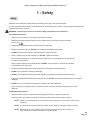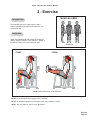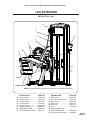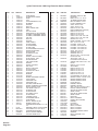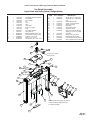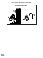
1
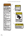
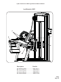
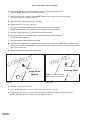
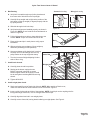
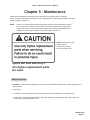
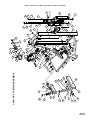
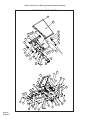
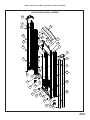
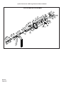
Cybex Total Access Leg Extension
Owner’s and Service Manual
Strength Systems
Part Number 14051-999-4 D
www.cybexinternational.com
Cybex Total Access Leg Extension
Owner’s and Service Manual
Strength Systems
Part Number 14051-999-4 D
Cybex® and the Cybex logo are registered trademarks of Cybex International, Inc.
VR3® and its mark are registered trademarks of Cybex International,Inc.
DISCLAIMER: Cybex International, Inc., makes no representations or warranties regarding the contents of this manual. We reserve the right to
revise this document at any time or to make changes to the product described within it without notice or obligation to notify any person of such
revisions or changes.
© Copyright 2010, Cybex International, Inc. All rights reserved.
Printed in the United States of America.
10 Trotter Drive Medway, MA 02053 • 508-533-4300 • FAX 508-533-5183
www.cybexinternational.com • [email protected] • 14051-999-4 D • May 2010
Table of Contents
Front Pages
Table of Contents . . . . . . . . . . . . . . . . i
Declaration of Conformity . . . . . . . . . ii
1 Safety
Safety . . . . . . . . . . . . . . . . . . . . . . . . .
Safety Guidlines and Practices . . . . .
Warning/Caution Decals . . . . . . . . . .
Regular Maintenance Activities . . . . .
Using Proper Form . . . . . . . . . . . . . .
1-1
1-2
1-3
1-6
1-6
2 Exercises
Intended Use . . . . . . . . . . . . . . . . . . . 2-1
Instructions . . . . . . . . . . . . . . . . . . . 2-1
3 Customer Service
Contacting Service . . . . . . . . . . . . . .
Ordering parts . . . . . . . . . . . . . . . . . .
Return Material Authorization (RMA).
Damaged Parts . . . . . . . . . . . . . . . . .
3-1
3-1
3-2
3-3
4 Assembly . . . . . . . . . . . . . . . . . . . . . 4-1
5 Maintenance
Daily Procedures . . . . . . . . . . . . . . . .
Weekly Procedures . . . . . . . . . . . . . .
Yearly Procedures . . . . . . . . . . . . . . .
Environment. . . . . . . . . . . . . . . . . . .
Storage . . . . . . . . . . . . . . . . . . . . . .
5-1
5-4
5-6
5-7
5-7
6 Service . . . . . . . . . . . . . . . . . . . . . . . 6-1
Page i
Page ii
This page intentionally left blank.
Cybex Total Access 14051 Leg Extension Owner’s Manual
1 - Safety
Safety
Read the Owner’s Manual carefully before assembling, servicing or using the equipment.
It is the responsibility of the facility owner and/or owner of the equipment to instruct users on proper operation of the
equipment and review all labels.
WARNING: Serious injury could occur if these safety precautions are not observed:
User Safety Precautions
•
Obtain a medical exam prior to beginning an exercise program.
•
Read and understand warning labels and user manual prior to exercising. Obtain instruction
prior to use.
•
Keep body and clothing free from and clear of all moving parts.
•
Inspect machine prior to use. DO NOT use if it appears damaged or inoperable.
•
DO NOT attempt to fix a broken or jammed machine. Notify floor staff.
•
Use the machine only for the intended use. DO NOT modify the machine.
•
Be sure that the weight pin is completely inserted. Use only the pin provided by the manufacturer.
If unsure seek assistance.
•
Never pin the weights in an elevated position. DO NOT use the machine if found in this condition.
See assistance from floor staff.
•
Children must not be allowed near these machines. Teenagers must be supervised.
•
DO NOT use if guards are missing or damaged.
•
DO NOT use dumbbells or other incremental weights, except those provided by the manufacturer.
•
Inspect all cables and belts and connections prior to use. DO NOT use if any components are worn, frayed or
damaged.
•
DO NOT remove any labeling from equipment. Replace any damaged labels.
•
Stop exercising if you feel faint, dizzy or experience pain at any time while exercising and consult your
physician.
Facility Safety Precautions
•
Read the Owner’s Manual carefully before assembling, servicing or using the equipment.
•
Securely anchor each machine to the floor using the anchor holes provided in each machine.
NOTE: Cybex is not responsible for the actual anchoring of equipment. Consult with a professional
contractor.
NOTE: Use fasteners having a minimum of 500 lbs. tensile capacity (3/8” grade 2 bolts or better).
NOTE: If legs/frame does not contact surface, DO NOT pull down with anchors. Shim any
leg or frame not in contact with surface using flat washers.
Safety
Page 1-1
Cybex Total Access 14051 Leg Extension Owner’s Manual
•
Make sure that each machine is set up and operated on a solid level surface. Do not install equipment on an
uneven surface.
•
Make sure that all users are properly trained on how to use the equipment.
•
Make sure there is enough room for safe access and operation of the equipment.
•
Perform regular maintenance checks on the equipment. Also pay close attention to all areas most susceptible to wear,
including (but not limited to) cables, pulleys, belts and grips.
•
Immediately replace worn or damaged components. If unable to immediately replace worn or damaged components
then remove from service until the repair is made.
•
Use only Cybex supplied components to maintain/repair the equipment.
•
Keep a repair log of all maintenance activities.
•
Inspect all cables and belts and connections prior to use. DO NOT use if any components are worn, frayed or
damaged.
NOTE: It is the sole responsibility of the user/owner or facility operator to ensure that regular maintenance is performed.
Safety Guidelines And Practices
Cybex recommends that all fitness equipment be used in a supervised area. It is recommended that the equipment be
located in an access controlled area. Control is the responsibility of the owner. The extent of control is at the discretion of
the owner.
It is the responsibility of the purchaser/user of Cybex products to read and understand the owner’s manual, and warning
labels; as well as instruct all individuals, whether end users or supervising personnel, on proper usage of the equipment.
PROPER USAGE:
Use machine only as described in the manual. Failing to follow proper instructions may result in injury.
Do Not Lean Against or Pull On the framework, weight stack, or any component, whether machine is at rest or in use.
Inappropriate or improper use may result in injury to users or third parties (bystanders).
Do not use machine if it is not located on a solid level surface or is improperly installed.
Provide an adequate safety perimeter between the machine, walls and other equipment to ensure that the facility has the
proper clearance for usage and training.
SECURING EQUIPMENT:
The machine has holes in the feet, which allow for ease in anchoring to the floor. Cybex strongly recommends that,
to eliminate rocking, tipping or falling over due to incorrect usage and misuse, equipment be secured to a solid, level
surface.
1. The solid, level surface should not deviate more than 1/8” over a 10’ distance or as defined and required by local
building and architectural codes.
2. Anchoring of equipment must be completed by a qualified licensed contractor.
Safety
Page 1-2
Cybex Total Access 14051 Leg Extension Owner’s Manual
3. Anchoring holes are provided on the feet of the frame. All anchoring locations must be used when anchoring the
equipment to the floor.
4. Due to the wide variation of flooring on which machines may be anchored or installed, verify anchoring method and
anchoring fasteners with a qualified and licensed contractor.
5. A minimum pull out force of 220 lbs/100 kgs is required for each anchor position..
6. Do not use machine until it is properly anchored.
MAINTENANCE:
Preventative maintenance allows proper equipment operation and reduces the risk of injury. Perform the maintenance
requirements as specified in the manual.
STANDARD COMPLIANCE:
Cybex products meet or exceed applicable ASTM and EN Standards.
Warning/Caution Decals
Warning decals indicate a potentially hazardous situation, which, if not avoided, could result in death or serious injury.
Caution decals indicate a potentially hazardous situation, which, if not avoided, could result in minor or moderate injury.
The warning and caution decals are shown on the following page. The diagrams following the decals show where each
decal is located.
Safety
Page 1-3
Cybex Total Access 14051 Leg Extension Owner’s Manual
A
CAUTION
B
C
CAUTION
D
CAUTION
Personal injury may occur.
Keep away from moving
parts to avoid injury.
4000Y316-4 A
Safety
Page 1-4
Cybex Total Access 14051 Leg Extension Owner’s Manual
Leg Extension 14051
C
C
D
A
B
Description
Part No.
A. Warning Label....................4605-381-4
B. Caution Decal.....................4520-362-4
C. Caution Decal.....................8500-026-4
D. Caution Decal.....................4000Y316-4
Safety
Page 1-5
Cybex Total Access 14051 Leg Extension Owner’s Manual
Regular Maintenance Activities
Preventative maintenance activities must be performed to maintain normal operation of your equipment.
Keeping a log sheet of all maintenance actions will assist you in staying current with all preventative
maintenance activities. The preventative maintenance actions are described in detail in Chapter 5.
Briefly, they include:
Daily
1. Clean upholstery.
Weekly
1. Inspect all nuts and bolts for looseness. Tighten as required.
2. Inspect all cables and belts for damage or wear (see Chapter 5). If a cable or belt is worn
or damaged, immediately discontinue use until cable or belt has been replaced.
3. Check for worn handles, worn snap links, and worn warning labeling. Replace all worn parts
immediately.
4. Inspect for loose or worn grips. Replace all worn grips immediately.
5. Inspect weight stacks for proper alignment and operation. Correct all improper alignment
and operation issues immediately.
6. Lubricate guide rods using automotive engine oil only.
Yearly
1. Replace all cables and belts at least annually.
Using Proper Form
Before working out, read and understand the exercises located on the placard and in Chapter 2.
Safety
Page 1-6
Cybex Total Access Owner’s Manual
2 - Exercise
MUSCLES USED
Intended Use
The intended use of this equipment is to aid or
improve general physical fitness and exercise. For
commercial use.
Instruction
Read and understand all instructions and warnings
prior to using this machine. See Chapter 1, Safety, in
the Owner’s Manual or consult with floor staff.
Quadriceps,
START
FINISH
NOTE: Motion Developed: Knee Extension
NOTE: Do not turn knob when weight stack is elevated.
NOTE: All adjustment points on the machine have yellow handles or knobs.
NOTE: See next page for “Set Up” and “Movement.”
Exercise
Page 2-1
Cybex Total Access Owner’s Manual
Set Up - Consult floor staff if assistance is required.
1. Adjust back pad so when seated, knees align with machine’s axis of rotation.
2. Comfortably position shin pad and apply light pressure.
3. Grasp handles and stabilize body.
Movement
1. Push forward and up against ankle pad until legs are straight.
Exercise
Page 2-2
Cybex Total Access Owner’s Manual
3 - Customer Service
Contacting Service
Hours of phone service are Monday through Friday from 8:30 a.m. to 6:00 p.m. Eastern Standard Time.
For Cybex customers living in the USA, contact Cybex Customer Service at 888-462-9239.
For Cybex customers living outside the USA, contact Cybex Customer Service at 508-533-4300
or fax 508-533-5183.
Find information on the web at www.eCybex.com or by e-mail at [email protected].
Ordering Parts
Fax your order to 508-533-5183. To speak with a customer service representative, call 888-462-9239 (for
customers living within the USA) or 508-533-4300 (for customers outside the USA). You may also contact
us through e-mail at [email protected].
Having the following information ready when calling will assist our Cybex representatives in serving you.
•
Unit Serial Number
•
Product Name
The unit serial number and product name can be found on the serial number decal. See Chapter 6 for
exact location of serial number decal.
•
Part Description
•
Part Number
Part descriptions and part numbers are located in Chapter 6 of this manual.
•
Shipping Address
•
Contact Name
In addition to your shipping address and contact name, your account number is helpful but not required.
Customer
Service
Page 3-1
Cybex Total Access Owner’s Manual
Return Material Authorization (RMA)
The Return Material Authorization (RMA) system outlines the procedures to follow when returning material
for placement, repair or credit. The system assures that returned materials are properly handled and analyzed.
Follow the following procedures carefully.
Contact your authorized Cybex dealer on all warranty-related matters. Your local Cybex dealer will request
a RMA from Cybex, if applicable. Under no circumstances will defective parts or equipment be accepted by
Cybex without proper RMA and an Automated Return Service (ARS) label.
1. Call the Customer Service Hotline listed above for the return of anything that is defective.
2. Provide the technician with a detailed description of the problem you are having or the defect in the item
you wish to return.
3. Provide the model and serial number of your Cybex equipment.
4. At Cybex’s discretion, the technician may request that you return the problem part(s) to Cybex for evaluation
and repair or replacement. The technician will assign you a RMA number and will send you an ARS label.
The ARS label and the RMA numbers must be clearly displayed on the outside of the package that contains
the item(s) to be returned. Include the description of the problem, the serial number of the Cybex equipment
and the name and address of the owner in the package along with the part(s).
5. Forward the package through UPS to Cybex.
Attn: Customer Service Department
Cybex International, Inc.
1975 24th Ave SW
Owatonna, MN 55060
NOTE: Merchandise returned without an RMA number on the outside of the package or shipments sent COD
will not be accepted by the Cybex receiving department.
Customer
Service
Page 3-2
Cybex Total Access Owner’s Manual
Damaged Parts
Materials damaged in shipment should not be returned for credit. Shipping damages are the responsibility
of the carrier (UPS, Federal Express, trucking companies, etc.)
Apparent Damage - Upon receipt of your shipment, check all items carefully. Any damage seen with a
visual check must be noted on the freight bill and signed by the carrier’s agent. Failure to do so will result
in the carriers refusal to honor your damage claim. The carrier will provide you with the required forms for
filing such claims.
Concealed Damage - Damage not seen with a visual check upon receipt of a shipment but noticed later
must be reported to the carrier as soon as possible. Upon discovery of the damage, a written or phone
request to the carrier asking them to perform an inspection of the materials must be made within ten
days of the delivery date. Keep all shipping containers and packing materials as they will be needed in
the inspection process. The carrier will provide you with an inspection report and the necessary forms for
filing a concealed damage claim. Concealed damage claim is the carrier’s responsibility.
Customer
Service
Page 3-3
Cybex Total Access Owner’s Manual
This page intentionally left blank
Customer
Service
Page 3-4
Cybex Total Access Owner’s Manual
4 - Assembly
TOOLS REQUIRED
•
•
•
•
•
7/32” Allen wrench
1/8” Allen wrench
Medium weight automotive engine oil
Torque wrench
3/4” Wrench
NOTE: Two people will be required for this procedure.
NOTE: It is the responsibility of the facility owner/owner of the equipment to ensure that there
is appropriate clearance around each machine to allow for safe use and passage.
NOTE: Refer to chapter 6 for reference diagrams.
1. Read and understand all instructions thoroughly before starting any of
the procedures listed on this instruction sheet.
2. Verify you have received the appropriate configuration.
A. Verify that you received the correct color machine that you ordered.
B. Verify you received the proper weight stack.
C. Verify you received the appropriate owner’s manual.
D. Verify you received the warranty sheet.
E. Verify you received the weight stack decals.
3. Move to desired location.
4. Remove shipping feet.
WARNING: Use extreme caution when removing shipping cones and installing feet.
Failure to do so could result in injury.
A. With an assistant, carefully remove each (standard) cone-shaped shipping support
using a 3/4” socket or wrench.
B. Cut shipping tie securing top weight.
C. Carefully place rubber feet (supplied with machine) on each foot of the frame.
5. Installing the weight stack.
A. If weight stack is already installed, proceed to step 9.
B. Using a 1/8” Allen wrench, remove the two Button Head Socket Cap Screws (BHSCS) securing the
bottom bracket to the frame. NOTE: Do not remove middle BHSCS securing shroud to bottom bracket.
C. Remove the remaining BHSCS securing the back shroud to the frame. NOTE: After final BHSCS
is removed shroud will slide down to the floor with bottom support bracket attached.
D. Carefully slide shroud out of machine.
Assembly
Page 4-1
Cybex Total Access Owner’s Manual
E. Slide spring loaded top guide rod cap down guide rod until guide rod cap is clear
of frame. NOTE: Top guide rod cap is spring loaded.
F. Slowly release grasp of guide rod cap. NOTE: Guide rod cap contains a compression spring
that will fly if grasp is not released slowly.
G. Remove guide rod cap and spring and set aside.
H. Repeat steps 5F-5H for other rod guide.
I.
Carefully lean guide rods slightly outward, away from machine to clear pulley.
NOTE: Excessive pressure on guide rods may damage lower guide rod caps.
J. Slide top weight up and out of machine and carefully set it aside.
K. Wipe guide rods clean over entire length. Lubricate with light coating of medium
weight automotive engine oil.
L. Have an assistant hold the guide rods vertical.
M. Carefully align weight plate over guide rods and slowly lower weight plate. NOTE: When installing weight
plates, position plates so wide edges of bushing face upward and narrow edges of bushing face downward.
See Figures 1A and 1B.
N. Repeat step 5M-5N to install each weight plate.
T
C
E
RR
CO
WIDE bushing
edge faces
upward
Figure 1A
G
N
RO
W
NARROW
bushing edge
NOTE: The narrow bushing
edge must face downward.
Figure 1B
O. Slide top weight over guide rods.
P. Place springs and guide rod caps on guide rods (removed from step 5G).
Q. Compress guide rod caps and ailgn guide rod caps with weight frame holes and secure in place.
NOTE: Guide rod caps must snap or lock into weight frame holes.
Assembly
Page 4-2
Cybex Total Access Owner’s Manual
6. Belt Routing.
Correct belt routing
A. Verify belt is routed through top of pulley bracket and
then route end of belt down to the top weight.
Wrong belt routing
Insert
Insert
Belt
Belt
B. Carefully lift top weight and verify that the position of the
belt clamp (on the top weight) is aligned properly with the
top pulley bracket.
Stem
Stem
C. Slide belt through slot in belt clamp.
Figure 2A
D. Verify belt and insert are installed properly, as shown in
Figure 2A. NOTE: Do not install the insert backwards as
shown in Figure 2B.
Front
E. Pull belt tight and secure belt to clamp with the two set
screws. NOTE: Torque set screws 300-350 in./lbs.
Back
F. Place weight stack pin in each plate to verify proper
installation.
G. Without selecting any resistance, lift top weight up
and down (simulating normal operation).
H. Have an assistant verify that the belt is moving
smoothly and is routed straight from the top
pulley bracket to the top weight belt clamp.
I.
Figure 2B
Figure 3
Guide Rod
Turn the Increment Weight Adjusting Knob to
select 0 lbs or 0 kg.
7. Install back shrouds.
9.0
Weight Stack
1
A. Carefully place shroud into position.
2
3
4
B. Starting at the bottom replace the two
BHSCS (removed in step 5D) to secure
bottom support bracket to the shroud. Install
but do not tighten remaining BHSCS securing
shroud.
5
6
Pounds
7
8
9
10
C. Tighten all BHSCS.
18.0
36.0
45.0
54.0
63.0
Kilograms
72.0
81.0
90.0
99.0
Figure 4
8. Install weight plate decals.
A. Slowly and carefully peel off back side of decal. NOTE: When peeling off back cover,
make sure that the decals remain attached to the front sticker. Figure 3.
B. Insert a guide pin through each hole of the template. NOTE: A guide pin can be anything that fits
through the weight stack hole, such as a weight stack selector pin.
C. Carefully align decal and rub it onto weight plates.
D. Carefully remove front side, leaving decals adhering to weight plates. See Figure 4.
Assembly
Page 4-3
Cybex Total Access Owner’s Manual
NOTE: It is important that you perform regular inspection and maintenance activities on your equipment.
See the CYBEX Owner’s Manual for inspection and maintenance activities. If you do not have a
CYBEX Owner’s Manual or if you have any questions or concerns, call CYBEX Customer Relations
at 888-462-9239.
9. Verify proper operation
10. Securely anchor machine to the floor.
A. Securely anchor machine to the floor using
the anchor holes provided in each machine.
NOTE: Cybex is not responsible for the actual anchoring of equipment. Consult with a professional contractor.
NOTE: Use fasteners having a minimum of 500 lbs. tensile capacity (3/8’’ grade 2 bolts or better).
NOTE: If legs/frame does not contact surface, DO NOT pull down with anchors. Shim any leg or
frame not in contact with surface using flat washers.
Assembly
Page 4-4
Cybex Total Access Owner’s Manual
Chapter 5 - Maintenance
All preventive maintenance activities must be performed on a regular basis. Performing
routine preventive maintenance actions can aid in providing safe, trouble-free operation of all Cybex
Strength Systems equipment.
NOTE:
Cybex is not responsible for performing regular inspection and maintenance actions
for your machines. Instruct all personnel in equipment inspection and maintenance
actions and also in accident reporting/recording. Cybex phone representatives are
available to answer any questions or concerns that you may have.
NOTE: All inspections and
repairs must be
performed by trained
service personnel only.
Cybex will void warranty if
non-Cybex replacement parts
are used.
Daily Procedures
1. Upholstery - Wipe down all upholstery as per the recommendations listed below for light soiling and more
difficult stains.
Light Soiling
• A solution of 10% household liquid dish soap with warm water applied with a soft damp cloth.
• If necessary, a solution of liquid cleanser and water applied with a soft bristle brush. Wipe away the
residue with a water dampened cloth.
Maintenance
Page 5-1
Cybex Total Access Owner’s Manual
More Difficult Stains
• Dampen a soft white cloth with a solution of 10% household bleach (sodium hypochlorite), 90% water.
Rub gently. Rinse with a water dampened cloth to remove bleach concentration.
• The same procedure can be used with full strength household bleach, if necessary.
• Allow bleach to puddle on the affected area or apply with a soaked cloth for approximately 30 minutes.
Rinse with a water dampened cloth to remove any remaining bleach concentration.
Alternative Method for Difficult Stains
• Dampen a soft white cloth with rubbing alcohol and rub gently. Rinse with a water dampened cloth to
remove any remaining rubbing alcohol concentration.
NOTE: To restore luster, a light coat of spray furniture wax can be used. Apply for 30 seconds and follow
with a light buffing using a clean white cloth.
Please Review Carefully
When using strong cleaning agents such as rubbing alcohol or bleach, it is advisable to first test in an inconspicuous area. Other cleaning agents may contain harsh or unknown solvents and are subject to formula
changes by the product manufacturer without notice. Should you desire to use other cleaning agents, carefully
try them in an inconspicuous area to determine potential damage to the material. Never use harsh solvents or
cleaners which are intended for industrial applications. To clean stained or soiled areas, a soft
white cloth is recommended. Avoid use of paper towels.
Cleaning products may be harmful/irritating to your skin, eyes, etc. Use protective gloves and eye protection. Do
not inhale or swallow any cleaning product. Protect surrounding area/clothing from exposure. Use in a well ventilated area. Follow all product manufacturer’s warnings. CYBEX and its vendors cannot be held responsible for
damage or injuries resulting from the use or misuse of cleaning products.
2. Frames - Wipe down all frames using a mild solution of warm water and car wash soap. Be sure to dry
thoroughly. AVOID acid or chlorine based cleaners and also cleaners
containing abrasives as these could scratch or damage the equipment.
3. Chrome - Clean chrome tubes, first using chrome polish and then using a car wax seal.
Neutral cleaners with a pH between 5.5 and 8.5 are recommended. Be sure to dry
thoroughly. AVOID acid or chlorine based cleaners and also cleaners containing abrasives
as these could scratch or damage the equipment.
Maintenance
Page 5-2
Cybex Total Access Owner’s Manual
4. Guidelines for cleaning front panel:
•
Use clean soft cloths or sponges for application of cleaners and again for washing and rinsing.
•
Follow up the application with warm water rinse.
•
Don’t use abrasives or high alkaline cleaners.
•
Don’t leave cleaners on for long periods, wash immediately.
•
Don’t apply cleaners in direct sunlight or at elevated temperatures.
•
Don’t use scrapers, squeegees or razors.
•
Don’t clean with gasoline.
5. Compatible Cleaners and Detergents:
•
Formula 409
•
Top Job
•
Joy
•
Palmolive
•
Windex with Ammonia D
6. To Minimize Fine or Hairline Scratches:
Mild automotive polish applied and removed with a soft, clean cloth will help fill scratches.
7. Suggested Polishes:
•
Johnson Paste Wax
•
Mirror Glaze #10 Plastic Polish (by Mirror Bright Polish Co.)
•
Novus Plastics Polish #1, #2 (by Novus Inc.)
Maintence
Page 5-3
Cybex Total Access Owner’s Manual
Weekly Procedures
1. Check all nuts and bolts for looseness. Tighten as required.
2. Inspect all belts (entire length) for any non-uniformity and wear.
Immediately replace belt if any of the following conditions are present:
Maintenance
Page 5-4
Cybex Total Access Owner’s Manual
3. Some machines use cables in addition to belts. Inspect all cables for wear or damage and proper
tension. When inspecting cables, run your fingers on the cable, paying particular
attention to bends in the cable and attachment points.
Replace all worn cables immediately. The following conditions may indicate a worn
cable:
•
A tear or crack in the cable sheath that exposes the cable. See Figure 1
Figure 1
•
A kink in the cable. See Figure 2.
Figure 2
•
A curled sheath. See Figure 3.
Figure 3
•
“Necking”, a stretched cable sheath. See Figure 4.
Figure 4
Maintenance
Page 5-5
Cybex Total Access Owner’s Manual
4. Inspect bars and handles for wear, paying particular attention to tab area connecting
points.
Replace all worn handles immediately.
5. Inspect snap links for proper latching (indicates wear).
Replace all worn snap links immediately.
6. Inspect for loose or worn grips.
Replace all loose or worn grips immediately.
7. Inspect all labeling for readability. This includes instructional placards, warning and caution decals.
Replace all worn labeling immediately.
8. Inspect all weight stacks for proper alignment and operation.
Correct all improper alignment and operation issues immediately.
9. Wipe Weight Stack Guide Rods clean over entire length. Lubricate with a light coat of medium
weight automotive engine oil.
Yearly Procedures
1. Replace all belts and cables at least annually.
Maintenance
Page 5-6
Cybex Total Access Owner’s Manual
Environment
Static Electricity - Depending upon where you live, you may experience dry air, causing a common
experience of static electricity. This may be especially true in the winter time. You may notice a static
build-up just by walking across a carpet and then touching a metal object. The same can hold true while working out on your unit. You may experience a shock due to the build-up of static electricity on your body and the
discharge path of the unit. If you experience this type of situation, you may want to increase the humidity to a
comfortable level through the use of a humidifier.
Humidity - The unit is designed to function normally in an environment with a relative
humidity range of 30% to 75%.
NOTE: Do not install or use the unit in an area of high humidity, such as in the vicinity of a steam room, sauna,
indoor pool or outdoors. Exposure to extensive water vapor, chlorine and/or bromine could adversely
affect the electronics as well as other parts of the machine.
Temperature - The unit is designed to function normally in an environment with an ambient temperature range
o
o
o
o
of 50 F (10 C) to 104 F (40 C) degrees.
Storage
Humidity - The unit can be shipped and stored in an environment with a relative humidity range of 10% to 90%.
NOTE: Do not store the unit in an area of high humidity, such as in the vicinity of a steam room, sauna, indoor
pool or outdoors. Exposure to extensive water vapor, chlorine and/or bromine could adversely affect the
electronics as well as other parts of the machine.
Temperature - The unit can be shipped and stored in an environment with an ambient temperature range of 32
o
o
o
F (0 C) and 140 F (60 C) degrees.
o
Maintenance
Page 5-7
Cybex Total Access Owner’s Manual
This page intentionally left blank
Maintenance
Page 5-8
Cybex Total Access Owner’s Manual
6 - Service
Please refer to the next several pages for parts lists, exploded-view diagrams and cable
and belt routing diagrams.
NOTE: All inspections
and repairs must be
performed by trained
service personnel only.
Cybex will void warranty if
non-Cybex replacement parts
are used.
Service
Page 6-1
Cybex Total Access Owner’s Manual
This page intentionally left blank
Service
Page 6-2
Cybex Total Access 14051 Leg Extension Owner’s Manual
LEG EXTENSION
PRODUCT NO. 14051
A
F
C
G
L
C
H,I
C
E
B
D
P
N
Q
J,K
M (Both Sides)
NOTE: See exploded-view diagram for location of O (serial number decal).
DESCRIPTION
A.
B.
C.
D.
E.
F.
G.
H.
PART NO.
Placard Decal .................... 14051-598
Warning Decal.................... 4605-381
Caution Decal ................... 8500-026
Caution Decal .................... 4520-362
Caution Decal .................... 4000Y316
Weight Stack Belt 87”.........GB000202
Water Bottle Holder.............13000-400
Seat Pad w/Wear Cover..... 4800-131
DESCRIPTION
PART NO.
I. Wear Cover.......................... 4800-134
J. Leg Pad w/Wear Cover....... 4800-006
K. Wear Cover................. ....... 4800-093
L. Back Pad............................ 4800-176
M. Grip 6.50”.............................4605-507
N. Grip.......................................11090-385
O. Serial Number Decal
P. Weight Selector Pin............ BH030207
Q. Increment Weight Decal..... 14000-407
Service
Page 6-1
Cybex Total Access 14051 Leg Extension Owner’s Manual
ITEM
QTY
1
2
3
4
5
6
7
8
9
10
11
12
13
14
15
16
17
18
19
20
21
22
23
24
25
26
27
28
29
30
31
32
33
34
35
36
37
38
39
40
41
42
43
44
45
46
47
48
49
50
51
52
53
54
55
56
57
1
1
2
1
1
1
1
2
2
1
1
2
1
1
1
2
4
1
1
1
1
1
1
1
1
1
1
1
1
3
2
2
4
1
1
2
4
1
1
2
1
2
2
1
1
1
1
1
1
1
1
1
1
1
1
1
1
08229
11040-301
11040-440
11050-333
11050-400
11050-407
11050-408
11090-374
11090-376
11090-385
12000-466
12000-387
12000-392
12000-394
12000-395
12000-396
12000-398
12000-406
12050-200
12050-202
12050-204
12050-209
12050-214
12050-216
12050-342
12050-343
12050-345
12050-351
12050-355
12050-368
12050-369
12050-370
12050-375
12050-377
12060-201
12060-350
12090-322
12100-303
12101-300
12102-330
12102-339
12210-347
12210-348
13000-400
13000-402
14000-400
14051-007
14051-201
14051-202
14051-203
14051-204
14051-300
14051-307
14051-310
14051-311
4605-511
4715-346
58
59
60
61
62
1
1
2
1
1
51198
BS070201
BS070208
CM000211
FB030239
Service
Page 6-2
PART NO.
DESCRIPTION
ITEM
QTY
PART NO.
P/PIN,DETENT
CLAMP BLOCK INSERT
KNOB
CAM
COUNTERWEIGHT (3.87)
RETAINER
SPACER
END CAP
RING, HANDLE GRIP
GRIP
PULLEY COVER
EXTRUSION, INC WT CHANNEL
CHANNEL, INCREMENT WEIGHT
CHANNEL, INCREMENT WEIGHT
TOP CAP
END CAP
SPACER
PANEL INSERT
W MAIN FRAME
W CUSHION BAR
W CAM PLATE
W COUNTERWEIGHT MOUNT
MOUNTING BRACKET
W INPUT ARM
ECCENTRIC PLATE
WASHER
MOUNT, CAM FOLLOWER
PLATE, DECAL, CAM
ROTATION DECAL
LINK, SEAT MOUNT
ENDCAP
SPRING, TORSION
PIN, PIVOT
DECAL, START RLD
W PIVOT SHAFT
WT ROD .625 X 54.63
FOOT PAD
BUMPER
SPACER
INSERT, INCREMENT WEIGHT
STOP GUARD
GUIDE ROD CAP
GUIDE ROD CAP
HOLDER, WATER BOTTLE
MOUNT, WATER BOTTLE HOLDER
DECAL, WEIGHT PLATE
TOP WEIGHT ASSY 15
W DETENT LINK
W SEAT MOUNT
W/ HANDLE, PIVOT
W SEAT BACK
P DETENT PLATE
ADJUSTMENT DECAL
P/PIN,DETENT
DECAL, DETENT PLATE
INSERT,PLASTIC 5.94
COMPRESSION SPRING .72 x 1.50
LG
WARRANTY BOOK (NOT SHOWN)
COM SPRING .56 x .66 1.50 LG
COMPRESSION SPRING
DECAL, PATENT PENDING
CAM FOLLOWER 10mm
63
2
FB030249
64
65
66
67
68
69
70
8
2
65”
2
2
1
1
72
73
74
75
76
77
78
79
80
81
82
83
84
85
86
87
11
2
3
1
1
2
12
1
2
2
7
3
1
2
3
10
FB130205
FC030009
GB000202
gp000209
HC622815
HC622820
HC700414
HC700416
HC700417
HC700428
HC700430
HD303312
HD303315
HF449063
HF579000
HH320030
HN575100
HN625200
HN704901
HN704902
HP707017
HS347600
HS347700
HT512517
88
1
HT552515
89
4
HT570410
90
91
92
93
94
95
96
97
98
99
100
101
102
103
104
105
106
107
108
109
110
111
112
113
114
115
116
117
118
119
120
121
122
12
2
3
9
3
6
1
6
2
2
4
3
2
2
2
3
1
1
1
1
1
1
1
2
1
1
1
4
1
1
4
1
1
HX570412
HY740000
JC620422
JC700420
JC700422
JC700924
JC780417
JS347400
PN660200
PP130002
PP130003
PP660006
PR060005
PR069400
4605-507
PR740300
4800-131
4800-134
4800-006
4800-093
4800-176
4605-381-4
14051-999-4
14040-409
14051-998-4
11040-216
4000Y316-4
8500-026-4
4520-362-4
14000-407
HS307602
11040-790
12100-312
DESCRIPTION
BEARING, RADIAL 35 MM
EXT RACE
BRG,FLG .62 x .75 .38 LG
TOLERANCE RING 72MM
BELT .95 WIDE X 7.25 FT
PULLEY ASSEMBLY-3.50
SHCS .250-20 X .250
SHCS .250-20 X 1.25
BHSCS .375-16 X .625
BHSCS (REMOVED 5/28/2010)
BHSCS .375-16 X 1.00
BHSCS .375-16 X 2.25
BHSCS .375-16 X 2.50
S BOLT .250 X .500 .190-10-24
S BOLT .250 X .750 .190-10-24
INSERT 3/4 X 1/4-20
PANEL FASTNER, 10-24 U TYPE
KEY .313 X .313 X 2.50
LOCKNUT .190-No 10-24
LOCKNUT, .250-20 NYLON
LOCKNUT, .375-16 NYLON
LOCKNUT, .375-16 NYLON
STUD, .375-16 X 1.00
WASHER, SAE .375
WASHER, USS .375
TAP SC 10-24 X 1.00 TYPE WB
PN HD PHIL BLK
TAP SC NO. 8-16 X .75
PLASTITE PN HD PHIL BLK
SCREW, PNH TORX 10-24 X .375,
BLACK
BHSCS, 10-24 X .50, SS
SET SCREW
BHSCS .250-20 x 1.50
BHSCS .375-16 X 1.25
BHSCS .375-16 X 1.50
FHSCS .375-16 X 1.75
BHSCS .500-13 X 1.00
LOCKWASHER, INT TOOTH .375
INSERT, PLASTIC 1.00 DIA-11 GA
INSERT, DOMED PLASTIC
INSERT, DOMED PLASTIC
PLUG, SNAP IN
BUMPER, WEIGHT
BUMPER, RECESS
GRIP 1.38 OD X .94 ID X 6.50LG
MOUNT, CENTER BONDED
SET PAD W/ WEAR COVER
WEAR COVER
LEG PAD W/ WEAR COVER
WEAR COVER
BACK PAD
DECAL, WARNING
MANUAL (NOT SHOWN)
BUMPER
PLACARD
BELT CLAMP
DECAL, CAUTION
DECAL, CAUTION
DECAL, CAUTION
INCREMENT WEIGHT DECAL
WASHER
DECAL, MADE IN U.S.A.
BUMPER
97
74
68
24
56
100
103
103
68
84
3
108
116
96
29
26
100
109
97
74
20
14051 VR3 TA MAIN ASSEMBLY
39
63
65
117
101
65
101
19
23
63
11
73
94
105
117
117
73
17
61
82
86
Serial Number
89
67
23
82
17
82
17
45
87
66
44
43
102
47
2
19
36
88
87
17
67
60
42
91
43
102
47
Torque Set Screws
300-350 in/lbs
115
36
60
42
Cybex Total Access 14051 Leg Extension Owner’s Manual
Service
Page 6-3
Cybex Total Access 14051 Leg Extension Owner’s Manual
LEG EXTENSION SEAT ASSEMBLY
106
107
49
97
93
92
100
8
93
77
100
104
92
9
98
8
49
97
93
77
82
104
9
101
19
98
82
99
74
117
93
110
51
64
97
118
72
81
64
120
122
30
120
33
76
81
92
99
97
75
52 55
72
57
10
54 69
38
72
80
50
48
64
64
99
30
72
Service
Page 6-4
93
33
19
31
32
Cybex Total Access 14051 Leg Extension Owner’s Manual
LEG EXTENSION PANEL ASSEMBLY
16
14
15
90
87
90
90
18
78
114
78
78
78
87
90
16
13
90
78
90
78
90
90
87 78
12
113
90
78
119
40
78
121
111
90
78
87
78
113
12
40
90
Service
Page 6-5
Cybex Total Access 14051 Leg Extension Owner’s Manual
LEG EXTENSION RLD ASSEMBLY
5
72
95
83
21
34
7
3
28
1
41
59
22
25
6
4
95
53
95
27
62
93
91
Torque Set Screws
300-350 In./Lbs
72
35
63
65
70
19
65
63
39
96
24
Service
Page 6-6
29
26
101
79
2
Cybex Total Access 14051 Leg Extension Owner’s Manual
Top Weight Assembly
(Light Stack and Heavy Stack Configurations)
ITEM
1
2
3
4
5
6
7
8
9
10
11
12
13
14
15
16
QTY
PART NO.
DESCRIPTION
1
1
2
2
1
1
1
1
1
1
1
4
2
1
1
2
11040-366
11040-367
11040-369
11040-370
11040-427
11040-426
11040-424
11040-416
11040-425
BH030207
4700-251
BR030209
BR030220
HP016820
HP266765
HS720004
Top Weight Assembly, Molded
Hub, Molded
Rod, Linkage
Pin
Rod
Stem
Cover Plate
Cover, Top Weight
Knob
Pin, Weight Selector
Lifting Post 15
External Retaining Ring .188
Internal Retaining Ring 1.250
Cotter Pin .125 X 1.25
Roll Pin, .125 X .938
Felt Washer, .641 1.250 .125 T
ITEM
QTY
PART NO.
17
18
4
4
HT562715
HT582510
19
20
21
22
23
24
25
2
12
6
1
1
1
1
11040-409
11040-572
11040-573
11040-216
11040-301
11040-428
HT552512
26
27
27
28
29
3
11
14
1
1
HY740000
4000C101
4000C101
12050-020
12070-021
DESCRIPTION
Tap SC NO 10 x .750 F Phil
Tap SC NO 10 x .375 PN HD
Phil
Molded Bumper Pad
Guard, Increment Weight
Weight Increment
Belt Clamp
Clamp Block Insert
Adjustment Decal
Screw, Pan HD Phil HD Self
Tapping 8-16 x .50, Type WB
Set Screw
Weight Plate Light Stack
Weight Plate Heavy Stack
Light Weight Pack (Not Shown)
Heavy Weight Pack (Not Shown)
23
26
22
TOURQUE SET SCREWS
300-350 IN./LBS
8
12
3
2
3
4
12
14
13
5
16
15
25
1
6
4
7
18
10
9
24
21
20
17
19
11
NOTE: Increment weights are located
in the increment weight channel.
See main assembly.
27
Service
Page 6-7
Cybex Total Access 14051 Leg Extension Owner’s Manual
Belt Routing Assembly Detail
66
66
Service
Page 6-8
10 Trotter Drive Medway, MA 02053 • 508-533-4300 • FAX 508-533-5183
www.cybexinternational.com • [email protected]