1
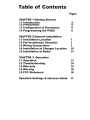
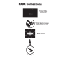
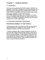
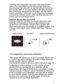
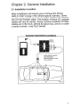
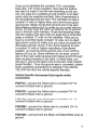
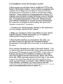
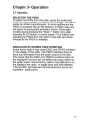
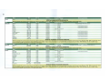
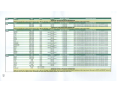
Add an Auxiliary Input to
Your Factory Radio
Owner's
Manual
PXDX
AuxBox
Table of Contents
Pages
CHAPTER 1-Getting Started
1.1 Introduction
1.2 Precautions
1.3 Configuration & Harnesses
1.4 Programming the PXDX
4
4
5
6
CHAPTER 2-General Installation
2.1 Installation Location
2.2 Pre-Installation Checklist
2.3 Wiring Connections
2.4 Installation at Changer Location
2.5 Installation at Radio
7
8
8
10
11
CHAPTER 3 -Operation
3.1 Operation
3.2 Troubleshooting
3.3 Warranty
3.4 Warning
3.5 FCC Statement
13
14
15
16
16
Dipswitch Settings & Harness Guide
17
PXDX Connection s
Factory Radio
(not included)
Vehicle Specific Harness
( actual harness may vary)
PXDX Interface
Chapter 1- Getting Started
1.1 Introduction
Thank you for purchasing the PXDX auxiliary Interface, by
iSimple®. The PXDX is designed to provide endless hours of
listening pleasure through most vehicles' factory radios. To
ensure that your interface performs correctly in your car or
truck, we recommend that you read this entire manual before
attempting installation of the PXDX interface.
The PXDX interface will allow you to connect your audio
source to a factory radio that has the ability to control a CD
changer. The PXDX is designed to be used with any audio
source with a 3.5mm audio output.
1.2 Precautions (Important, Please Read).
PREVENTING DAMAGE TO YOUR VEHICLE.
To eliminate the risk of an electrical short, we recommend
disconnecting the car battery in most vehicles, prior to
installation except in the following situations:
• Vehicles equipped with on-board navigation should not
have the car's battery disconnected. Doing so may cause
loss of memory settings. These settings would then have
to be reprogrammed by an authorized car dealer for a fee
to be paid by the vehicle's owner. For these vehicles, we
recommend extreme caution when handling exposed 12V
power or ground wires/connectors.
4
•Vehicles that incorporate a security-code protecting the
radio. If the car's battery or the radio's power plugs are
disconnected, the radio will not operate without re-entering
the security-code. If you have access to the security-code,
feel comfortable disconnecting the battery and the radio's
power connectors. Otherwise, do not disconnect the battery
and exercise extreme caution while handling exposed 12V
power or ground wires/connectors.
PROPER MOUNTING LOCATION .
Securely install the interface in a location free from; heat,
humidity, moving parts or direct sunlight. Beware of hotair flow from your vehicle's climate control system. We
recommend securing the interface to a suitable location, free
of sharp metal edges, using; double sided tape, Velcro or
wire ties.
PXDX Interface
Aux Cable
Vehicle Specific Harness
1.3 Configuration and Harness Selection
This section will instruct you on how to properly identify and/
or confirm the proper interface dip-switch configuration and
vehicle specific harness selection.
Use the guide located in the back of this manual on page 18
to locate your vehicle, inform you of the proper dip-switch
configuration for the interface, and the vehicle specific
harness that you will need for your particular vehicle.
Depending on the type of PXDX kit you purchased, it might
include a bundle of different vehicle harnesses or none at all.
If the kit contains many harnesses, only one will be needed
for your specific vehicle. If the kit came without any vehicle
harness, your authorized iSimple® dealer will have the
harness for you to purchase separately.
5
As you consult the application guide, please take a moment
to review our IMPORTANT COMPATIBILITY NOTES listed
with each of the vehicle manfactuers. These notes will
inform you of any issues or circumstances that can affect the
compatibility of our product with your factory audio system
and accessories. Some situations result in the loss of use
of some factory audio players. Please read and understand
these notes before proceeding with the installation.
1.6 Programming the PXDX
Now that you have identified the correct harness and dipswitch configuration using the application guide, it is now
time to program the interface. To program the interface, set
the dip-switches located on the side of the interface (see
Fig.1 below) to the congfiguration listed for your vehicle in
the application guide. Switches are in their default setting of
"off' in the up positior and are turned "on" when switched
down. This programs .he PXDX to work with the vehicle
in which it will be inst ,JIIed. The dip-switches MUST be set
before the interface 1s plugged into the vehicle. Otherwise
the PXDX will not work correctly.
Fig.1 Side view of Interface with dip switches
12345678
DIP
ON+
Please Refer to Page 18 for Configuration Settings
6
Chapter 2- General Installation
2.1 Installati on Location
Most installations will require you to remove the factory
radio in order to plug in the vehicle specific harness. Some
vehicles may require you to connect the interface to a factory
pre-run CD changer cable. The location of these CD changer
cables will vary by vehicle. Some common locations of these
cables are in the trunk, behind the glove box, and in or under
a center console. (see Fig.2 below)
Common Connecti on Location s
Vehicle Specific Harness
(Sold Separately)
Refer to Application Guide
correct harness
Fig. 2
7
2.2 Pre-Installation Checklist
At this time and before beginning the installation
please ensure that:
• You have read and understand the precautions
outlined in section 1.2
• You have your radio's security code.(when
applicable, see section 1.2)
• The dip-switch~s on the interface have been
set with the proper configuration. (see section
1.3)
• You have in your possession the correct
harness for your vehicle. (see sec. 1.3)
• You have determined your installation location.
(see section 2.1)
If any of these steps has not been taken,
STOP. Only when ALL of these steps have been
taken should you proceed with the rest of the
installation.
2.3 Wiring Connections
Some vehicle specific harnesses require wiring connections
that involve splicing of wires. If you are not confident in
making these connections to your radio's wiring harness, we
recommend you seek professional installation. You can visit
www.isimplesolutions.com and click on the dealer link at the
top of the page to find an authorized professional installer.
Make these connections only after verifying the proper circuit
on your radio harness with a voltmeter. With the key OFF
and the negative test lead of the voltmeter firmly touching a
bare metal chassis part of your car, begin probing the wires
in the main radio harness with the positive test lead. The
constant 12V+ circuit should read a continuous 12 volts or
higher.
8
Once you've identified the constant 12V+ circuit, strip
back about 1/8" of the insulation. Now take the positive
test lead and insert it into the wire stranding so that you
can now probe for a suitable ground location in the dash
cavity using the negative test lead. Bare chassis metal is
the recommended ground spot. The voltmeter will read a
constant 12 volts or higher when you have found a good
ground point. Attach the BLACK ground wire to this spot
with either an existing bolt or screw or use a metal piercing
screw. You also have the option of splicing into the ground
wire in the main radio harness. Probe the remaining wires
with the negative test lead until you again find a circuit that
reads a constant 12 volts on the voltmeter. When you've
found a circuit that reads constant 12 volts, turn the dash
light dimmer control to make sure you have not probed the
illumination dimmer circuit. If the circuit continues to read
a constant 12 volts or higher regardless of the dimmer
position, you have found the ground wire. If not, continue
testing until you do. Some vehicles do not have a ground
wire in their main radio harness and instead ground through
their mounting brackets to the dash. In these cases, you
will have to ground the black wire to the bare metal chassis
inside the dash . Once the ground wire is connected, please
finish your wiring connections by splicing in the external
YELLOW wire from the vehicle specific harness.
Vehicle Specific Harnesses that require wiring
connections:
PXHFD1 - connect the Yellow wire to constant 12V+ &
connect the Black wire to ground.
PXHFD2 - connect the Yellow wire to constant 12V+ &
connect the Black wire to ground.
PXHFD3 - connect the Yellow wire to constant 12V+ &
connect the Black wire to ground.
PXHGM3 - connect the Yellow wire to constant 12V+ &
connect the Black wire to ground.
PXHVW2 - connect both the Black and Black/White wires to
ground.
9
2.4 Installation at the CD Changer Location
In this section you will learn how to install the PXDX in the
factory CD changer location. If your vehicle is equipped with
a factory CD changer you will need to disconnect it from
the factory pre-run harness in order to connect the PXDX
interface. If your vehicle is not equipped with a factory CD
changer, you will need to locate the factory pre-run harness.
This may involve the removal of the; center console, glove
box, or carpeted side panels in the trunk. Please consult
your vehicle's dealership or a local car audio professional
for instruction or assistance with locating the factory CD
changer connection if necessary.
1. Connect your vehicle specific Harness to the factory prerun CD changer harness in the vehicle.
2. Make any necessary wiring connections on your vehicle
specific harness. Please see section 2.3 for details on
making these wiring connections.
3. Now that the interface is connected to the radio, you
will need to test the operation of the interface before
permanently running the silver aux cable or re-assembling
the dash.
First, connect the silver aux cable to the audio source. Turn
on the factory radio and press the button that would activate
the factory CD changer to select the PXDX. It may take up
to three minutes for the interface to initialize to the radio
(this only happens the very first time you select the PXDX).
Once the PXDX has been selected, press Play on the audio
source. You should be able to hear the music from your
audio source through your factory radio. With the operation
of the interface confirmed, you may continue with the
installation. If you experience difficulties in operation, please
see our troubleshooting chart in section 3.2.
10
4. Decide on a convenient location to mount your audio
source.
5. Run the aux cable from the interface to the desired
mounting location. Use caution to not cut, pinch, or crimp
the cable during this step. Avoid moving parts, vehicle wiring
harnesses and areas of excessive heat when routing the
cable.
6. Secure the interface in the vehicle using; double sided
tape, Velcro or wire ties. Make sure to check for proper
clearance and avoid moving parts. Take into account the size
of the interface and the wire harness and do not force the
interface and harness into a space that is too tight, damage
to the harness may result.
7. Now that the interface is secured and the aux cable has
been run, you are ready to enjoy your audio source in your
vehicle!
2.5 Installation at the Radio
In this section you will learn how to irlstall the PXDX behind
the radio. If your vehicle is equipped with a factory CD
changer or other external audio source, you will need to
disconnect it from the back of the radio in order to connect
the PXDX interface.
1. Carefully remove the radio from the vehicle. If your radio
uses a Security Code, make sure that you have the code
before unplugging the radio. Some vehicles require the use
of special tools to remove the radio. Please consult your
vehicle's dealership or a local car audio professional for
instruction or assistance with radio removal if necessary.
2. Make any necessary wiring connections on your vehicle
specific harness. Please see section 2.3 for details on
making these wiring connections.
3. Connect the Vehicle Specific Harness to the CD changer
port on the back of the radio. Be sure to make a firm
connection but do not force it. If there is difficulty making the
·connection, please consult the application guide to confirm
your vehicle specific harness selection.
11
4. Now that the interface is connected to the radio, you
will need to test the operation of the interface before
permanently running the silver aux cable or re-assembling
the dash.
First, connect the silver aux cable to the audio source. Turn
on the factory radio and press the button that would activate
the factory CD changer to select the PXDX. It may take up
to three minutes for the interface to initialize to the radio
(this only happens the very first time you select the PXDX).
Once the PXDX has been selected, press Play on the audio
source. You should be able to hear the music from your
audio source through your factory radio. With the operation
of the interface confirmed, you may continue with the
installation. If you experience difficulties in operation, please
see our troubleshooting chart in section 3.2.
5. Decide on a convenient location to mount your audio
source.
.,.
6. Run the aux cable from the interface to the desired
mounting location. Use caution to not cut, pinch, or crimp
the cable during this step. Avoid moving parts, vehicle wiring
harnesses and areas of excessive heat when routing the
cable.
7. Secure the interface in the dash cavity behind the radio
using; double sided tape, Velcro or wire ties. Make sure to
check for proper clearance and avoid moving parts. Take into
account the size of the interface and the wire harness and
do not force the interface and harness into a space that is
too tight, damage to the harness may result.
8. Now that the interface is secured and the aux cable has
been run, you may reinstall the radio and replace any panels
that may have been removed to access the radio. You are
ready to enjoy your audio source in your vehicle!
12
Chapter 3- Operation
3.1 Operation
SELECTING THE PXDX
To select the PXDX from the radio, press the button that
would normally activate the factory CD changer. This button
varies by vehicle manufacturers. In some applications the
PXDX is accessed like an XM reciever, In these cases you
will press the appropriate activation button. Some radio
models require pressing the "Seek >" button once, after
pressing the CD button. In some cases, if it is the first time
selecting the PXDX from the radio it may take up to three
minutes for the PXDX to initialize.
RADIO DISPLAY DURING PXDX OPERTION
Some factory radio's may show DISC and TRACK numbers
on the display of the radio. The PXDX interface does not
send any information from the audio so~rc.e to the radio.
This means that the DISC and TRACK numbers shown on
the display will not and can not reflect the song number on
the audio source. Some factory radio's may flash zero's on
the display of the radio, or toggle back and forth between
1:00 and 2:00. All these are normal behaviors and do not
represent a malfunction.
13
3.2 Troubleshooting
Symptom
Cause
Remedy
No Power
Blown fuse in vehicle fuse
block.
Replace fuse with same
amp rating. If the fuse
blows again, call tech
support.
No Power
Bad connection.
Check cable and wiring
connection.
Alternator noise is heard
(Changes with Engine RPM)
Improper wiring creates a
ground loop.
Install a Ground loop isolator or seek professional
service from a local car
audio shop.
Radio is not recognizing
PXDX interface
Wrong configuration on the
interface.
Select the right pconfiguration for your car. (See
section 1.3).
Radio is not recognizing
PXDX interface
Bad cables or cables are
not connected properly
between converter box and
car radio
Check connection and
cables, push in firmly.
Radio is not recognizing
PXDX interface
Yellow and black wires are
not connected to Constant
12V+ and Ground. (When
applicable).
Please read wiring instructions in chapter 2 of this
manual and see if your car
requires to connect the
yellow and black cable to
power and ground.
Audio is Low or
Distorted
PXDX interface is connected with an external CD
changer or other external
factory audio source.
Disconnect the factory
external audio source.
14
3.3 Warranty
One Year Limited Warranty
The quality controls used in the manufacture of this product
This warranty covers any supplied or manufactured parts
of this product that, upon inspection by iSimple authorized
personnel, is found to have failed in normal use due to
defects in material or workmanship. This warranty does not
apply to installation expenses.
Attempting to service or modify this unit, operating this unit
under conditions other than the recommended voltage will
render this WARRANTY VOID.
Unless otherwise prescribed by law, iSimple shall not be
liable for any personal injury, property damage and or any
incidental or consequential damages of any kind (including
water damage) resulting from malfunctions, defects, misuse,
improper installation or alteration of this product.
All parts of this iSimple product are guaranteed for a period
,
of 1 year as follows:
Within the first 12 months from date of purchase, subject
to the conditions above, iSimple will repair or replace the
product at their discretion, if it is defective in material or
workmanship providing it is returned to an Authorized
iSimple's Dealer, with PROOF OF PURCHASE from an
authorized iSimple dealer.
15
3.4 Warning
This equipment may be reset by unintentional electrostatic
discharge during operation. Exposure to direct sunlight or
extreme heat may cause damage or malfunction.
3.5 FCC Class B Radio Frequency Interference
Statement
This equipment has been tested and found to comply with
the limits for a Class B digital device, pursuant to Part
15 of FCC rules. These limits are designed to provide
reasonable protection against harmful interference in a
residential installation. This equipment generates, uses,
and can radiate radio frequency energy and, if not installed
and used in accordance with the instructions, may cause
harmful interference to radio communications. However,
there is no guarantee that interference will not occur in a
particular installation. If this equipment does cause harmful
interference to radio or television reception, which can be
determined by turning the equipment off and on, the user is
encouraged to try to correct the interference by one or more
of the following measures:
1. Reorientate or relocate the receiving antenna.
2. Increase the separation between the equipment and
receiver.
3. Connect the equipment into an outlet on a circuit different
from that of which the receiver is connected.
4. Consult the dealer or an experienced radio I television
technical for help
Notice : The changes or modifications not expressly
approved by the party responsible for compliance
could void the user authority to operate the equipment. ·
16
Make
Acur•
va..
1998· 2000
1996-1997
1998- 2001
1992-1997
1992-1995
1998 -2002
1996-1997
200 2
1999-2002
1996-1997
1992·1994
2003-20 07
All Years
All Years
All Years
Model
Cl
Cl
Integra
Integra
Legend
RL
Rl
RSX
TL
TL
Vigor
All Models
MDX
SLX
NSX
Vehocla Specofic Notes
Dip Swotch Settings"
1 .4 .8 ON
1.4.8 ON
1.4.8 ON
1.4.8 ON
1.4.8 ON
1.4.8 ON
1.4.8 ON
1.4.8 ON
1.4.8 ON
1.4.8 ON
14.8 ON
Harness
PXHH01
PXHCH2
PXHH01
PXHCH2
PXHCH2
PXHHD1
PXHCH2
PXHHD1
PXHHD1
PXHCH2
PXHCH2
Port II
PXOX
PXOX
PXOX
PXOX
PXOX
PXOX
PXOX
PXDX
PXDX
PXOX
PXOX
Not Compettble
Not Compettble
Not Compettble
Not Com ttbla
IMPORTANT ACURA APPUCATION INFORMATION
PXOX: Not: COMPI!dble wkh OftV fKtwy O:.IW:rulaudio NYI"Ce auch ••: JCM tYMf', CO c........... w
uoll 114iA c4 clwl-. Not co.--JWo wftlo . . . .atioa rMiH.
~Audl
Year
1998-2004
1998-2004
odel
All Models !Except 9elowl
All Models !Exce t Eelowl
Port II
PXOX
PXDX
c:a.u.a:. ,a.yw. TheM Mvlc:et •lollt M
4hcea~ duriftt
cbe la.C.UKio• oM wilt no •nger fuftCtion. N ot; CHI!pHIIM wkJII f.ctory re11i01 tNt h..w an In
Dop Swotch Settings•
Harness
1.8 ON
PXHAD1
1.8 ON
PXHAD2 ~ PXJ-IVW2•
IMPORTANT AUOI APPUCATION INFORMATION
PXDX: Not eomptU•I• • lth •ny fKtOf'Y external oudio source euch ••: XM t:unor. CO cMn..r,
Of' C.~
Vehicle Specific Noua
Connect at pre-wored 13-pon cable on the laf1; rear t runk
player. T1M:M HvJc.n •u•t M di-.cOftnKCH durlne cht lnecall.c:ton end will no lon..,. funcdon'" Vehlclea wfth S'fmphony eound ayetema mat:.,..
epec_lal ad•pu:r harnHI PXHA02 01 . .u oa PXHVW2 and con.ftiKC at radio.
~Buick
Year
1997·2003
1999-200 2
1995·2005
2005
1995-2003
2003-2005
1996- 1999
1995-1996
2005
2005
odel
Century
Le Sabre
Park Ave
Reinter
Regal
Rendezvous
RMere
Roadmaster
Allure
laCrosse
Port II
PXOX
PXOX
PXOX
PXDX
PXOX
PXOX
PXOX
PXOX
Harness
PXHGM1 & GMH32T
PXHGM3
PXHGM1 & GMH32T
PXHGM3
PXHGM1 & GMH32T
PXHGM3
PXHGM1 & GMH32T
PXHGM1 & GMH32T
••
Dip Switch Settings•
3.80N
1.3.8 ON
3.90N
1.3.80N
3.80N
1.3.80N
3,80N
3.80N
Vehicle Specific Notes
Must usa GMH32T 1'"-harness chen plug • PXHGM1 behond radio.
Must usa GMH32T 'T"-hamess then plug •PXHGM 1 behind radoo
Must use GMH32T 'l'"·harness t hen plug •PXHGM1 behtnd radoo
Must use GMH32T 'l'"·hamess then plug •PXHGM 1 behond redoo.
Must usa GMH32T 1'"-hamess then plug •PXHGM1 behond redoo.
IMPORTANT BUICK APPUCATION INFORMATION
or-,..,_.,""'-
4evlceo • - lie 4 1 - 411ri... tlool....,n.deo- wtU,.. IINitor f - . OM wA!cleo 1111 - lt004- .ppM ,.;a, a faaory
PXDX: Nciot . . .,.uw.- ooy IKto<y • • -l ou4io ...,,... ouc:h oo: XIII to...,., CD cho-.
..... may not be eWe c.·~ aft en.emaJ device.. n..r.fore the PXOX INY MC. M ce.,.dw.. If ,.. are an u.perie.-cM ln.utaw, 'fOil cen recaln XM.. PIMae viaJt -.,..o-.HM.~ rw t~K!Mla . 119,..1999 RHioe with llluUc 1ft CD,...,.... lb.C*pt
funct;l....._
cenc:rol
cM,...r
CO
heve
ftOC
H
cMy
co.p-.dlt..
NOT
.,..
Corwect.el
Mc•u••
Cadillac
odel
Catenl
DeVIlle
ElDorado
Escalade
Escalade
Seville
Year
2001
1995-2003
1995-2002
1999-2002
2003-2006
1995-2005
Part If
PXOX
PXOX
PXOX
PXDX
PXOX
PXOX
Hernns
D1p Switch Settings•
PXHGM2
3.8 ON
PXHGM2
3.8 ON or 1 3.8 ON
PXHGM2
3.8 ON
PXHGM 1
3.8 ON
PXHGM3
1 .3.8 ON or 2.3.8 ON
PXHGM2
3.8 ON
IMPORTANT CADIU.AC APPUCATIDN INFORMATION
Veh1cla Specific Notas
Behind rlldoo or Trunk. Mount•ng Locatooo
Bah•nd rlldoo or Trunk Mountong Locatooo
Trunk Mounting Locatoon
PXOX: Hot e.M,.tu~.. wiU. erwy fKCN"y on.Nal avdio aource auch n.; XM tvner. CO c.h•nter• w CuMtte ,-,.... ... TMM H¥ka "'UK IN lllfsconnectM durine dMt fnsca"-don an.- will eo..,.._,. funcUN. OM wtdc... 1111 - 2004 '""e41ul,.., widt •
......._,. .... IMt be: able to au,.rc. an QAt'MI device.
t:he PXOX aay Me M COMtNt;lblo. If you are an ta peMa~ lnRahr. you e.an rwt.ain XU. Pie. . . visit: -.pa~Hio.co• for Ht;alla . 111$.1111 Ra4la wfth ._ultt In CD ,t-v-r CE.acept
Corwccel are NOT c. .,.atiW. McawM t:hey 4o ..- h•ve CO c.M,...r COM"rol fuftct:Softt.
The,..,.,.
Make
Chevrolet
Make
Chevrolet
Model
Astro Van
Avalanche
Avalanche
Blazer
Camaro
Cavalier
Cavaher
Color ado
Corvette
Corvette
Impala
Impala
Lum1na
Mahbu
Monte Cllrio
Model
Monte Certo
S1lverlldo
S1lveredo
Suburban
Suburban
Tahoe
Tahoe
Treolblner
Venture
Venture
Yur
1996-2005
2002
2003-2006
1998-2002
1997·2002
1996-1999
2003-2005
2005
1997-2004
1997-2004
1995·1999
2000-2005
1996-1999
1997-2000
1995-1999
Year
2000-2005
1996-2002
2003-2006
1995-2002
2003-2006
1995-2002
2003-2006
2002-2007
1997-1999
2004-2005
Part II
PXOX
PXOX
PXOX
PXOX
PXOX
PXOX
PXOX
PXOX
PXOX
PXOX
PXOX
PXOX
PXOX
PXOX
PXOX
Par-e II
PXOX
PXOX
PXOX
PXDX
PXOX
PXOX
PXOX
PXOX
PXOX
PXOX
r~
Hernen
Dip Switch Settings •
Vehicle Specific Notu
PXHGM1
3,80N
PXHGM 1
3,80N
PXHGM3
1.3.8 ON
PXHGM1
3.8 ON
PXHGM1
3,8 ON
PXHGM1
3.8 ON
PXHGM3
1.3.8 ON or 2.3.8 ON
PXHGM3
1.3 ,8 ON
PXHGM2
3.80N
Trunk Mounting Loce~ion
PXHGM4
3 .80N
As a substitute. Clln oleo use PX HGM1 and GMH20T Harnesses
PXHGM1
3.80N
1,3,8 ON
PXHGM3
3,80N
PXHGM1
PXHGM 1
3,80N
PXHGM1
3,80N
Harness
Oop Switch Settings•
Vehicle SpeciOc Not. .
PXHGM3
3.8 ON
PXHGM1
3.8 ON
PXHGM3
1 .3.8 ON
PXHGM1
3,8 ON
PXHGM3
1 .3.8 ON
PXHGM1
3 .9 ON
PXHGM3
1 .3.8 ON
PXHGM3
1 .3.8 ON or 2 .3.8 ON
PXHGM1
3.8 ON
PXHGM3
1 .3.8 ON or 2,3.9 ON
IMPORTANT CHEVROLET APPUCATIDN INfORMATION
not.._.,,_.
P JCDX; NM. CMJ,.·tJWe wfch •f'Y ~ oxtere~~l ev4io source sueb as; JlM tuner. CD chengor. er C.a..ue ,eayer. TheM llevlcea Must 1M di:scon:nerted during dte IMt.-lletJon aM wUt M liNter tuMdM. GM vehlc-. 1111 ... ZOCM
alave ,..., Nt M .~.. to aupport: an o~l tlwiee. TherefON c::he PXOX aMI'f not M C:OftlpetUt... If yw.,.. afl . .,.,..•eM ln.c•lt.f'. you can rec.atn )(M. Plea. . visit .p.caev41o. c. . for dn..tla •• 111S..1.11 Radios wiU. kitt le CO
c.tw«e) ON NOT coe,.cltiiM ltecauM they tlo ~flaw CD con...- control functJon•.
Make
Chrysler
Model
All Models
All Models
All Models
Pac1foca
Sebl'lng
Year
2002-2005
1999--200 1
1995-1999•
2006
2006
Part #
PXOX
PXOX
PXOX
PXOX
PXOX
~leyor
wkh • fKt:oot'y
lE•cept:
Hornell
01p Sw1tch Settings•
Vehicle Spotcllic Not.ea
PXHCH3
4,8 ON
Must be non-CAN8US, If red10 IS an REF.REC,RAO. RAJ< senes, vehiCles are not compatible
PXHCH2
4,8 ON
• 1999 Radios w1th rounded comers use PXHCH2
PXHCH1
1 .4.8 ON
•1999 Radoos w1th squar-e comers use PXHCH1
PXHCH3
4,8 ON
PXHCH3
4,8 ON
IMPORTANT CHRYSLER APPUCATIDN INFORMATION
PXDX: Not compatible with any factory utef"ftal audio •ourco auch at: JCM t.YftOf', CO ch• "tlr, or CaaHtco ,layer. Theta devfcot "'uac be dls.connoct:od during the ln.sullatJon and will no tongor function. To docormlno If yow,. 2002-.200!1 vohlclo •• c.om,.tJble.
tKtory rotflo mutt hl vt "Oitk .... . on ,,... .t 1 . Vehlt-lt mutt be no....CANBUS, It rotllo Ia •" AEF.AEC. AAD. AAI( aeries , vt hlcltt ore not c:.oMpatlble. The Nrlt t It lndlcaUd on tht t·f'Ont of the retUo. 1111 Chrytltr vthlcltt h•vt ont ol c;wo dllftNnt ..tyt• ra4lu..
ThHo two rodlot utt different horntt ..... Tht th•pe of tttt Ndlo ltct will dtCtNftlnt whi"Ch hiHitll you will VI I. U your Ndlo ftce It SOUA.Ae , you wiU uti tht horn••• port• P XHCH1 . If your rodlo toc1l• OVAL !rounded cornorel, you will uto the hornnt
IINI"'' PXHCHI .
eke
Dodge
Madel
All Models
All Models
All Models
Vcu
2002-2005
1999•-2001
1995-1999•
Pe~
#
PXOX
PXOX
PXOX
Vehlcla Specrlic Noua
Dip Switch Settings•
Hernua
- . , . oot ~
Must be non-CANBUS. d , _ •.., REF.REC.RAO RAJ( 4 ,8 ON
PXHCH3
•1999 Rad1os w1th rounded corners use PXHCH2
4.8 ON
PXHCH2
1,4,8 ON
PXHCH1
•1999 Rad1os With s uere comers use PXHCH1
IMPORTANT DODGE APPUCATION INFORMATION
,...,.t
be tUsc.onMC'te4 duri"t thelnsulln:i on aM witl no ton. . r futtet.:1oft. To det.e""lne if your 2002·2005 vehk:Je itl com,.db...
PXDX: Not. c. .,.cttt._ wflh eny IM10ry eatef"ftal audio source auc:h aa: XM tuur, CD ctlangor, or Ca•aet:c. ,teyer. ThoH devicn
1 . Vehicle muu be IMn..cANIUS, If rHio Ia In IIU(I, AEC,IItAO. Uk Mrlea, vehlciH are not. com,.tJbla. The A:rieals lndJc-.4 on tl'la front of ttM ,.adlo. 1111 Chryeter whfctee have one of c.wo dl,.,..nc. nyle radios.
f.c:tory NHIIIo IIIUtat h.we ..Oiak ... . Oft
TMN two rHJoe u•• different hemn.... TM ahape of the radio f.ct~ will doAMftiM wftlch hi,.,IN pu wUf UH. U you,. ra4fe face le SQUARE, you will use the hamen part# PXHCH1. tf your radio fKa Ia OVAL Crounded cof"MMraJ, yov will use t :he hal"fte:S:s
,,..He
, ...... PlCHCH2.
Eegle
All Models
1995-1998
PXOX
1,4.8 ON
PXHCH1
IMPORTANT EAGLE APPLICATION INFORMATION
All models must have "01sc
A
•
rlnted on Preset Sutton II 1
PXDX: N ot COM,atlblo with eny fecury utoMII audio source tuch at: XM tunaf", CD cha,..er, Of" C1aeette playe r. Thea• devk:ea muat tM ditconnectatl du..tnv the lnat.allet.ion 1nd wUI no longer function. U yeur vehicle le equipped wlth • f1etory CD changer,
you MUat: dlacennect It In order to 1M able to lnRall tM Interface. You will ktae the uu of Ute factory CO ch•ntef" to gain uea of your au• Input.
Ford
Crown V1ctoria
Crown V1ctone
Crown Vtetoria
Escape
Econol1ne
Econollne
Escort
El<curs10n
El<ped1tl0n
El<ped•toon
El<plorer
El<piOrer
El<plorer
Freestar
F-senes Pick Up
F-senes Plck Up
Focus
Mustang
Ranger
Ranger
Sport Tree
Taurus
Thunderbtrd
W1ndstar
1998-2003
1995-1 997
1995-1997
2001-2004
1998· 2004
199 7
1997-2004
2000-2004
1999·2002
1997-1998
1998· 2004
1995-1997
1995-1997
2004
1998-2003
1995-1997
2000-2003
2001 -2003
1998-2004
1995-1997
2000· 2004
1996·2005
2000- 2004
1999 -2004
PXOX
PXOX
PXOX
PXOX
PXOX
PXOX
PXOX
PXOX
PXOX
PXOX
PXOX
PXOX
PXOX
PXOX
PXOX
PXOX
PXOX
PXOX
PXOX
PXOX
PXOX
PXOX
PXOX
PXOX
PXHF03
2.80N
2,8 0 N
PXHF02
2,80N
PXHF01
PXHF03
2.80N
PXHF03
2.BON
2.BON
PXHF02
2.80N
PXHFD2
2.80N
PXHFD3
2.80N
PXHFD3
PXHFD2
2.80N
2 .80N
PXHF03
2.80N
PXHF02
PXHF01
2.80N
2.80N
PXHF03
2,80N
PXHF03
2.80N
PXHF02
PXHF04
2.80N
PXHF03
2.80N
2.80N
PXHF03
2.80N
PXHF02
2 .80N
PXHF03
2.80N
PXHF01
2,80N
PXHF03
2.80N
PXHF03
IMPORTANT FORO APPLICATION INFORMATION
•11 equipped w1th JBL. use PXHF01 at Rear Cont rol Untt 1n trunk
•tt equoppod With J8L, use PXHF01 at Rear Cont rol Unot •n t runk
Not compet1bla wrth lectory 1nstelled Sleupunkt r adiO
Trun~
Mount1ng Locatton
PXDX: N ot comp1t.lble with any factory uc-.erql audio source such u : XM tuMr, CO cha..-r. or C.e..cc-.e player. Ttt4tH ftovicu ..un be dlaconnect;H durtftll the 1nHIIletien and will no ktnter hlnccton. Noc COM,.tllrtte wfth factof'V N411Joa wkh )lul~n a..d.ll.c
CO ctt•ngo,... CoMpac1ble with fHtory nevltltfon rad.iot:.
0
"'
Make
Ford
Model
Crown Voctona
Crown Voctona
Crown Voctona
Year
1998- 2003
1995-1997
1995-1997
2001-2004
1998- 2004
1997
1997-2004
2000-2004
1999-2002
1997-1998
1998-2004
1995-1997
1995-199 7
2004
1998 -2003
1995 -1997
2000-2003
2001-2003
1998-2004
1995-1997
2000-2004
1996-2005
2000-2004
1999-2004
Escape
Econolone
Econolone
Escort
Excursoon
Elcpedotoon
Elcpedot oon
Elcplorer
Ex,plorer
Elc.p lorer
Freestar
F-seroes Pick Up
F-seroes Pick Up
Focus
Mustang
Ranger
Ranger
Sport Trac
Taurus
Thunderbird
Wondstar
.
.
Pan II
PXDX
PXDX
PXDX
PXOX
PXOX
PXDX
PXOX
PXOX
PXOX
PXDX
PXOX
PXOX
PXOX
PXOX
PXOX
PXOX
PXOX
PXOX
PXOX
PXOX
PXOX
PXOX
PXOX
PXOX
Huneu
Dop SIWitch Settings~
PXHF03
2 .80N
PXHF02
2 .80N
PXHF01
2 .80N
PXHF03
2 ,80N
PXHF03
2.80N
PXHFD2
2.80N
PXHF0 2
2.80N
2 ,8 ON
PXHFD3
PXHF03
2 ,8 ON
PXHFD2
2.8 ON
PXHF03
2,8 ON
PXHF02
2,8 ON
PXHF01
2,80N
PXHF03
2.80N
PXHFD3
2,80N
PXHF02
2.80N
PXHF04
2.8 ON
PXHF03
2.8 ON
2,8 ON
PXHF03
PXHF02
2.80N
PXHF03
2.BON
PXHF01
2.BON
PXHF03
2.80N
PXHF03
2.80N
IMPORTANT FORD APPLICATION INFORMATION
PXD.X! Nee c.••,.cl..._ wtttt uy r.uory aJlCef'ftal audio SOUf'CO such u : XM biMr. CD cha,...r, or Cn...cu pleyer.
Make
Honda
.
Madel
Accord
Accord
CMc
CMc
~
-
CRV
CRV
Del Sol
Element
lns1ght
Odyssey
Odyssey
Passport
Prelude
Prelude
52000
All Models
Accord
Polot
Ridgellne
92000
Year
1998-2002
1992-1997
1998-2004
1992-1997
1998-2004
1997
1993-1 997
2002
2001-2004
1995-1997
1998-2004
1998-2002
1998-2001
1992-1997
2000-2003
2005-2007
2003-2004
All Years
All Years
2004
Pan II
PXOX
PXOX
PXOX
PXOX
PXDX
PXOX
PXOX
PXDX
PXDX
PXOX
PXOX
PXOX
PXOX
PXOX
PXOX
Not Compatoble
Not Compattble
Not Compatible
Not Compatible
Not Compatible
Harnna
PXHH0 1
PXHCH2
PXHH0 1
PXHCH2
PXHHD1
PXHCH2
PXHCH2
PXHH01
PXHH0 1
PXHCH2
PXHH01
PXHH01
PXHH01
PXHCH2
PXHH01
n... 4ewlon Must. M
tiiKOn~
Vehicle Specific Nates
•rt equopped woth J8L. use PXHF01 at Rear Control Unot •n trunk
"If equopped wit h J8L. use PXHF01 at Rear Cont rol Unit In trunk
Not compatible woth fact ory Installed Blaupunkt radio
11""'-t tiM l...ua.tMn
Dip Switch Settings•
1.4.8 ON
1.4,8 ON
1.4,8 ON
1.4.8 ON
1.4.8 ON
1,4 ,8 ON
1 .4,8 ON
1.4.8 ON
1.4,8 ON
1.4.8 ON
1.4.8 ON
1.2.4.80N
1.4,8 ON
1.4.8 ON
1.4.8 ON
Trunk Mountong Locatoon
aM'"'' no loft9er fwncc.loft. Not. co,..patll»e wh:ft f.c:Ary radioa witt. ltuitt.-ln &-4isc:
Vehicle Specific Nates
IMPORTANT HONDA APPLICATION INFORMATION
PXDX: Not co•pac.lblo wtth any facc.orr • •tomat au41o aource 1uch aa: XM tvner. CO chan. .r• .,. Cae..ne playre,, Thew Hv5cae Muai be dlaconnecwct durolnt dMt ln.caltatlon en4 wilt no lont•,. f"nctlon. Not competlbte witft t•ct.ory r•dloe thee h•ve en In
•••~
I •••k C4l
ch•••••· Not cooo,..llolo
wit:~
no•••-• Mldloo.
M\Jst be non·CANBUS. If reooo iB an REF.REC.RAO. RAK senes.
-·ere
not cotnpet1blo
•1999 Radios w1th rounded corners use PXHCH2
compedb• wftll any fac!t.ory ut.ernal audio NUn::e 1uctl ••: XM tuner, CD c-hanger, or Cauette player. n.... devfcet, must: De d~nMC'tad during the ln•tellatlon aM will
ftO
kmgar tunctlo:n. To determine If your 2002· 2005 whlc .. I• Cotftpft:ible,
rMleo ""tilt hew -olall ..... ott~ 1. Vahle.. MUtt be no.CANIUS, If t"Mkt fa en AEF.A.EC,RAO. AAIC Mrfu, vehfca.. tre ~ comp.tdbla. The Hrl. . It lndiut.H on the front of the radio, 189• Chtyaler vehtcta haH OM of two dffferent ttyle "'"....
two redMn: uH tltffwrent hal'ftH--. The aha,. of Ute radio tHe will dderntine which hamn• you will u. .. If your riHIIo face le SQUARE, you wUI UM eM ...,....., p.~rt# PXHCH1. If Y®r radio rae. I• OVAL troundH comersl. you wUJ u•• the h•,.....•
,.,..., PXHCHt.
M•ke
Model
Continental
Continent al
Continental•
LS
Mark VIII
Nalligator
Nalligator
Car
Year
2002-2003
1998-2004
1995· 1997
1995·1997
2000-2003
1995-1998
1999· 2003
1997-1998
1998-2003
1995-1997
1998-2003
1995-1 997
1995-1997
1998·2004
1995· 1997
1995-1 997
1996-2005
1995· 2004
Part II
PXOX
PXOX
PXOX
PXOX
PXOX
PXOX
PXOX
PXOX
PXDX
PXOX
Harness
PXHF03
PXHF03
PXHFD2
PXHF01
PXHF03
PXHF02
PXHF03
PXHF02
PXHF03
PXHF02
Dip Switch Settings•
2,80N
2.80N
2,80N
2.80N
2.BON
2.80N
2,80N
2,80N
2.80N
2.80N
2.8 ON
2,8 ON
2,8 ON
2 .80N
2,8 ON
2.BON
2.80N
2.80N
Vehicle Specific Notes
•if equipped With JBL. use PXHF01 at Rear Control Un1t in trunk
•11 equ1pped w1th J8L. use P:XHF01 at Rear Control Un1t in trunk
•If equipped woth J8L. use PXHFD1 at Rear Control Unit on trunk
•11 equipped w1th J8L. use PXHF01 at Rear Control Unit In trunk
•11 equipped woth JBL, use PXHFD1 at Rear Control Un1t '" trunk
..
..
..
N iasan
Ouest
1999· 2002
PXOX
PXHF03
2 ,80N
IMPORTANT NISSAN APPLICATION INFORMATION
PXDX: Not compat-Ible wlch any fectory axc.maJ a.udlo source auc.h aa: XM tuner, CD changer, or Canet'te player. T'heH device• muat be dJa.connect:H during the lnauJietlon and wlll no longe r function .
..
Oldsmobile
Achleva
Alero
Alero
Aurora
Aurora
Bravacfa
Bravada
Cutlass
Cutlass Supreme
Eighty-Eight
Intrigue
LSS
Regency
Silhouette
Silhouette
1996· 1998
2003· 2004
1999· 2000
2001-2004
1995-1999
2004
1997-2001
1997-1999
1995-1997
19 96- 1999
1998-20 01
1996-19 99
1997-1998
2004
1996-1999
PXOX
PXOX
PXDX
PXDX
PXDX
PXDX
PXOX
PXDX
PXDX
PXDX
PXOX
PXOX
PXDX
PXDX
PXOX
••=
PXHGM3
PXHGM3
PXHGM2
PXHGM2
PXHGM2
PXHGM3
1,3,8
PXHGM 1
PXHGM2
PXHGM2
PXHGM2
PXHGM2
PXHGM2
PXHGM2
PXHGM3
PXHGM2
IMPORTANT OLOSMOBILE
1.3,80N
2.3,8 ON
3.80N
3.80N
3,80N
ON or 2.3.8 ON
3,9 ON
3,9 ON
3 ,9 ON
3 ,9 ON
3,BON
3 ,BON
3 ,BON
2.3.9 ON
3 .9 ON
APPLICATION INFORMATION
..
..
Trunk/CO Changer Mountong Locat ion
Trunk Mounting Location
Trunk Mounting Locatoon
Trunk Mount ing Location
Trunk Mounting
Trunk Mount1ng
Trunk Mounting
Trunk Mounting
Trunk Mounting
Trunk Mount ing
Locatoon
Location
Locatoon
Location
Location
Location
Trunk Mounting Location
PXOX: Not comp.etlbJe witt. any factory uternal audio source such
XM tuner, CD changer. or Caaaette pleyer. Then devices must ba dlaconnectad during the Installation and will n.o tonger function. CM vehicles 1998 - 2004 not equipped with a factory
alave may Mt be able to auppo~ an ••t ern.el device. Therefore the PXDX may no.t: be compltible. It you are an experienced Insulter. you can retain XM. Please vi aft www.p&c•eudlo.cortl fo,. detall.s . 1995-1999 Radios with built fn CD player lbc:ept
Co~) aN NOT comp.-tlble Hcauae they do not ha"• CO chanee,. control functions.
..
Plymout h
All Models
Neon
1995·2000
2002-2004
'
PXDX
PXOX
..
PXHCH1
1,4,9 ON
PXHGM3
1.4,8 ON
IMPORTANT PLYMOUTH APPLICATION INFORMATION
..
.
All models muse have "Disc
.
~
• prlntecf on Preset Button it 1.
PXDX: Not comp.tible with any f·a ctory external audio source such as: JtM tuner, CD changer. or Cassette player. TheM devices must be dlaconnected durlnt tf\elnttallat:Jon and will no longer function,
..
Pontiac
Aztec
Bonnevolle
Bonneville
Fleebird f Trans Am
GrandAM
Grand AM
Montana
Montana
Sunfire
Sunfire
TransSport
Vibe
G6
Gr and Pr1x
2003·2005
2000-2005
1996-1999
1996-2002
2003· 2005
1996-2000
2004-2005
1999 -2000
2003-2005
1996-1999
1996·1999
2004-2005
2005
2004-2007
PXDX
PXDX
PXDX
PXOX
PXOX
PXOX
PXOX
PXOX
PXDX
PXDX
PXDX
PXDX
Not Compatible
Not Comoatible
PXHGM3
PXHGM2
PXHGM 1
PXHGM 1
PXHGM3
PXHGM 1
PXHGM3
PXHGM1
PXHGM3
PXHGM1
PXHGM1
PXHGM3
1,3,8 ON or 2.3,8 ON
3,9 ON
3.8 ON
3,9 ON
1,3.9 ON or 2.3,9 ON
3.8 ON
1,3,9 ON or 2,3,8 ON
3.8 ON
1,3,9 ON
3,8 ON
3.9 ON
1 ,3,8 ON or 2.3,8 ON
,,
Trunk Mounting locatoon
IMPORTANT PONTIAC APPLICATION INFORMATION
PXDXt Not comp.atlb .. wich any facc.ory axcernalludlo aource such at: XM tune .., CD chaneer, or Casaette playe.r. The" de-vice• must be disconnected durlng the1nstallnlon and will no 1onger funC'tlon. GM vehicle• 1998 - 2004 not equipped wtth • fectory
alave may not be able to auppot"t an external device. Therefore the PXDJ( may not be c.ompat1ble. If you are an experienced lnat.aller, you can Ntain XM . Please viait www.pac-.~udlo.com for deuTia . 199$.1999 Radloa with built In CD player IEilCept
Corve-tte) are NOT compatible because e:hey do not: h•v• CD changer cone;rol funce:lons.
S•curn
All Models
1995- 1999
..
PIIDJI: -•••pKI•M _ , onyfocto<yo.....,...o..-._...
Scion
tC
xA
~tB
M •ke
2003-2007
2003-2005
2003-2005
--JIM-.
3.80N
.
we...-,....,.,.,_ _. _ .. - · - - - - -.. -
PXOX
PXHTY3
PXHTY3
PXHTY3
PXOX
PXOX
PXOX
PXOX
PXOX
PXOX
PXOX
PXOX
PXOX
PXOX
PXOX
.
IMPORTANT SATURN APPUCATION INFORMATION
c o -.
PXDX: Noc com,.aiiM wkh •nv r.ccorv eawmal eucllo source auch as: XM tuaer, co
M odel
Part N
Veer
1998-2005
PXOX
2006-2007
PXOX
PXOX
1998-2005
2006-20 07
PXDX
PXOX
1998-2005
PXDX
2006-2007
PXOX
1998-2005
PXDX
1998-2005
PXOX
2006-2007
Corolla
PXOX
2000-2005
Echo
PXOX
2001 -2004
Highlander
PXOX
2006-2007
Highlander
PXOX
1998-2005
Land Cruiser
PXOX
2006-2007
Land Cruiser
PXOX
2003-2004
Matn~
PXOX
2005-2007
Matnx
PXOX
2000-2005
MR2
PXOX
1998-2005
RAV4
PXOX
2001 -2005
SequoJO
PXOX
2006·2007
1999-2005
2006-2007
1998
1998
1998-2005
2006-2007
1998
2000-2007
PXHGM1
PXOX
c....,...,
IMPORTANT SCION APPUCATION INFORMATION
er C•~ player. TheM dewtcH Mvst M tllseottMCt.N 4uring tM: lnsufl.ec:ioft n4 will no ..neer fvaect.fl.
Vehicle Specific N otes
Dip Switch Settings•
H•rnesl
When using the PXHTY3 the green wires must be cut on
1.2.4 ,8 ON
PXHTY3
PXHTY3 or PXH2TY1
When us1ng the PXH1Y3 the green w1res must be cue on
1.2.4 .8 ON
When using the PXHTY3 the green wires must be cue on
1.2.4,8 ON
PXHTY3
PXHTY3 or PXH2TV1
When us1ng the PXH1Y3 the green w~res must be cue on
1.2.4 .8 ON
When us1ng the PXH1Y3 the green wires muse be cue on
1.2.4,8 ON
PXHTY3
PXHlY3 or PXH2TY1
When using the PXHlY3 t he green wires must be cue on
1.2.4.8 ON
When using the PXHlY3 Lho green wires must be cue on
1.2.4,8 ON
PXHTY3
When us1ng the PXHTY3 tho green wires must be cue on
1.2.4.8 ON
PXHlY3
1,2 ,4 .8 ON
PXHTY3 or PXH2TV1
When using the PXHTY3 tho green w1res must be cut on
When us1ng the PXHTY3 the green wires must be cut on
1.2.4.8 ON
PXHTY3
When using tho PXHTY3 the green w1ras must be cut on
1.2 .4 ,8 ON
PXHTY3
When using the PXHTY3 the green w1ras must be cut on
PXHTY3 or PXH2TY1
1.2.4.BON
When us1ng the PXHTY3 the green w1ras mus t be cut on
1.2,4 .80N
PXHTY3
When us1ng the PXHTY3 the green wires must be cut on
PXHTY3 or PXH2TY1
1.2.4.80N
1,3 ,80N
PXHGM3
When us1ng the PXHTY3 the green Wtres must be cut on
1,2,4.8 ON
PXHTY3 or PXH2TY1
When usmg the PXHTY3 the green w 1res must be cut on
1.2.4.80N
PXHTY3
When us1ng the PXHTY3 the green wtres must be cut on
1.2.4.80N
PXHTY3
When us111g the PXHTY3 the green WireS must be cut on
1.2.4.80N
PXHTY3
When ustng t he PXHTY3 the green wtres must be cut on
1.2.4 .80N
PXHTY3 or PXH2TY1
PXHTY3
PXHTY3 or PXH2TY1
PXHTY3
PXHTY3
PXHTY3
PXHTY3 or PXH2TY1
PXHTY3
PXHTY3
w
the PXHTY3 harness
the PXHTY3 harness
the PXHTY3 harness
the PXHlY3 harness
the PXH1Y3 harness
the PXHTV3 harness
the PXHTY3 horness
the PXHTV3 harness
the PXHTY3 harness
the PXHTV3 harness
the PXHTY3 hamess
the PXHTY3 harness
the PXHTY3 harness
the PXH1Y3 harness
the PXHTY3 harness
the PXHTY3 harness
the PXHTY3 hamess
the PXHTY3 harness
the PXHTY3 harness
USing
cut on
green Wires must
When us1ng the PXHTY3 the green Wires must be cut on t he PXHTY3 hamess
When using the PXHTY3 the green Wires must be cut on the PXHTY3 harness
When us111g the PXHTY3 the green w1res must be cut on the PXHTY3 harness
When us1ng the PXHTY3 the green w1res must be cut on the PXHTY3 harness
When using the PXHTY3 the green WireS must be cut on the PXHTY3 harness
When us1ng the PXHTY3 the green Wtres must be cut on the PXHTY3 hamess
When usong the PXHTY3 the green w1res mus t be cut on the PXHlY3 harness
When us1ng the PXHTY3 t he green wores must be cut on the PXHTY3 hamess
1.2.4.8 ON
1 2.4.8 ON
1.2.4.8 ON
1.2 .4 .80N
1.2.4 .8 ON
1.2 .4.8 ON
1,2.4.8 ON
1,2.4.8 ON
1.2.4 .8 ON
d~ri119
N
h i -..
When us1ng the PXHTY3 the green w 1res must be cut on the PXHTY3 harness
When using the PXHTY3 the green Wires must be cut on the PXHTY3 harness
When us1na the PXH1Y3 the areen wtres must be cut on the PXHTY3 harness
1.2,4,80N
1,2,4 ,80N
1.2.4.8 ON
&he lu&atl•den and wiH
M
odol
Volks wagen
All Models
All Models
All Models
Year
1998-2006
1998-2006
2003-2006
Part #
Harness
Dip Switch Settings•
Vehicle Specific Notes
PXDX
PXDX
PXDX
PXHVW1
PXHVW2
PXHVW3
1 ,B ON
1 .8 ON
1 BON
Trl.lnk Mounting Location
For use with Single OIN radios
For use with Double DIN radios
IMPORTANT VOLKSWAGEN APPUCATION INFORMATION
PXDX: Noc compaclbl4t wfth eny factof'Y ea.ternat audlo IMtrce such 11: XM cuner. CO changer. or Caa.aeue player. Th... devfcH mu..c be dJ.c:onnected during the lnstatln:lon an..t wiU no Inter tuncdon. N~ compatible wtth whfclee eitUippd with a factory
Navigation ayshm. When paslble. we I"'KKMMend utlnt U.. P XHVW3 ha.tl'.'lll and ln.n e_ll tbt: PXO_X behlnd the .-.dJo. T.., wiU avokl tM pqalbillty of lftheroent f1oiM probteMt wltb the f actory VW CD chan~r cable t hat Is f ound In eome vehlclea. Double DIN
14" Tllll VW rldlot rtqvlrt CM PXHVW ~ H GonnKC Hhlnd Chi rtdlo,
PXHVW3: When uelng the P XHVW.:I h•rn• ••· connect the tooM black .._.d to •uiAble cheealt around. If eftUipped with
f~ry
nteHfte, remove dte blue OEM eub htf"MII tro.. tile meln OEM hern•s• c:o ptyg In tM PXHVW3 hernen.
Notes
25
d>slmpl~
www.isimplesolutions.com
iSimple Solutions®,
a division of AAMP of America TM
13160 56th Court Clearwater, Florida 33760
Ph. 866-788-4237
[email protected]
©2009 AAMP of Florida, Inc.
For Best Performance Have It
Professionally Installed.
28