1
ALESIS
NanoVerb
Reference Manual
Introduction
Thank you for purchasing the Alesis NanoVerb Effects Processor. To take full
advantage of the NanoVerb’s functions, and to enjoy long and trouble-free use,
please read this user’s manual carefully.
How To Use This Manual
This manual is divided into the following sections describing the various modes of the
NanoVerb. Though we recommend you take time to read through the entire manual
once carefully, those having general knowledge about effects devices should use the
table of contents to reference specific functions.
Chapter 1: Your First Session with the NanoVerb. A basic introduction on
operating the NanoVerb, auditioning the factory programs, and adjusting levels.
Chapter 2: Connections. This chapter explains how to connect the NanoVerb to an
instrument, mixing console or an amplifier.
Chapter 3: Overview of Programs. A summary of the 16 programs in the
NanoVerb, including the function of the Adjust knob.
Chapter 4: Description of Controls. An explanation of all connectors and knobs on
the NanoVerb. Use this chapter as a quick reference guide when searching for
specific information.
Chapter 5: Troubleshooting. This chapter contains troubleshooting tips and service
information should problems occur.
Conventions
The knobs and rear panel connectors are referred to in this manual just as their
names appear on the NanoVerb, using all capital letters and in brackets ( Example:
[INPUT] Knob, [ADJUST] Knob, etc.).
J
When something important appears in the manual, an icon (like the one on the left)
will appear in the left margin. This symbol indicates that this information is vital when
operating
the NanoVerb.
NanoVerb Reference Manual
1
2
NanoVerb Reference Manual
Contents
CONTENTS
Your First Session with the NanoVerb............................................................... 7
Unpacking and Inspection ....................................................................................................7
Basic Connections ................................................................................................................ 7
Powering Up ......................................................................................................................... 8
Setting Levels .......................................................................................................................8
What’s on the Front Panel? .................................................................................................. 8
Auditioning Programs ........................................................................................................... 10
Adjusting Effects Mix Levels .................................................................................... 10
Editing Programs ..................................................................................................................10
Bypassing Effects ................................................................................................................. 10
Placement and Installation .................................................................................................... 10
Rack Mounting .........................................................................................................10
Connections ...................................................................................................... 11
AC Power Hookup ................................................................................................................ 11
Line Conditioners and Protectors ............................................................................ 11
Audio Connections ............................................................................................................... 11
Typical Applications ................................................................................................. 12
Input Jack Wiring ..................................................................................................... 12
Connecting Directly to an Instrument ................................................................ ...... 13
Interfacing to a Mixing Console ............................................................................... 14
Using Aux Sends ........................................................................................ 14
Using Inserts ............................................................................................... 16
Using Main Outputs .................................................................................... 17
Avoiding Ground Loops ...........................................................................................18
Footswitch ............................................................................................................................ 19
Overview of Programs ....................................................................................... 21
Reverb Effects ......................................................................................................................21
Concert Hall .............................................................................................................21
Real Room............................................................................................................... 21
Plate Reverb ............................................................................................................ 21
Nonlinear ................................................................................................................. 22
Reverb Parameter Adjust ................................................................................................ ..... 22
Decay....................................................................................................................... 22
Pitch Based Effects .............................................................................................................. 22
Chorus ..................................................................................................................... 22
Flange ......................................................................................................................23
Rotary ......................................................................................................................23
Chorus/Room 1 ....................................................................................................... 24
Chorus/Room 2 ....................................................................................................... 24
Pitch Based Parameter Adjust .............................................................................................. 24
Delay Effects ........................................................................................................................ 24
Delay ....................................................................................................................... 24
Delay Parameter Adjust ....................................................................................................... 24
Time......................................................................................................................... 24
Description of Controls ...................................................................................... 25
Front Panel ........................................................................................................................... 25
Input Level ............................................................................................................... 25
Mix Level.................................................................................................................. 25
Output Level ............................................................................................................ 25
Signal Level LED ..................................................................................................... 25
Program Select Knob .............................................................................................. 25
Adjust Knob .............................................................................................................26
NanoVerb Reference Manual
3
Contents
Rear Panel............................................................................................................................ 26
Power....................................................................................................................... 26
Bypass ..................................................................................................................... 26
Input (Left/Mono & Right) ........................................................................................ 26
Output (Left & Right) ................................................................................................ 26
Troubleshooting................................................................................................. 27
Trouble-Shooting Index ........................................................................................................ 27
Maintenance/Service ............................................................................................................ 27
Cleaning................................................................................................................... 27
Refer All Servicing To Alesis ...................................................................................27
Obtaining Repair Service......................................................................................... 28
Customers in the USA and Canada............................................................ 28
Customers outside the USA and Canada ................................................... 28
Specifications .................................................................................................... 29
4
NanoVerb Reference Manual
Contents
NanoVerb Reference Manual
5
Your First Session with the NanoVerb– Chapter 1
CHAPTER 1
YOUR FIRST SESSION WITH THE
NANOVERB
Unpacking and Inspection
Your NanoVerb was packed carefully at the factory, and the shipping carton was
designed to protect the unit during shipping. Please retain this container in the highly
unlikely event that you need to return the NanoVerb for servicing.
The shipping carton should contain the following items:
•
•
•
•
•
J
This instruction manual
Alesis NanoVerb with the same serial number as shown on shipping carton
AC Power Supply Adapter (Alesis P3)
NanoVerb Quick Guide/Program Chart
Alesis warranty card
It is important to register your purchase; if you have not already filled out your
warranty card and mailed it back to Alesis, please take the time to do so now.
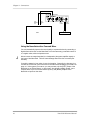
Basic Connections
The NanoVerb will work in many different applications, whether you are connecting
an instrument directly into it, or connecting it with a mixing console. Briefly described
here are the basic connections to get you up and running quickly. For more
information on connections, please refer to Chapter 2.
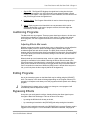
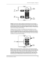
•
Mono In, Mono or Stereo Out. Connect a 1/4" phone cord to the [LEFT/MONO]
INPUT of the NanoVerb from a mono source. (The Left input will then feed both
inputs.) Connect another 1/4" phone cord from the [LEFT] OUTPUT of the
NanoVerb to an amplification system or mixer input. Additionally, you could
connect a second 1/4" phone cord to the [RIGHT] OUTPUT for use with a stereo
amplification system, or two mixer inputs.
•
Stereo. Connect two 1/4" phone cords to the [LEFT/MONO] & [RIGHT ] INPUTS
of the NanoVerb from a stereo source , and two 1/4" phone cords from the
[LEFT/MONO] & [RIGHT] OUTPUTS of the NanoVerb to a stereo amplification
system or two mixer inputs.
FROM INSTRUMENT OR EFFECTS SEND
LEFT INPUT
RIGHT INPUT
LEFT OUTPUT
RIGHT OUTPUT
If connecting to a mixing console’s aux sends/returns, you will want to turn the [MIX]
knob fully clockwise so that the NanoVerb outputs only wet (effected) signal.
Powering Up
After making your connections, turn on the system’s power using this procedure:
NanoVerb Reference Manual
7
Chapter 1 – Your First Session with the NanoVerb
¿ Before turning on the NanoVerb’s power, check the following items:
•
•
¡
Have all connections been made correctly?
Are the volume controls of the amplifier or mixer turned down?
Insert the Power jack into the [POWER] input on the rear panel of the NanoVerb
and plug the power adapter into an AC outlet.
Upon power-up, the Power On LED will illuminate.
¬ Turn on the power of the amplifier/mixer, and adjust the volume.
Setting Levels
Proper setting of the input and output levels is crucial in order to achieve the
maximum signal-to-noise ratio. As a good rule of thumb, it is usually best to set both
input and output level controls at 3/4 or 75% of full. This will decrease the possibility
of overload distortion and keep the amount of background noise to a minimum.
If the Signal LED on the NanoVerb begins to clip (turn red), turn down the Input level
or decrease the volume of the source (instrument, mixer send, etc.). If the
NanoVerb’s level is causing the mixer or amp to distort, turn the Output Level down.
For more detail on level setting, see page 25.
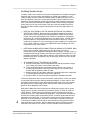
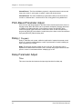
What’s on the Front Panel?
4
5
1
6
2
7
3
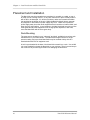
The NanoVerb’s front panel contains the following:
¨
Input. The Input level control sets the level going into the NanoVerb. This should
be adjusted so that the Signal LED (• ) is green when signal is going into the unit.
It controls both the Left and Right Input levels simultaneously.
¡
Mix. The Mix control adjusts the balance between the direct signal coming into
the input and the effects generated by the NanoVerb.
¬ Output. The Output level control sets the level going to the amplifier or mixer
from the NanoVerb.
÷ Power LED. The Power LED is illuminated whenever the NanoVerb's power
adapter is plugged in.
8
NanoVerb Reference Manual
Your First Session with the NanoVerb– Chapter 1
•
Signal LED. The Signal LED displays the signal level coming into the Input.
During normal operation, this LED should turn green whenever there is signal
coming into the inputs. If the signal level is at the maximum, this LED will turn red
and you will begin to hear the signal distort.
± Program Select. The Program Select Knob is used to choose the program you
wish to use.
£ Adjust. Each program on the NanoVerb has one parameter which can be
adjusted. Depending on the type of program selected, this knob might alter
reverb decay, chorus depth, etc.
Auditioning Programs
The NanoVerb has 16 programs. These programs have been chosen to be the most
useful effects available for a large variety of music styles. To audition the internal
effect programs, turn the Program Select knob to scroll through each of the 16
presets.
Adjusting Effects Mix Levels
Whether a program contains a single effect or two or three effects, you can adjust the
NanoVerb’s [MIX] control to obtain a desirable balance between the original,
uneffected signal and each effect’s output. The [MIX] Knob controls the balance
between the input signal and the effects generated by the NanoVerb. By turning [MIX]
to the right allows you to hear more effects; turning it to the left lets you hear more of
the source signal.
When hooked up to an instrument setup, such as a guitar amp, the Mix setting will
typically be somewhere in the middle, balancing the effects with the sound of the
source instrument. If the NanoVerb is connected to a mixing console’s Aux Send, the
[MIX] control should be set all the way to the right (effects only) so that the balance
can be controlled from the board. When the [MIX] control is turned all the way to the
left, you will only hear the direct signal (effects will be bypassed).
Editing Programs
Any of the internal programs on the NanoVerb may be editing using the [ADJUST]
knob. The function of this knob will change depending on the Program selected. For
example, it will adjust reverb decay on a Hall program and lezlie speed on the Rotary
program.
J
The Adjust knob is always active, so when you change to a new program it will
automatically read the Adjust knob setting.
Bypassing Effects
At any time you can bypass the effects, thereby allowing the direct signal to pass
through the NanoVerb unchanged. This can be done in two ways:
•
by turning the MIX knob all the way to the left,
•
by connecting a footswitch to the [BYPASS] jack and pressing the footswitch.
Each time the footswitch connected to the [BYPASS] jack is pressed, Bypass mode is
toggled on and off again. For more information about the Footswitch, see page 20.
NanoVerb Reference Manual
9
Chapter 1 – Your First Session with the NanoVerb
Placement and Installation
The NanoVerb may be mounted almost anywhere it's needed: on a table, on top of
an amp, next to a mixing console. In any case, make sure to place it safely where it
will not fall or be damaged. If it will be on furniture, make sure to attach the rubber
feet provided to the bottom of the unit. While the NanoVerb itself doesn't generate
any magnetic or hum fields, its power supply may do so. Make sure to place the
power supply away from other audio equipment that is sensitive to induced fields, and
away from the signal wiring. In rare instances, the NanoVerb itself may pick up noise
fields generated by other equipment such as large power amplifiers; in this case,
move the NanoVerb until the noise goes away.
Rack Mounting
The most secure mounting is on a "universal" rack shelf, available from various rack
manufacturers or your music dealer. The NanoVerb's height conforms to singlespace mounting, and up to three NanoVerbs may be mounted side-by-side in a
standard universal EIA 19" equipment rack.
A hole is pre-threaded in the base of the NanoVerb to attach it to a rack. Use an M5
x 6 screw (included) to fasten the NanoVerb to your rack tray. There is an end stop in
the screw hole to prevent longer screws from damaging the electronics.
10
NanoVerb Reference Manual
Connections – Chapter 2
CHAPTER 2
CONNECTIONS
AC Power Hookup
The NanoVerb comes with a power adapter suitable for the voltage of the country it is
shipped to (either 110 or 220V, 50 or 60 Hz).
To turn on the NanoVerb, plug the small end of the power adapter cord into
NanoVerb’s [POWER] socket and the male (plug) end into a source of AC power. It’s
good practice to not plug in the NanoVerb until all other cables are hooked up.
J
Alesis cannot be responsible for problems caused by using the NanoVerb or any
associated equipment with improper AC wiring.
Line Conditioners and Protectors
Although the NanoVerb is designed to tolerate typical voltage variations, in today’s
world the voltage coming from the AC line may contain spikes or transients that can
possibly stress your gear and, over time, cause a failure. There are three main ways
to protect against this, listed in ascending order of cost and complexity:
•
Line spike/surge protectors. Relatively inexpensive, these are designed to protect
against strong surges and spikes, acting somewhat like fuses in that they need to
be replaced if they’ve been hit by an extremely strong spike.
•
Line filters. These generally combine spike/surge protection with filters that
remove some line noise (dimmer hash, transients from other appliances, etc.).
•
Uninterruptible power supply (UPS). This is the most sophisticated option. A UPS
provides power even if the AC power line fails completely. Intended for computer
applications, a UPS allows you to complete an orderly shutdown of a computer
system in the event of a power outage, and the isolation it provides from the
power line minimizes all forms of interference—spikes, noise, etc.
Audio Connections
The connections between the NanoVerb and your studio are your music’s lifeline, so
use only high quality cables. These should be low-capacitance shielded cables with a
stranded (not solid) internal conductor and a low-resistance shield. Although quality
cables cost more, they do make a difference. Route cables to the NanoVerb correctly
by observing the following precautions:
•
Do not bundle audio cables with AC power cords.
•
Avoid running audio cables, or placing the NanoVerb itself, near sources of
electromagnetic interference such as transformers, monitors, computers, etc.
•
•
Never unplug a cable by pulling on the wire itself. Always unplug by firmly
grasping the body of the plug and pulling directly outward.
Do not place cables where they can be stepped on. Stepping on a cable may not
cause immediate damage, but it can compress the insulation between the center
conductor and shield (degrading performance), or reduce the cable’s reliability.
•
Avoid twisting the cable or having it make sharp, right angle turns.
NanoVerb Reference Manual
11
Chapter 2 – Connections
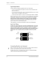
Typical Applications
The audio inputs and outputs are typically used in one of three ways:
•
from one or two effect/aux send outputs of a mixer, and out to the effect return
inputs of the mixer; or,
•
from a line-level instrument (like a guitar or keyboard with either a mono or stereo
output), and out to an amplifier or mixer input; or,
•
from the stereo buss outputs of a mixer to a mix-down tape machine or amplifier.
When used with a mono source, the NanoVerb is placed between the source and the
mixer/amplifier. Although the source may be mono, both the [LEFT] and [RIGHT]
outputs can be connected to the inputs of a mixer/amplifier if stereo processing
effects are desired. If using the effect sends of a mixer, you have the advantage of
sending any of the mixer’s input channels to the NanoVerb’s input(s), and have
control over the level of each channel being sent.
These applications are outlined and illustrated in detail on the following pages.
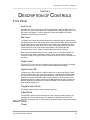
Input Jack Wiring
The NanoVerb’s [LEFT] INPUT jack is normalled to the [RIGHT] INPUT. This means
that if you only connect a single mono cable to the [LEFT] INPUT jack, it will also be
routed to the [RIGHT] INPUT. However, if anything is connected to the [RIGHT]
INPUT jack, this normalized connection will be broken; in this case the [LEFT] INPUT
jack will feed only the [LEFT] INPUT, and the [RIGHT] INPUT jack feeds only the
[RIGHT] INPUT. Also, the [RIGHT] INPUT jack is NOT normalled to the [LEFT]
INPUT.
Inputs
LEFT/CH 1
Outputs
LEFT/CH 1
RIGHT/CH 2
LEFT/CH 1
RIGHT/CH 2
LEFT/CH 1
RIGHT/CH 2
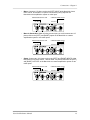
Connecting Directly to an Instrument
J
When connecting audio cables and/or turning power on and off, make sure that all
devices in your system have their volume controls turned down.
The NanoVerb has two 1/4” unbalanced inputs and two 1/4” unbalanced outputs.
These provide three different audio hookup options:
12
NanoVerb Reference Manual
Connections – Chapter 2
•
Mono. Connect a 1/4" phone cord to the [LEFT] INPUT of the NanoVerb from a
mono source, and another 1/4" phone cord from the [LEFT] output of the
NanoVerb to an amplification system or mixer input.
FROM INSTRUMENT OR EFFECTS SEND
LEFT OUTPUT
LEFT INPUT
•
Mono In, Stereo Out. While still using a mono input, you could connect two 1/4"
phone cords to the [LEFT] and [RIGHT] outputs of the NanoVerb to a stereo
amplification system or two mixer inputs.
FROM INSTRUMENT OR EFFECTS SEND
TO AMPLIFIER OR MIXING CONSOLE
LEFT OUTPUT
LEFT INPUT
•
TO AMPLIFIER OR MIXING CONSOLE
RIGHT OUTPUT
Stereo. Connect two 1/4" phone cords to the [LEFT] and [RIGHT] INPUTS of the
NanoVerb from a stereo source , and two other 1/4" phone cords from the [LEFT]
and [RIGHT] OUTPUTS of the NanoVerb to a stereo amplification system or two
mixer inputs.
FROM INSTRUMENT OR EFFECTS SEND
LEFT INPUT
NanoVerb Reference Manual
RIGHT INPUT
TO AMPLIFIER OR MIXING CONSOLE
LEFT OUTPUT
RIGHT OUTPUT
13
Chapter 2 – Connections
Interfacing to a Mixing Console
The NanoVerb handles mono or stereo sends at all system levels. The input circuitry
of the NanoVerb can easily handle professional +4 dBu levels (+20 dBu peaks), while
having enough input and output gain to interface with the low -10 dBV signal levels of
home recording systems.
The NanoVerb may be connected to a mixing console in several different ways. It can
be used to effect multiple channels at once by using the auxiliary send and return
controls of the mixer. Another method of interfacing is to connect the unit directly to
the insert send and return patch points of a single channel that is to be effected. Still
another way of interfacing the NanoVerb to a mixer or recording console would be inline between the output of your mixing console and the input of a tape deck or power
amplifier. This last setup would be used only if you wanted effects on the entire mix.
Using Aux Sends and Returns
Generally, mixing consoles provide two types of auxiliary sends: pre-fader sends for
creating a cue (headphone or monitor) mix, and post-fader sends for effects units.
Typically, if a mixer has more than two sends per channel (4, 6 or 8, perhaps), the
first two sends are reserved for the cue sends, while the remaining sends are used to
feed effects such as the NanoVerb. Connect the NanoVerb using post-fader sends,
so that when you fade a channel out, its effects will fade also.
Using a mixer’s aux sends allows each channel to have its own level control feeding
the aux output (and eventually the NanoVerb input). You can make a mix of any
channels you want to go to the effects by using the individual channels’ aux send
levels on the mixer. Most consoles also have aux master controls, which set the
overall level of each aux output.
But sending signal to the Nanoverb is only half the story. With a mixing console, the
output of the Nanoverb must be returned to the mixer and turned up in the mix before
you can hear it. Depending on the design of your mixer, you have two options for
returning the effected signal to the mix:
•
connecting to dedicated aux return inputs, or
•
connecting to channel inputs.
The former is good if your mixer provides dedicated inputs (called returns) for effect
devices like the NanoVerb. If your mixer does not have these, or you have already
used them all, consider connecting the NanoVerb to channel inputs (if there are any
remaining). This method gives you the added bonus of more panning options and EQ
on the effects.
No matter where you connect the output of the NanoVerb into the mixer, you are in
control of the balance between the mixer’s channel inputs (the uneffected signal
being routed to the aux sends and the Mix), and the effect returns coming from the
NanoVerb. The effect returns generally should only contain effected signal, and not
have any uneffected or "dry" signal mixed with it (since these two signals are blended
together at the mixer). Therefore, it is necessary to set the mix so that only effected
("wet") signal is present at the NanoVerb’s outputs. To do this, turn the Mix control all
the way to the right.
14
NanoVerb Reference Manual
Connections – Chapter 2
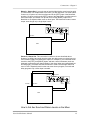
Mono In - Stereo Out. If you only want to feed the NanoVerb a mono input, but wish
to connect both of its outputs back to the mixer, you will need three 1/4" audio cables.
Connect a 1/4" phone cord from an effect send to the [LEFT] input of the NanoVerb,
another 1/4" phone cord from the [LEFT] output of the NanoVerb to an effect return or
other mixer input, and another 1/4" phone cord from the [RIGHT] output of the
NanoVerb to an adjacent effect return or mixer input. The Nanoverb creates a stereo
output, even though only a single input is used.
LEFT INPUT
LEFT
OUTPUT
AUX SEND 1
RIGHT
OUTPUT
AUX RETURNS OR INPUT CHANNELS
MIXER
Stereo In - Stereo Out. This connection is similar to the one described above.
However, by utilizing two sends from the mixer, we add one more cord and can now
send a stereo signal to the NanoVerb’s inputs. For example, if you connected sends
3 and 4 to the [LEFT] and [RIGHT] inputs, and had a stereo instrument (such as a
keyboard) connected to two channel inputs of the mixer (either one panned hard left
and hard right), you would send the left channel to send 3 and the right channel to
send 4. This is especially useful on the true stereo chorus program; on reverb and
delay programs only a mono input is needed.
LEFT INPUT
AUX SEND 1
RIGHT INPUT
LEFT
OUTPUT
AUX SEND 2
RIGHT
OUTPUT
AUX RETURNS OR INPUT CHANNELS
MIXER
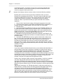
How to Set Aux Send and Return Levels on the Mixer
NanoVerb Reference Manual
15
Chapter 2 – Connections
In the above hookups, you must set correct levels on the mixer's individual Aux
Sends, Aux Masters, and Aux Return masters (as well as the NanoVerb's own
controls) to get good, clean, quiet results.
J
Improper level setting is the most common cause of noise and distortion problems.
By having the correct level at every point in the send/return chain, you avoid
distortion by overloading and avoid noise. The most common mistake with effect
units like the NanoVerb is to have too low a level at the input, then crank up the
output to get the effects level desired. This amplifies the noise and wastes
headroom. Here is a procedure that will give good results with most standard
equipment:
1. Set your mixer's input levels correctly, following the instructions for the mixer.
2. Turn up the mixer channels' AUX SEND and AUX MASTERS (if applicable) to a
nominal level (this is usually between "noon" and "3:00" on a rotary knob).
3. Play the source.
4. Turn up the NanoVerb's [INPUT] level until you see the [SIGNAL] LED turn red
on peaks; then reduce it slightly until the red doesn't flash. The ideal input level, for
optimum noise performance, is just below clipping. But if other instruments will be
added to the mix later, or levels are unpredictable (as in a live show), leave yourself
additional headroom by turning the input level down a bit more.
5. Depending on the input sensitivity of the mixer's channels or Aux Returns, the
[OUTPUT] knob of the NanoVerb should be set somewhere between "2:00" and fully
clockwise ("5:00").
6. Turn up the AUX RETURN level until you get the desired level of effect in the
mix. The one control in the chain that may need to be set to a low level is the Aux
Return (or channel) on the mixer itself. Here is where you should increase or
decrease the overall effect level in the mix, for best low-noise performance. If you
want "just a hint" of reverb, don't turn down the send to the Nanoverb; turn down the
Aux Return. Leave the input levels where they were set in step 4, unless you see the
[SIGNAL] LED flash.
Using Inserts
If your mixer features individual channel inserts, you can dedicate the NanoVerb to a
specific channel on the mixer. Insert jacks on the back of a mixer provide a way of
“inserting” external processing equipment into the signal path. The insert occurs after
the input amplifier, and before the channel fader; essentially it is the same as
connecting the source (instrument or microphone) into the NanoVerb before the mixer’s
channel input. However, some mixing console’s inserts come after the EQ section, and
may therefore be different from the original signal. If nothing is connected to the
channel’s Insert jack, the signal passes through with no effect.
Usually, insert connections require a special, stereo-splitting Y-cord to be connected
(one stereo plug provides both send and return while two mono plugs connect
separately to the effects unit’s input and output). These are known as TRS connectors
(tip-ring-sleeve). The tip of the stereo plug carries the send or output of the insert jack,
while the ring carries back the return. The sleeve represents a common ground for both
signals.
This involves connecting a 1/4" TRS (tip-ring-sleeve) Y-cable to the Insert jack of a
single channel on a mixing console. The other end of the cable (which splits into two,
1/4" mono connectors) are connected to the [LEFT] input and [LEFT] output,
respectively. If you do not hear any audio after making these connections, swap the
input and output cables at the NanoVerb, as these may be wired backwards. If the
cable is color-coded, usually the red jack represents the send (which connects to the
NanoVerb’s input) and black is the return (which connects to the output).
16
NanoVerb Reference Manual
Connections – Chapter 2
Once the proper connection has been made, you must set the desired "wet/dry"
balance using the NanoVerb's [MIX] control. The [INPUT] and [OUTPUT] controls of
the NanoVerb should be set for unity gain: the volume when the Insert jack is
plugged in the mixer should be approximately the same as when the NanoVerb is out
of the circuit.
MIXER
INSERT
LEFT INPUT
LEFT OUTPUT
Using Main Outputs
When you want to add effects to everything on the mixer, you can connect the
NanoVerb between the mixer’s outputs and the amplifier’s or tape machine’s inputs.
This is done by using two 1/4" mono cables to connect the Left and Right Main
Outputs of the mixing console to the [LEFT/MONO] and [RIGHT] inputs of the
NanoVerb. The [LEFT] and [RIGHT] outputs of the NanoVerb are then connected to a
stereo amplifier, or two input channels of another mixing console (for sub-mixing
applications).
NanoVerb Reference Manual
17
Chapter 2 – Connections
LEFT INPUT
LEFT
MASTER
OUT
RIGHT INPUT
RIGHT
MASTER
OUT
MIXER
LEFT
OUTPUT
RIGHT
OUTPUT
POWER AMP
Using the NanoVerb with a Powered Mixer
You can dramatically improve the sound quality of a powered mixer by connecting a
digital effects units such as the NanoVerb to it in the same way you would connect it
to a regular mixer, with one important note:
J
Never connect an output intended for a loudspeaker (the power amplifier output) to
the input of the NanoVerb. This will cause damage that will not be covered by the
warranty.
Consult the manual of your mixer for more information. Generally, the best way is to
connect the "Effect Out" jack of the mixer to the NanoVerb following the procedure on
page 14. If the system is not stereo, you may connect only the [LEFT] output of the
NanoVerb to an "Effect Return" or other input. You will get a slightly deeper, more
complex effect if you can connect both the [LEFT] and [RIGHT] outputs of the
NanoVerb to inputs on the mixer.
18
NanoVerb Reference Manual
Connections – Chapter 2
Avoiding Ground Loops
In today’s studio, where it seems every piece of equipment has complex routing and
computer logic, there are many opportunities for ground loop problems to occur.
These show up as hums, buzzes or sometimes radio reception and can occur if a
piece of equipment “sees” two or more different paths to ground. While there are
methods to virtually eliminate ground loops and stray radio frequency interference,
most of the professional methods are expensive and involve installing a separate
power source just for the sound system. Here are some easy helpful hints that a
professional studio installer might use to keep those stray hums and buzzes to a
minimum.
¿ KEEP ALL ELECTRONICS OF THE SOUND SYSTEM ON THE SAME AC
ELECTRICAL CIRCUIT. Most stray hums and buzzes happen as a result of
different parts of the sound system being plugged into outlets of different AC
circuits. If any noise generating devices such as air conditioners, refrigerators,
neon lights, etc., are already plugged into one of these circuits, you then have a
perfect condition for stray buzzes. Since most electronic devices of a sound
system don’t require a lot of current (except for power amplifiers), it’s usually safe
to run a multi-outlet box or two from a SINGLE wall outlet and plug in all of the
components of your system there.
¡
KEEP AUDIO WIRING AS FAR AWAY FROM AC WIRING AS POSSIBLE. Many
hums come from audio cabling being too near AC wiring or the power
transformers used by equipment requiring an external supply. If a hum occurs, try
moving the audio wiring around to see if the hum ceases or diminishes. If it’s not
possible to separate the audio and AC wiring in some instances, make sure that
the audio wires don’t run parallel to any AC wire (they should only cross at right
angles, if possible).
¬ TO ELIMINATE HUM IF THE ABOVE HAS FAILED:
A) Disconnect the power from all outboard devices and tape machines except
for the mixer and control room monitor power amp.
B) Plug in each tape machine and outboard effects device one at a time. If
possible, flip the polarity of the plug of each device (turn it around in the
socket) until the quietest position is found.
C) Make sure that all of the audio cables are in good working order. Cables with
a detached ground wire will cause a very loud hum!!
D) Keep all cables as short as possible, especially in unbalanced circuits.
If the basic experiments don’t uncover the source of the problem, consult your dealer
or technician trained in proper studio grounding techniques. In some cases, a “star
grounding” scheme must be used, with the mixer at the center of the star providing
the shield ground on telescoping shields, which do NOT connect to the chassis
ground of other equipment in the system.
J
Note that the NanoVerb, with its external low-voltage power supply, has no power
supply ground. Its power is transformer isolated for safety, so it has no need for a
"safety ground". Signal ground is connected to chassis ground at the input and
output jacks (as it is in most unbalanced equipment). If the NanoVerb is attached to
a metal rack mounting shelf, the assembly shares a common ground with the other
equipment in the same rack. In some cases (such as a star ground scheme), you
may wish to use nonconductive rack rails or rack isolators to avoid ground loops.
To avoid the possibility of electric shock, never defeat the safety ground found on
other equipment in the system. When in doubt about proper electrical grounding
schemes or the power to your system, consult a qualified, licensed electrician.
NanoVerb Reference Manual
19
Chapter 2 – Connections
Footswitch
On the rear panel you will find a footswitch jack labeled [BYPASS]. This is a mono
jack with connections for a normal momentary footswitch. The footswitch must be
plugged in before the NanoVerb has its power turned on.
You should not use the footswitch supplied with a guitar amplifier, as these are
typically latching type footswitches. You can tell a latching footswitch from an
unlatched type when it takes two presses to enable any of the functions (Bypass,
etc.). Also, these footswitches usually “click” when stepped on. Use only Momentary
(non-latching) footswitches with the NanoVerb.
Pressing the footswitch will toggle Bypass mode on and off. When Bypass mode is
activated, the effects will mute but the direct signal will continue going through the
unit. Bypass turns off any effects going to the output, and is useful for turning off
delay for a certain part of a song, for example.
20
NanoVerb Reference Manual
Overview of Programs – Chapter 3
CHAPTER 3
OVERVIEW OF PROGRAMS
Reverb Effects
Reverb is made up of a large number of distinct echoes, called reflections. In a
natural acoustic space, each reflection’s amplitude and brightness decays over time.
This decaying action is influenced by the room size, the location of the sound source
in the room, the hardness of the walls, and many other factors. The NanoVerb offers
the following types of reverberation:
Concert Hall (3 Programs)
This is a simulation of a large concert hall. Halls tend to be large rooms with lots of
reflective surfaces, where sounds can swim around, changing timbre over time. This
is a classic reverb which sounds good on just about anything. Try it on vocals, drums,
acoustic, electric, or orchestral instruments.
Hall 1 - This is a large bright hall program. It works well for almost anything, try it on
drums, guitars or vocals.
Hall 2 - This is a warmer hall program. It especially adds depth and character to
acoustic guitars and pianos with it's decay set long.
Hall 3 - The third program is a medium hall with 12ms of predelay before the reverb
starts. It sounds great on big rock snares, but try it on vocals and electric guitar too.
Real Room (3 Programs)
This algorithm gives you the sound of a medium size studio room. This algorithm
uses a lot of processing power for a rich sound and smooth decay. It has a punchier,
bigger sound than a hall reverb, which makes it good for rock and dance music. The
attack is also more reflective. It sounds good on drums, keyboards and guitars.
Room 1- This hardwood studio room has a lot of early reflection slap for big drum
sounds. It also works well for acoustic instruments, especially with the decay turned
up.
Room 2- This program is perfect for adding a little ambiance to a dry track. Try it on
antiseptic synth sounds or on dry, unplugged mixes with the decay set short.
Room 3- Ideal for acoustic guitars and classical instruments, this program emulates a
warmer studio room.
Plate Reverb (3 Programs)
This is a simulation of a classic echo plate, a 4' by 8' suspended sheet of metal with
transducers at either end used to produce reverb. Popular in the 1970’s, it is still
prized for its transparent sound, particularly on vocals and guitars. It works well for a
lush lead vocal, piano, or guitar, especially when looking for a classic rock and roll
sound.
Plate 1- The first program is a classic bright vocal plate for pristine lead and
background vocals.
Plate 2- A warmer variation of the previous program, great for adding sustain on
acoustic guitar and strings.
Plate 3- This program is a more realistic simulation of a vintage tube plate reverb. It
has very little bottom end, which makes it great for snappy snares and skinny guitars.
NanoVerb Reference Manual
21
Chapter 3 – Overview of Programs
Nonlinear (1 Program)
In the mid '80s, a certain British producer/engineer (who shall remain anonymous)
discovered a clever way of creating a huge drum sound. He would place the drum set
in a large, reverberant room, mic the room and chop off the end of the reverb tail with
a noise gate. When this sound caught on, digital reverbs began to be released with a
"Nonlinear" program, which simulated this effect. In the end their simulation became
more widely used than the effect it was trying to emulate, and the non linear reverb
earned it's place in effects history.
Non Linear- This is a classic example of the mid-80's "Nonlin" gate program. It is
most commonly used on snares and toms, but can also spice up brass stabs and
percussion.
Reverb Parameter Adjust
Decay
The reverb decay determines how long the reverb will sound before it dies away.
Turning up the reverb decay will have the effect of increasing the room's size.
Generally, classical, jazz, and ballad styles will use longer decay times than uptempo rock or dance music.
Pitch Based Effects (5 Programs)
Pitch based effects alter the pitch and delay of a signal in various ways to produce
“layered” timbres that are more complex than the original signal. Some of these
effects are achieved by splitting the signal into at least two parts, effecting the pitch of
one of the parts, then mixing them back together. This eventual mixing is essential
since the overall sound of the effect is achieved by the difference between the dry,
uneffected signal and the effects signal. Therefore, when using chorus or flange, it’s
best to keep the mix of effected and direct signal at equal strength. This could mean
setting the [MIX] control at 50% of the NanoVerb on an instrument setup, or raising
the effect return on a mixer.
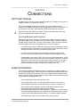
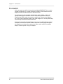
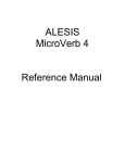
Chorus- The chorus effect is achieved by splitting the signal into four parts with a dry
signal and a separate detuning section for both left and right channels. The detuning
is further effected by being modulated by an LFO (low frequency oscillator) which
causes the detuning to vary. The NanoVerb’s chorus has individual LFOs controlling
the left and right sides, set at different rates. This effect, called true stereo chorus,
often has a wider stereo image than regular stereo chorus effects. When the Rate is
changed on a true stereo chorus, the chorus rate difference between the left and right
sides is maintained. Note: This chorus processes the left and right sides individually,
so any stereo imaging will be maintained.
22
NanoVerb Reference Manual
Overview of Programs – Chapter 3
DRY SIGNAL
FEEDBACK
LEFT
DRY
SIGNAL
DELAY
LEFT
CHORUSED
OUTPUT
DETUNE
LFO
LFO
RIGHT
DRY
SIGNAL
DELAY
DETUNE
FEEDBACK
RIGHT
CHORUSED
OUTPUT
DRY SIGNAL
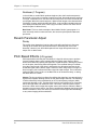
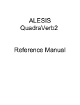
Flange- First used in the 1960s, “flanging” was achieved by the use of two tape
recorders that would record and play back the same program in synchronization. By
slowing down one tape machine, and then letting it catch up with the other, different
phase cancellations would occur at different frequencies. Since the slowing down of
the tape machines was done by hand pressure against the flanges of the tape supply
reels, the term “flanging” came into being.
Flanging is similar to chorusing , but modulates the delayed signal over a much
shorter delay range (typically 0-12 ms). This produces a “jet airplane”-like sound. In
the case of the NanoVerb's flange, the signal is split into four parts with a stereo dry
signal and a separate delay section for both left and right channels with one channel
flanging up while the other channel flanges down. Once again, this causes the effect
to become more pronounced and dramatic.
DRY SI G N AL
FEEDBA C K
LEFT
FLA N G ED
O UTPUT
DELA Y
DRY
SI G N AL
LFO
DELA Y
FEEDBA C K
RI G HT
FLA N G ED
O UTPUT
DRY SI G N AL
Rotary- The Rotary effect emulates a rotating speaker. This effect was extremely
popular during the 1960s and was achieved by mechanically rotating the speakers to
produce complex timbral changes. The lezlie speaker system is most often used with
tone-wheel organs, but is occasionally used for guitar amplification as well. When
changing the speed between fast and slow, the effect will slowly ramp to the new
speed rather than change abruptly, just as the original would do. Note: When using
the Rotary program, the Mix parameter should be turned all the way to the right.
NanoVerb Reference Manual
23
Chapter 3 – Overview of Programs
Chorus/Room 1- The first multieffects program is a layered true stereo chorus and
large room reverb. It works great on guitars, synths and electric pianos.
Chorus/Room 2- The other multieffects program adds a delay to the chorus/room
sound for a different flavor. It works well for slow, funky guitars or big ballad solos.
Pitch-Based Parameter Adjust
On the chorus and flange programs, the Rate control sets the speed of the chorus or
flanging sweep. When the chorus rate is increased, the depth is similarly decreased
to maintain a constant pitch shift. On the Rotary program, the [ADJUST] knob
controls the speed of the Lezlie motor, either fast or slow. On the Chorus/Room 1
program the [ADJUST] knob edits the reverb decay time, where on the Chorus/Room
2 program [ADJUST] edits the delay time.
Delay (1 Program)
Delay is a discrete echo repeat, unlike the rapid wash of repeats that create reverb
effects. It is useful for adding depth to a track or performance if reverb is adding too
much coloration to the sound.
Delay- This program provides a delay of up to 1270 ms. The delay time can be
adjusted in 10 millisecond increments. This is a useful utility program which can add
space to vocals or instruments without "muddying up" a mix.
Delay Parameter Adjust
Time
This control sets the time between the input signal and the first delay tap.
24
NanoVerb Reference Manual
Description of Controls – Chapter 4
CHAPTER 4
DESCRIPTION OF CONTROLS
Front Panel
Input Level
The [INPUT] Level controls the level of the signal being fed into the NanoVerb. The
NanoVerb can operate with signal levels anywhere from +4dBu pro audio gear to -20
dBV guitar level signals. To set the input level, watch the [SIGNAL] LED while
adjusting the [INPUT] level (see below).
Mix Level
The [MIX] Level controls the balance between the uneffected signal coming through
the inputs and the effects being generated by the NanoVerb. When [MIX] is turned all
the way to the left, the input signal will be sent straight to the output with no effects
added. When [MIX] is turned all the way to right, only the effects will be sent to the
outputs with none of the original input signal mixed in. By keeping the Mix
somewhere in the center, a blend of dry and wet signal can be achieved.
With a typical instrument setup (use with a guitar amp, etc.) the Mix is usually set
around 12 o’clock. When used with a mixing console, the Mix control should be
turned all the way to the right (full wet) so that the effects mix can be controlled from
the mixer.
Output Level
The [OUTPUT] Level controls the volume of the signal from the outputs. The typical
level for this control is 75%, but it can be raised or lowered as necessary.
Signal Level LED
This dual-color LED monitors the signal strength of the unprocessed inputs, and is
used in much the same way as the level meters on a standard tape recorder. When
the LED turns red, the input signal will be distorted so the [INPUT] level should be
backed off. If the green [SIGNAL] LED is barely coming on, the input signal is not
high enough and the resulting sound from the NanoVerb may be noisy. Ideally, the
[INPUT] signal level should be set so that the [SIGNAL] LED is solid green when
audio is being played into it.
Program Select Knob
The Program Select Knob is used to change programs.
Adjust Knob
The [ADJUST] Knob is used to edit aspects of the currently selected program. For
example, on a Concert Hall program, the Adjust knob edits Reverb Decay Time.
[ADJUST] is always active, so newly selected programs always read the knob setting.
Rear Panel
Power
NanoVerb Reference Manual
25
Chapter 4 – Description of Controls
This is a plug for connecting the Alesis Model P3 9VAC power supply (supplied). The
power supply included with the NanoVerb is compatible with the electrical
requirements of the country of purchase, and should be connected to the proper
electrical outlet. (In the USA, this is 120VAC.) The correct power supply must be
used AT ALL TIMES. Any other power supply might create a fire risk and/or
permanently damage your unit. This damage would NOT be covered under your
warranty.
Bypass
This is a 1/4" phone jack which connects to a momentary (not latching) footswitch,
either normally-open or normally-closed. When the Footswitch is pressed, the
NanoVerb will stop producing effects and only the dry signal will pass through the
unit. If the Footswitch is pressed again, effects output will continue.
Input (Left/Mono & Right)
These are 1/4" unbalanced phone jacks which connect to sources such as the effects
sends of mixing consoles. They may be used with nominal input levels from -20dBV
(guitar level) to +4dBu. For mono applications, use the [LEFT/MONO] input.
The [LEFT/MONO] input jack is normalled to the [RIGHT] jack. This means that when
nothing is plugged into the [RIGHT] input jack, the signal present at the
[LEFT/MONO] input is routed to the [RIGHT] as well.
Output (Left & Right)
These are 1/4" unbalanced phone jacks which connect to devices such as the effects
returns on a mixing console or power amplifier inputs. For mono applications, use the
[LEFT] output.
26
NanoVerb Reference Manual
Troubleshooting – Chapter 5
CHAPTER 5
TROUBLESHOOTING
Troubleshooting Index
If you experience problems while operating the NanoVerb, please use the following
table to locate possible causes and solutions before contacting Alesis Product
Support for assistance.
Symptom
Cause
The Power LED does not
No power.
light when the unit is
powered on.
Sound is distorted, Red
Input level is too high.
“Input” LED is lit
Sound is excessively noisy, Input level is too low
Green “Input” LED barely
lit.
Output level is too low
and Aux Return on mixer
is up full.
No audio is heard.
Bypass function is on
with Mix turned 100%
wet.
Output level is too low.
Hum or noise from output.
Ground loop, unshielded
cables.
Unit does not respond to
front panel controls.
Unknown software
conflict, cosmic rays, or
static electricity.
Solution
Check that the power cable
is plugged in properly.
Turn down the Input Level
control.
Turn up the Input Level
control.
Turn Output up and reduce
Aux Return level on mixer.
Turn the Mix control to the
left or press the Bypass
Footswitch.
Turn the Output control to
the right.
Try plugging the unit into
another power jack or
different audio cables.
Power down and power up
again.
Maintenance/Service
Cleaning
Disconnect the AC cord, then use a damp cloth to clean the NanoVerb’s metal and
plastic surfaces. For heavy dirt, use a non-abrasive household cleaner such as
Formula 409 or Fantastik. DO NOT SPRAY THE CLEANER DIRECTLY ONTO THE
FRONT OF THE UNIT AS IT MAY DESTROY THE LUBRICANTS USED IN THE
SWITCHES AND CONTROLS! Spray onto a cloth, then use cloth to clean the unit.
Refer All Servicing to Alesis
We believe that the NanoVerb is one of the most reliable multieffects processors that
can be made using current technology, and should provide years of trouble-free use.
However, should problems occur, DO NOT attempt to service the unit yourself.
Service on this product should be performed only by qualified technicians. NO USER SERVICEABLE PARTS INSIDE.
Obtaining Repair Service
Before contacting Alesis, check over all your connections, and make sure you’ve read
the manual.
NanoVerb Reference Manual
27
Chapter 5 – Troubleshooting
Customers in the USA and Canada: If the problem persists, call Alesis USA at 1310-841-2272 and request the Product Support department. Talk the problem over
with one of our technicians; if necessary, you will be given a return order (RO)
number and instructions on how to return the unit. All units must be shipped prepaid
and COD shipments will not be accepted.
For prompt service, indicate the RO number on the shipping label. Units without an
RO will not be accepted. If you do not have the original packing, ship the NanoVerb in
a sturdy carton, with shock-absorbing materials such as styrofoam pellets (the kind
without CFCs, please) or “bubble-pack” surrounding the unit. Shipping damage
caused by inadequate packing is not covered by the Alesis warranty.
Tape a note to the top of the unit describing the problem, include your name and a
phone number where Alesis can contact you if necessary, as well as instructions on
where you want the product returned. Alesis will pay for standard one-way shipping
back to you on any repair covered under the terms of this warranty. Next day service
is available for a surcharge.
Field repairs are not normally authorized during the warranty period, and repair
attempts by unqualified personnel may invalidate the warranty.
Service address for customers in the USA:
Alesis Product Support
3630 Holdrege Avenue
Los Angeles, CA 90016
Customers outside the USA and Canada:
Contact your local Alesis distributor for any warranty assistance. The Alesis Limited
Warranty applies only to products sold to users in the USA and Canada. Customers
outside of the USA and Canada are not covered by this Limited Warranty and may or
may not be covered by an independent distributor warranty in the country of sale. Do
not return products to the factory unless you have been given specific instructions to
do so.
28
NanoVerb Reference Manual
Specifications
SPECIFICATIONS
Electrical
Frequency Response:
Dynamic Range:
Distortion:
Crosstalk:
±1dB from 20Hz to 20 kHz
>90dB "A" wtg., 20 Hz-22kHz
<0.009% @ 1kHz, nominal level (-12 dBfs)
<0.005% @ peak level
<90dB below full scale
Input
Number of Channels:
Format:
Nominal Level:
Maximum Level:
Impedance:
2
1/4" unbalanced
-10 dBV, adjustable to +4 dBu
+10 dBV
1MW/channel stereo, 500kW/channel mono
A/D - D/A Conversions
A/D converter:
D/A converter:
18 bit Sigma-Delta, 128 times oversampling
18 bit Sigma-Delta, 8 times oversampling
Output
Number of Channels:
Format:
Maximum Level:
Nominal Level
Output Impedance:
2
1/4" unbalanced
+17.5 dBu
-20 dBV or +4dBu, front- panel adjustable
500 ohms
Front Panel
Controls
Indicators
INPUT
MIX
OUTPUT
PROGRAM
ADJUST
Power LED, Signal Present dual-color LED
Rear Panel
Input (LEFT/MONO, RIGHT)
Output (LEFT, RIGHT)
BYPASS
Power
1/4" 2-conductor
1/4" 2-conductor
1/4" 2-conductor (accepts normally open/closed
momentary footswitches, such as Alesis PD)
9 Volt Power Transformer (Alesis P3)
Processing and Memory
Processor Speed:
Internal processing resolution:
Factory Preset Programs (ROM):
Delay memory:
Reverb effects:
Delay effects:
Pitch effects:
NanoVerb Reference Manual
3 MIPs (million instructions per second)
24 bit accumulator
16
1270 milliseconds
Concert Hall, Real Room, Plate Reverb,
Nonlinear
Mono Delay
True Stereo Chorus, Stereo Flange,
Chorus/Room, Rotary
29