1
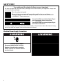
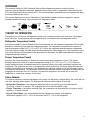
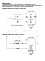
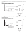
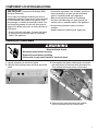
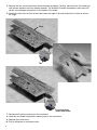
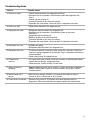
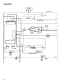
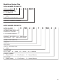
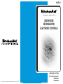
KAR-10
TECHNICAL EDUCATION
SIDE-BY-SIDE
REFRIGERATOR
ELECTRONIC CONTROLS
JOB AID 4317324
© 2001. All rights reserved.
® Registered Trademark/TM Trademark of KitchenAid, U.S.A.
1/01
Printed in U.S.A.
Introductory models:
KSRA22FK
KSRA25FK
TABLE OF CONTENTS
SAFETY FIRST ....................................................................................................................................................2
Electrical Power Supply Connections.............................................................................................................2
OVERVIEW ..........................................................................................................................................................3
THEORY OF OPERATION ..................................................................................................................................3
Refrigerator Temperature Control...................................................................................................................3
Freezer Temperature Control .........................................................................................................................3
Failure Defaults ..............................................................................................................................................3
Baffle Operation..............................................................................................................................................4
Adaptive Defrost Control ................................................................................................................................6
Pulsed Defrost ................................................................................................................................................6
Evaporator Fan Delay ...................................................................................................................................6
Over Temperature Alarm ...............................................................................................................................6
Water Filter Indicator .....................................................................................................................................6
Max Cool .......................................................................................................................................................6
COMPONENT LOCATION AND ACCESS..........................................................................................................7
Replacing the Control Board ..........................................................................................................................7
Replacing the Air Baffle ..................................................................................................................................9
Replacing the Thermistors............................................................................................................................10
DIAGNOSIS........................................................................................................................................................11
Pre-Diagnostics Checks ...............................................................................................................................11
Diagnostics Mode .........................................................................................................................................11
Diagnostics Chart .........................................................................................................................................12
Thermistor Resistance Chart........................................................................................................................12
Troubleshooting Guide .................................................................................................................................13
TECH TIPS.........................................................................................................................................................14
Wiring Diagram.............................................................................................................................................14
Model/Serial Number Plate ..........................................................................................................................15
For technical assistance while at the customer's home, call the Technical Assistance
Line: 1-800-253-2870.
Have your store number ready to identify you as an Authorized Servicer.
For product specifications, and warranty information, call 1-800-422-1230.
We recommend that you only use factory specified replacement parts. Factory specified replacement parts will fit right
and work right because they are made with the same precision used to build every new KITCHENAID® appliance.
Whirlpool Corporation assumes no responsibility for any repairs made on our products by anyone other
than Authorized Service Technicians.
1
SAFETY FIRST
Your safety and the safety of others are very important.
We have provided many important safety messages in this manual and on your appliance. Always read
and obey all safety messages.
This is the safety alert symbol.
This symbol alerts you to potential hazards that can kill or hurt you and others.
All safety messages will follow the safety alert symbol and either the word “DANGER”
or “WARNING.” These words mean:
You can be killed or seriously injured if you
don't immediately follow instructions.
You can be killed or seriously injured if you
don't follow instructions.
All safety messages will tell you what the potential hazard is, tell you how to reduce the chance of injury,
and tell you what can happen if the instructions are not followed.
Electrical Power Supply Connections
w WARNING
w WARNING
Electrical Shock Hazard
Electrical Shock Hazard
Plug into a grounded 3 prong outlet.
Do not remove ground prong.
Do not use an adapter.
Do not use an extension cord.
Failure to follow these instructions can result
in death, fire, or electrical shock.
Disconnect power before servicing.
Replace all panels before operating.
Failure to do so can result in death or
electrical shock.
2
OVERVIEW
The electronic control for 2001 KitchenAid Side-by-Side refrigerators combines several functions
previously used in separate components: Adaptive Defrost Control (ADC), Independent Temperature Control
(ITC) and Water Filter Indicator Control (WFI). Two new technologies, pulsed defrost and evaporator fan delay,
are incorporated into this control.
The numeric display can be set for Fahrenheit or Celsius and will display customer temperature settings.
Available features will include: Max Cool and Over Temperature Alarm.
THEORY OF OPERATION
The control runs a 13 second self-diagnostic routine prior to starting a cooling cycle every time it is plugged
into a wall outlet. The compressor will start approximately 10 seconds into the self-diagnostic routine.
Refrigerator Temperature Control
A motorized air baffle is used to regulate air flow from the freezer into the refrigerator compartment. The air baffle
operation is controlled by input from the refrigerator thermistor. The refrigerator control allows the customer to
select a temperature range of 33°F (1°C) to 41°F (9°C). When the refrigerator thermistor senses a temperature
above the customer setting, the baffle opens and the evaporator fan motor begins to run. The compressor may or
may not be running at this time based on the temperature in the freezer. The baffle closes when the refrigerator
temperature setting is reached.
Freezer Temperature Control
Input from the freezer thermistor is used by the control to determine compressor run time. The freezer
thermistor allows the customer to select a temperature setting of -5°F (-21°C) to +5°F (-15°C). When the
freezer thermistor senses a temperature above the customer setting, the control immediately energizes the
compressor. The evaporator fan motor is energized after a 40-second delay. This delay allows the evaporator
to begin to cool before air is circulated. If the evaporator fan is already running to cool the refrigerator section,
it will continue without delay. The compressor turns off when the proper freezer temperature is reached, but the
evaporator fan continues to run for 2 minutes. To protect the compressor, the control will not allow the
compressor to restart for a minimum of 6 minutes.
Failure Defaults
To provide a measure of customer satisfaction in the event of a thermistor or keypad failure, the control will use
one of the following default modes. The default mode continues until the failure is corrected.
• Refrigerator Thermistor: If the refrigerator thermistor fails, the control will cycle the baffle open for
10 minutes, closed for 10 minutes. The evaporator fan will run when the baffle is open.
• Freezer Thermistor: If the freezer thermistor fails, the compressor and evaporator fan will cycle on and off
together in 15-minute intervals.
• Keypad Failure Mode: If the control detects that the keypad is not working, it will default to
temperature regulation of 0°F (-18°C) for the freezer and 37°F (3°C) in the refrigerator.
3
Baffle Operation
The baffle assembly consists of a 120vac motor, a baffle door and a feedback switch. The switch
provides a sensing circuit to the control to let it know the position of the baffle door. When the refrigerator thermistor
senses a temperature above the customer setting, the motor runs to open the baffle door.
Refrigerator thermistor calling for cooling - Baffle opening
N
L1
ELECTRONIC CONTROL
P1-1
AIR BAFFLE ASSEMBLY
Y/R
BK
BAFFLE
TRIAC
6
4
OR/BK
P1-3
P2-1
WH
5
EVAP. MOTOR
TRIAC
EVAP. FAN MOTOR
BK
WH/BK
P2-3
P4-3
P4-4
BAFFLE MOTOR AND EVAPORATOR FAN RUNNING
BAFFLE OPENING
When the baffle door is fully open, the switch closes sending 120vac out pin 4 (Y/R wire) on the baffle door
assembly to pin P1-1 on the control. When the control senses 120vac at P1-1, the motor stops with the door fully
open.
Refrigerator thermistor calling for cooling - Baffle open
N
L1
ELECTRONIC CONTROL
P1-1
AIR BAFFLE ASSEMBLY
Y/R
BK
6
4
OR/BK
P1-3
P2-1
5
EVAP. MOTOR
TRIAC
EVAP. FAN MOTOR
BK
WH/BK
P2-3
BAFFLE MOTOR OFF, DOOR FULLY OPEN
EVAPORATOR FAN MOTOR RUNNING
4
P4-3
P4-4
WH
When the refrigerator thermistor reaches the cutout temperature, the control energizes the baffle motor to close
the door.
Refrigerator thermistor satisfied - Baffle closing
N
L1
ELECTRONIC CONTROL
P1-1
AIR BAFFLE ASSEMBLY
Y/R
BK
BAFFLE
TRIAC
6
4
OR/BK
P1-3
P2-1
WH
5
MOTOR RUNNING AND DOOR CLOSING
P4-3
P4-4
When the baffle is fully closed, the switch opens interrupting power to P1-1. This signals the control to stop the baffle
motor with the door fully closed.
Refrigerator thermistor satisfied - Baffle closed
N
L1
ELECTRONIC CONTROL
P1-1
AIR BAFFLE ASSEMBLY
Y/R
BK
4
6
OR/BK
P1-3
P2-1
WH
5
MOTOR OFF AND DOOR FULLY CLOSED
P4-3
P4-4
5
Adaptive Defrost Control
The Adaptive Defrost Control allows the unit to enter a defrost mode only when it is needed. When powered up
for the first time, the control will initiate a defrost cycle after 8 hours of compressor run time. By monitoring the
duration of defrost heating time and compressor run time, the control will continuously adapt the time between
defrosts to optimize efficiency. Time between defrost periods will vary from 8 to 100 hours.
Pulsed Defrost
For the first 5 minutes of defrost, the heater is on continuously. It then cycles off for 1 minute and back on for
2 minutes. It continues to cycle at this ratio until the bi-metal opens or 25 minutes have elapsed. At this point
heat is discontinued, and a 3-minute “drip time” begins. This allows the water to drain before the refrigerator
returns to the cooling mode. Maximum defrost time (heat time plus drip time) is 28 minutes.
Evaporator Fan Delay
The evaporator fan motor will start 40 seconds after the compressor is energized and continue for 2 minutes
when it cycles off.
After defrost, fan delay prevents unnecessary movement of warm moist air through the refrigerator by chilling
the evaporator prior to starting the fan. Immediately after the defrost drip time the compressor starts, but the
evaporator fan is delayed by 4 minutes 15 seconds. The baffle will be closed during defrost and remain closed
for 10 minutes after defrost.
Over Temperature Alarm
The Over Temperature Alarm sounds and the indicator light flashes when either the refrigerator
temperature exceeds 48°F (9°C) or the freezer temperature exceeds 15°F (-9°C) for over 1.5
hours. The Alarm stops if the temperature(s) return to normal, but the indicator continues to flash.
Pushing the Over Temperature Reset button turns off the Alarm and/or Indicator.
NOTE: When the refrigerator is first started, it may take longer than 1.5 hours to reach the customer selected
settings. It is normal for the Over Temperature Alarm to sound/flash.
Water Filter Indicator
The Water Filter Indicator displays the condition of the filter. Both dispenser usage and
time elapsed are monitored to determine the filter’s status. A green light indicates a good
filter, yellow means order a replacement filter and red means replace the filter. To reset
the counter, press and hold the reset button for two seconds.
LED color
Description
Gallons
Time (days)
Green
Good Filter
0-449
0-327
Yellow
Order Filter
450-499
328-364
Red
Change Filter
500+
365+
Max Cool
When selected, Max Cool changes the refrigerator setting to 34°F (1°C) and the freezer to –10°F
(-23°C) for 24 hours. The control will return to the previous user setting after 24 hours or at any
time the customer changes the settings.
6
COMPONENT LOCATION AND ACCESS
IMPORTANT: Electrostatic Discharge (ESD)
Sensitive Electronics
Do not open the package containing the service
replacement electronic board until it is time to install
it. ESD conditions are present everywhere. ESD
may damage or weaken the electronic boards. The
new board may appear to work well after repair is
finished, but failure may occur at a later date due to
ESD stress.
• Use an anti-static wrist strap. Connect wrist strap
to green ground connection point or unpainted
metal in the appliance.
• If anti-static wrist strap is not available, touch your
finger repeatedly to a green ground connection
point or unpainted metal in the appliance.
• Before removing the board from its package,
touch the anti-static bag to a green ground connection point or unpainted metal in the appliance.
• Avoid touching electronic parts or terminal
contacts.
• Handle electronic boards by their edges only.
Replacing the Control Board
wWARNING
Electrical Shock Hazard
Disconnect power before servicing.
Replace all panels before operating.
Failure to do so can result in death or electrical shock.
1. Unplug refrigerator or disconnect power.
2. Remove the mounting screws and drop the control
panel.
3. Press against the plastic retaining clips to release
the main portion of the board from the control box.
Then release the narrow portion of the board.
4. Disconnect the wire connectors and carefully
remove the board from the control panel.
7
5. Remove the new control board from the electrostatic packaging. Carefully, bend the front of the board up
until the tabs between the circuit boards separate. The boards will remain connected by trace wires. Be
careful not to damage components on the topside of the board.
6. Position the tabs from the front of the board under the edge of the main board until it is bent to about a
40° angle.
Front
Tab
Front board tab
under main board
7. Reconnect the wiring connectors to the new board.
8. Install the new board under plastic retaining clips on the control box.
9. Replace the control panel.
10. Plug in refrigerator or reconnect power.
8
Replacing the Air Baffle
w WARNING
Style 1 Ice-in-the-door Ice Maker
Air Chute
Air Scoop
Electrical Shock Hazard
Disconnect power before servicing.
Replace all panels before operating.
Failure to do so can result in death or
electrical shock.
1. Unplug refrigerator or disconnect power.
2. Remove the mounting screw and wire channel
from the top of the refrigerator compartment.
Style 2 Standard Ice Maker
3. Remove the mounting screw and air baffle cover.
6. Release the air baffle retaining clips from the
freezer compartment and push the air baffle
toward the refrigerator compartment.
4. Locate the air chute in the top of the freezer
compartment.
NOTE: For models in which the ice maker is
turned for ice in the door, pull the ice maker
forward and remove it from the product.
5. Remove the air chute mounting screw and cover.
Style 1 - Remove the air chute. Then remove the
air scoop from the baffle.
Style 2 - Remove the air chute from the baffle.
9
7. Pull the air baffle assembly into the refrigerator
compartment and disconnect the wiring connector
from the baffle motor.
2. Remove the wiring channel from the top of the
refrigerator compartment.
3. Remove the air baffle cover and disconnect the
thermistor lead connector.
8. Reinstall the baffle assembly in the reverse order.
9. Plug in refrigerator or reconnect power.
Replacing the Thermistors
w WARNING
4. Remove the lead from the strain relief.
Electrical Shock Hazard
Disconnect power before servicing.
Replace all panels before operating.
Failure to do so can result in death or
electrical shock.
Refrigerator Compartment Thermistor:
1. Unplug refrigerator or disconnect power.
5. Attach the new lead connector and place the new
lead in the strain relief.
6. Replace the baffle cover and wiring channel.
7. Plug in refrigerator or reconnect power.
10
Freezer Compartment Thermistor:
1. Unplug refrigerator or disconnect power.
2. Remove the air baffle assembly. See the
“Removing the Air Baffle” section.
3. Remove the tape from the freezer thermistor lead.
4. Pull freezer thermistor through the refrigerator
compartment wall and disconnect the lead
connector.
5. Connect the new thermistor lead connector.
6. Route the thermistor and lead through the baffle
opening into the freezer.
Style 1 - For models with shelf ladders, the bottom
of the thermistor should be placed in the ladder
7.8" (20 cm) from the freezer compartment ceiling.
(Helpful Hint: Drop the lead until it is visible in the
uppermost ladder opening. Then raise the lead
until it is just out of view.) Tape the thermistor lead
to the freezer liner.
7. Replace the air chute, air baffle and wiring
channel. See the “Removing the Air Baffle” section.
Replace the baffle cover and wiring channel.
8. Plug in refrigerator or reconnect power.
DIAGNOSIS
Pre-Diagnostics Checks
• Confirm the refrigerator and freezer temperatures
before beginning other checks.
• See if the compressor, evaporator fan, or condenser
fan is running.
• Check to see if the baffle is open or closed.
Diagnostics Mode
The refrigerator must be plugged in for at least 13
seconds prior to entering the diagnostic mode. This
mode tests the thermistor inputs and control board
outputs. The refrigerator compartment display shows
the diagnostic step number. The results of the checks
are displayed on the water filter status indicator. After
20 minutes, the control will default from the
diagnostic mode to the normal cooling mode.
To enter the diagnostics mode:
Press the control POWER button and the water filter
RESET button simultaneously for 3 seconds.
Style 2 - For models without ladders, the
thermistor should be placed behind the air scoop
assembly 7.8" (20 cm) down from the freezer
compartment ceiling. Tape the thermistor lead to
the freezer liner.
To advance the diagnostics sequence:
To advance to the next step in the sequence, press
and hold the water filter reset button for 2 seconds or
until it beeps. The Diagnostics Chart shows the
number of steps and the component tested at each
step.
11
Diagnostics Chart
Step
Component tested
Comment
Results
Freezer Thermistor
The board will check the
resistance of the thermistor
and display the results
on the water filter indicator.
Good (Pass/green)
Refrigerator
Thermistor
The board will check the
resistance of the thermistor
and display the results on
the water filter indicator.
Evaporator Fan
Motor
The control switches neutral to the evaporator fan motor. Confirm
evaporator fan motor is running and operating correctly.
Change (Fail/red)
Compressor and
Line voltage is switched to the components. Confirm components are
Condenser Fan Motor running and operating correctly.
Air Baffle Motor
The control switches neutral to the baffle motor. The baffle motor
continues to run until advanced to step 6. Confirm that the evaporator
fan motor is running and the air baffle is opening and closing.
Defrost Heater and
Bi-metal
Line voltage is switched to the heater circuit. Confirm that the heater is
operating.
NOTE: If the bi-metal is open, it will be necessary to by pass it with an
insulated jumper.
Exit
Press and hold the Water Filter Indicator Reset button for 2 seconds
until you hear a beep.
Thermistor Resistance Chart
12
Temperature
(Fahrenheit)
Resistance
(Approximate Ohms)
Temperature
(Fahrenheit)
Resistance
(Approximate Ohms)
-5
26705
45
6115
0
22774
50
5348
5
19476
55
4688
10
16701
60
4118
15
14360
65
3625
20
12379
70
3197
25
10698
75
2826
30
9269
80
2503
35
8050
85
2221
40
7008
90
1975
Troubleshooting Guide
Problem
Possible Cause
1. Freezer too warm.
• Freezer thermistor failed. Run diagnostic test Step 1.
• Excessive frost on evaporator. Check defrost system with diagnostic test,
Step 6.
• Freezer light not shutting off.
• Condenser blocked or fan motor not running.
• Evaporator fan motor failed. Confirm at Step 3 in diagnostic test mode.
2. Freezer too cold.
• Failed freezer thermistor. Run diagnostic test.
3. Refrigerator too warm.
• Refrigerator thermistor failed. Run diagnostic test.
• Excessive frost on evaporator. Check defrost system in test mode
with Step 6.
Refrigerator
light not shutting off.
•
• Baffle not opening or air returns blocked.
• Condenser blocked or fan motor not running.
• Evaporator fan motor failed. Confirm at Step 3 in diagnostic test mode.
4. Refrigerator too cold.
• Air baffle not closing.
• Refrigerator thermistor failed. Run diagnostic test.
5. Refrigerator won’t run.
• Is control powered off? Press the “Power” button for 2 seconds. If there is no
response, unplug refrigerator for 30 seconds. Plug in refrigerator and check for
normal operation.
• Failed control board. Run diagnostic test.
6. Evaporator fan
won’t run.
• It is normal for the fan to delay for the first 4 minutes 15 seconds after defrost
and 40 seconds after the compressor starts.
• Failed fan motor. Confirm at Step 3 in test mode.
7. Defrost system not
operating.
• Enter the diagnostic mode and go to Step 6. Confirm the heater is operating.
8. Defrost heater won’t
stay on.
• After the first 5 minutes of defrost, it is normal for the heater to cycle at
NOTE: If the bi-metal is open, it will be necessary to by pass it with an
insulated jumper.
the rate of off for 1 minute and on for 2 minutes.
9. Control does not respond. • Disconnect the power for 30 seconds. Reconnect the power and run
diagnostics. If the control still does not respond, replace the control board.
13
TECH TIPS
115 VOLTS
60 HERTZ
RIDGED WIRE
PK
TEST
TERM
BR
BK
PK
PK
BR
BI-METAL
WH
BR
DEFROST HEATER
1
2
3
4
5
6
YL/
RD
BR
WH
RD
PK
BK
WH
P1
RD
STAR
C
T
S
S
RUN
5
4
WH
M
M
COMPRESSOR
PTC RELAY
WH
RD
COND. FAN
MOTOR
1
OR/
BK
2
3
6
YL
V
TN
WH/
BK
P2
RUN CAP
OPTIONAL
WH
C
OVERLOAD
BU
P4
OR
TN/BK
YL/BU
OR
1
2
3
4
4
S2
6
FRZ
THERM
BK
BK
OR/BK
REFR
THERM
5
AIR DOOR MOTOR
NOTE:
MODULE SHOWN AS
BAFFLE OPENING
OR FULLY CLOSED
WH/BK
AIR BAFFLE ASSEMBLY
EVAP FAN
MOTOR
BK
YL
LIGHT
SWITCH
14
REFR
LIGHT
CRISPER
LIGHT
WH
Model/Serial Number Plate
SERIAL NUMBER DESIGNATOR
SERIAL NUMBER
S
L
36
50001
SR
A
MANUFACTURING SITE
S = Ft. Smith, AR
YEAR OF MANUFACTURE
L = 2001
WEEK OF MANUFACTURE
PRODUCT SEQUENCE NUMBER
MODEL NUMBER DESIGNATOR
K
MODEL NUMBER
22
F
K
WH
0
0
INTERNATIONAL SALES OR
MARKETING CHANNEL
K = KITCHENAID BRAND
PRODUCT IDENTIFIER SH = Side-By-Side
High Efficiency SR = Side-By-Side Regular
SERIES CONFIGURATION
CAPACITY
FEATURES
YEAR OF INTRODUCTION
K = 2001
COLOR CODE
WH = White BL = Black
BT = Biscuit
SS = Stainless
ENERGY CHANGE
0 = Basic Release
1 = First Revision
2 = Second Revision
EN CHANGE
0 = Basic Release
1 = First Revision
2 = Second Revision
15
NOTES
16