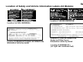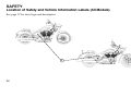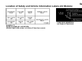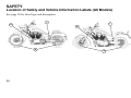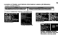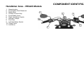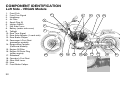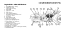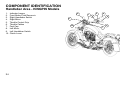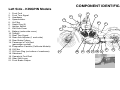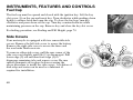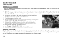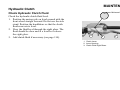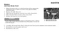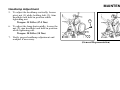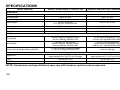
1
California Proposition 65 Warning
This product contains or emits
chemicals known to the state of
California to cause cancer and birth
defects or other reproductive harm.
We’ve created a web site just for YOU!
S Technical tips
S New product introductions
S Event schedules
S Parts and Service Manual information
S Exciting details about The Way Out
Check it out...
www.victory-usa.com
The text, photographs and illustrations used in this manual are based on the most current product information
available at the time of publication. Product improvements or other changes may result in differences between this
manual and the motorcycle. Polaris Industries reserves the right to make production changes at any time, without
notice and without incurring any obligation to make the same or similar changes to motorcycles previously built.
2008 OWNER’S MANUAL
Vegas®
Vegas Lowt
Vegas 8-Ballt
Kingpin®
Kingpin® Tour
Kingpin 8-Ballt
P/N 9921239
VICTORY Motorcycle Division, Polaris Industries Inc.
2100 Highway 55, Medina, Minnesota 55340-9800 Phone: 1-888-704-5290
CopyrightE 2007 Polaris Sales Inc. All rights reserved.
POLARIS, POLARIS THE WAY OUT, FREEDOM, VEGAS, KINGPIN and VICTORY MOTORCYCLES
are registered trademarks of Polaris Industries Inc.
VEGAS 8-BALL, VEGAS LOW and KINGPIN 8-BALL are trademarks of Polaris Industries Inc.
DUNLOP is a registered trademark of Dunlop Tire Corporation. LOCTITE is a registered trademark of LOCTITE Corporation.
Features of VICTORY motorcycles are covered by U.S. Patent Nos.:
6,976,691; 6,407,663; D489670; D482311; D482304; D481980; D481973; D474142
1
FOREWORD
Thank you for choosing a Polaris VICTORY motorcycle!
Some of the photographs and illustrations used in the manual are generalizations, so your model may be slightly
different than what is shown.
If you misplace or damage your owner’s manual, you should purchase a replacement copy from an authorized
VICTORY dealer. This manual should be considered part of the motorcycle, and it should remain with the
motorcycle when it’s sold.
If you have questions about the operation or maintenance of the motorcycle after you’ve read this manual, please
contact an authorized VICTORY dealer. To locate the nearest authorized VICTORY dealer, call 1-800-POLARIS
and provide the area code or zip code of your location. Visit www.polarisindustries.com for a listing of authorized
VICTORY dealers by state, zip code or area code.
Your authorized VICTORY dealer will resolve all issues regarding your motorcycle. If you’re not satisfied with the
performance of your VICTORY dealer, please contact the Polaris Consumer Service Department at 1-888-704-5290.
In Canada, call 204-925-7100.
VICTORY motorcycles comply with all federal, state and local safety and emission regulations for the area of
intended sale.
2
TABLE OF CONTENTS
FOREWORD . . . . . . . . . . . . . . . . . . . . . . . . . . . . . . . . . . . . . . . . . . . . . . . . . . . . . . . . . . . . . . . . . . . . . . . 2
INTRODUCTION . . . . . . . . . . . . . . . . . . . . . . . . . . . . . . . . . . . . . . . . . . . . . . . . . . . . . . . . . . . . . . . . . . . . 4
SAFETY . . . . . . . . . . . . . . . . . . . . . . . . . . . . . . . . . . . . . . . . . . . . . . . . . . . . . . . . . . . . . . . . . . . . . . . . . . . 5
REPORTING SAFETY DEFECTS . . . . . . . . . . . . . . . . . . . . . . . . . . . . . . . . . . . . . . . . . . . . . . . . . . . . 30
COMPONENT IDENTIFICATION . . . . . . . . . . . . . . . . . . . . . . . . . . . . . . . . . . . . . . . . . . . . . . . . . . . . . 31
INSTRUMENTS, FEATURES AND CONTROLS . . . . . . . . . . . . . . . . . . . . . . . . . . . . . . . . . . . . . . . . 39
PRE-OPERATION CHECK . . . . . . . . . . . . . . . . . . . . . . . . . . . . . . . . . . . . . . . . . . . . . . . . . . . . . . . . . . 50
OPERATION . . . . . . . . . . . . . . . . . . . . . . . . . . . . . . . . . . . . . . . . . . . . . . . . . . . . . . . . . . . . . . . . . . . . . . 67
MAINTENANCE . . . . . . . . . . . . . . . . . . . . . . . . . . . . . . . . . . . . . . . . . . . . . . . . . . . . . . . . . . . . . . . . . . . 81
MAINTENANCE RECORD . . . . . . . . . . . . . . . . . . . . . . . . . . . . . . . . . . . . . . . . . . . . . . . . . . . . . . . . . . 86
CLEANING . . . . . . . . . . . . . . . . . . . . . . . . . . . . . . . . . . . . . . . . . . . . . . . . . . . . . . . . . . . . . . . . . . . . . . . 144
STORAGE . . . . . . . . . . . . . . . . . . . . . . . . . . . . . . . . . . . . . . . . . . . . . . . . . . . . . . . . . . . . . . . . . . . . . . . 150
WARRANTIES . . . . . . . . . . . . . . . . . . . . . . . . . . . . . . . . . . . . . . . . . . . . . . . . . . . . . . . . . . . . . . . . . . . . 154
SPECIFICATIONS . . . . . . . . . . . . . . . . . . . . . . . . . . . . . . . . . . . . . . . . . . . . . . . . . . . . . . . . . . . . . . . . . 164
IDENTIFICATION NUMBERS . . . . . . . . . . . . . . . . . . . . . . . . . . . . . . . . . . . . . . . . . . . . . . . . . . . . . . . 169
INDEX . . . . . . . . . . . . . . . . . . . . . . . . . . . . . . . . . . . . . . . . . . . . . . . . . . . . . . . . . . . . . . . . . . . . . . . . . . . 170
3
INTRODUCTION
Read the Owner’s Manual
Your VICTORY owner’s manual contains information that’s essential to safe riding and proper maintenance of the
motorcycle. Anyone who uses the motorcycle (operators and passengers) must read the owner’s manual before
riding.
Carefully read and understand the information found in the safety section beginning on page 5. Understand and
follow the procedures in your owner’s manual to keep your VICTORY motorcycle in top condition on the road or in
storage. Bring the manual with you when you ride. Following the precautions and procedures in the manual will
add to your enjoyment and keep you riding safely.
WARNING
Failure to follow the safety precautions and operation and maintenance procedures outlined in this
manual may result in death or injury (to you or your passenger) or damage to the motorcycle.
4
Symbols and Terms Used in the Owner’s Manual
SAFETY
The following safety signal words and symbols appear throughout the owner’s manual. Your safety and the safety of
others are involved when these words and symbols are used. Become familiar with their meanings before reading
the manual.
!
The safety alert symbol indicates a potential for personal injury to you or others.
WARNING
The safety alert warning indicates a potential hazard that could result in serious injury or death.
Caution
The safety alert caution indicates a potential hazard that may result in minor personal injury or damage to
the motorcycle.
Caution
A caution indicates a situation that may result in damage to the motorcycle.
Notice
A notice highlights important information you must pay attention to.
5
SAFETY
Safe Riding Practices
WARNING
Improper use of this motorcycle can result in serious injury or death to you, your passenger and others.
To minimize the risk of injury, read and understand the information contained in this section before
operating the motorcycle. This section contains safety information specific to the VICTORY motorcycle,
as well as information about general motorcycle safety. Anyone who uses the motorcycle (operators and
passengers) must follow these safety precautions.
Motorcycling has inherent risks. You can minimize those risks, but you can’t eliminate them completely. Even if
you’re an experienced motorcycle operator or passenger, read all of the information in this safety section before
operating the motorcycle.
S Your ability to safely operate the motorcycle depends on your judgment and your use of safe riding habits. Take a
rider education course from the Motorcycle Safety Foundation or another qualified instructor. The course will
help you develop or refresh your expertise in safe riding habits through instruction and riding. For information on
Motorcycle Safety Foundation rider education courses in your area, call 1-800-446-9227 or visit their homepage
at http://msf-usa.org.
S Read and understand all information in this owner’s manual. It contains safety information specific to individual
components and operations.
S Pay close attention to the motorcycle maintenance requirements in this manual. For additional information or
assistance with technical services specified in the manual or required by mechanical circumstances, see the
VICTORY Service Manual or your authorized VICTORY Dealer.
6
Safe Riding Practices
SAFETY
The following design characteristics affect how you should ride the VICTORY motorcycle:
S Some models are designed for one rider and one passenger. Some models are designed for one rider only. Never
carry a passenger on a vehicle designed for a single rider. Never carry more than one passenger on a vehicle designed for only one rider and one passenger.
S The motorcycle is designed for on-road use. Do not exceed the gross vehicle weight rating (see the specifications
section, beginning on page 164, or the certification label on the steering head). Riding off-road or carrying weight
exceeding the maximum weight rating can make handling difficult, which could cause loss of control.
S In the first 500 miles, operate the motorcycle according to the break-in procedures described on page 68. Operating the motorcycle without following break-in procedures can result in serious engine damage.
S Some VICTORY motorcycles include saddlebags, a windshield, and a passenger backrest as standard equipment.
To maintain stability, be prepared to reduce the operating speed of motorcycles equipped with these accessories.
7
SAFETY
Safe Riding Practices
Follow these general safe riding practices:
S Before each ride, make the checks described in the Pre-Operation Check section beginning on page 50.
Operating the motorcycle without completing the pre-operation check may cause damage to the motorcycle or
result in an accident.
S Until you’re thoroughly familiar with the VICTORY motorcycle and all of its controls, practice riding where
there is little or no traffic. Practice riding at a moderate speed on varying road surfaces and under varying weather
conditions.
S Know your skills and limits, and ride within them.
S Allow only licensed, experienced operators to ride your motorcycle, and then only after they have become familiar
with its controls and operation.
S Do not ride when you’re fatigued or under the influence of alcohol, prescription drugs, over-the-counter drugs or
any other drugs. Fatigue, alcohol and drugs can cause drowsiness, loss of coordination and loss of balance. They
can also affect your awareness and judgment.
S If your motorcycle operates abnormally, correct the problem immediately (see the VICTORY Service Manual or
contact your authorized VICTORY dealer). If you continue to operate a motorcycle in this condition, you are
likely to aggravate the initial problem, increase the cost of repairs and threaten your safety.
8
Safe Riding Practices
SAFETY
S The most common cause of accidents involving a motorcycle and an automobile is the automobile driver’s failure
to see the motorcycle. Ride defensively, as if you are invisible to other motorists, even in broad daylight. Ride
where you’re clearly visible to other motorists, and observe their behavior carefully, as they may not see or be
aware of you.
S Be especially cautious at intersections, as these are the most likely places for an accident.
S To prevent loss of control while operating the motorcycle, keep your hands on the handlebars and your feet on the
footrests.
S Obey the speed limit and adjust your speed and riding technique based on road, weather and traffic conditions. As
you travel faster, the influence of all other conditions increases, which can affect the motorcycle’s stability and
increase the possibility of losing control.
S Do not move or operate the motorcycle with the steering locked (with accessory lock), as the severely restricted
steering could result in loss of control.
S Reduce your speed when:
- The road has potholes or is otherwise rough or uneven.
- The road has sand, dirt, gravel or other loose substances on it.
- The road is wet, icy or oily.
- The road contains painted surfaces, manhole covers, metal grating, railway crossings or other slippery
surfaces.
9
SAFETY
Safe Riding Practices
S Reduce your speed when:
- The weather is windy, rainy or otherwise causing slippery or rapidly changing conditions.
- The traffic is heavy, congested, not allowing sufficient space between vehicles or otherwise not flowing
smoothly.
- You are being passed in either direction by a large vehicle that produces a wind blast in its wake.
S To maximize braking effectiveness, use the front and rear brakes together. Improper braking may cause loss of
control or may not slow the vehicle in time to avoid a collision. Be aware of the following braking facts and practices:
- The rear brake provides 40% of the motorcycle’s stopping power, at most.
- Consider road conditions before applying the brakes. When the road is wet or rough, or contains loose or
other slippery substances, apply the brakes gradually.
- Bring the motorcycle to the upright position before applying the brakes, and avoid applying the brakes in a
corner if at all possible. When the motorcycle is leaning through a corner, the amount of traction available
for braking is reduced, increasing the possibility of the tires skidding when the brakes are applied.
S When approaching a curve, choose a speed and lean angle that allows you to pass through the curve in your own
lane without applying the brakes. Excessive speed, improper lean angle or braking in a curve can cause loss of
control.
10
Safe Riding Practices
SAFETY
S Ground clearance is reduced when the motorcycle leans. Do not allow components to contact the road surface
when leaning the motorcycle in a curve, as this could cause loss of control.
S Retract the sidestand fully before riding. If the sidestand is not fully retracted, it could contact the road surface
and cause loss of control.
S Do not tow a trailer. Towing a trailer can make the motorcycle hard to handle, which could cause loss of control.
Carrying a Passenger
NOTE: Some models are designed for a single rider only. Single-rider models are not equipped with a passenger seat
or passenger footrests. DO NOT carry a passenger on motorcycles not properly equipped for a passenger.
To carry a passenger safely, do the following:
S Direct the passenger to hold onto you or the seat strap with both hands and to keep both feet on the passenger
footrests. Do not carry a passenger who cannot place both feet firmly on the passenger footrests. A passenger who
is not holding on properly, or who cannot reach the passenger footrests, can shift their body erratically, which can
make the motorcycle hard to handle and cause loss of control.
S If necessary, adjust the rear shock absorber preload according to the instructions on page 100. Improper preload
adjustment can make your motorcycle hard to handle and can cause loss of control.
S Before riding, be sure your passenger knows safe riding procedures. Discuss any safety information unfamiliar to
your passenger. A passenger who is unaware of safe riding procedures may distract you or make movements that
make the motorcycle hard to handle.
S Adjust your riding style to compensate for the differences in handling, acceleration and braking caused by the
additional weight of the passenger. Failure to do so can cause loss of control.
11
SAFETY
Safe Riding Practices
Protective Apparel
To decrease the risk of injury and increase riding comfort, wear protective riding apparel.
S Wearing a helmet can prevent a severe head injury. Always wear a helmet that meets or exceeds established safety
standards. Approved helmets in the USA and Canada bear a U.S. Department of Transportation (DOT) label. In
accidents involving motorcycles, head injuries are the leading cause of motorcyclist fatalities, and statistics
prove that an approved helmet is the most effective protection in preventing or reducing head injuries.
S Wear eye protection. Some state laws require that you wear eye protection. Eye protection reduces the chance that
your vision could be impaired by wind or by airborne particles and objects.
S You and your passenger should wear bright or light colored and/or reflective clothing to improve visibility to other motorists. A motorist’s failure to see or recognize a motorcycle is the leading cause of automobile/motorcycle
accidents.
S Wear gloves, a jacket, heavy boots and long pants to prevent or reduce abrasions, lacerations or burns should the
motorcycle fall.
S Wear boots with low heels, as high heels can catch on pedals or footrests. The combination of boots and pants
should completely cover legs, ankles and feet, protecting skin from engine and exhaust system heat. The engine
and exhaust system get hot soon after the engine is started and stay hot for about half an hour after the engine is
turned off.
S Do not wear loose, flowing clothing or long boot laces, as they can catch on handlebars, levers or footrests, or
become entangled in the wheels, causing loss of control and serious injury.
12
Gross Vehicle Weight Rating (GVWR)
SAFETY
Gross vehicle weight is the total combined weight of the motorcycle, the operator and the passenger. Examples of
calculating GVWR are provided on the following pages.
Do not exceed the motorcycle’s gross vehicle weight rating. Exceeding the weight rating can reduce stability and
handling and could cause loss of control. Refer to the specifications section of this manual beginning on page 164 or
the certification label on your motorcycle’s steering head for model-specific GVWR information.
S The weight of the motorcycle includes the motorcycle and all of its fluids, any accessories and their contents, and
any additional cargo on the motorcycle.
S The weight of the operator or passenger includes body weight, all apparel and objects in or on apparel.
13
SAFETY
Loading Examples
EXAMPLE 1:
VEGAS
with no accessories or cargo.
Gross Vehicle Weight Rating:
1151 lbs (522 kg)
EXAMPLE 2:
VEGAS
with accessory saddlebags.
Gross Vehicle Weight Rating:
1151 lbs (522 kg)
Item
Weight
Motorcycle with full capacity of all fluids
686 lbs (311 kg)
Operator with recommended riding apparel
230 lbs (104 kg)
Passenger with recommended riding apparel (passenger models)
165 lbs (75 kg)
Total Weight
Item
Weight
Motorcycle with full capacity of all fluids
Weight of leather saddlebags and brackets
Cargo (saddlebags at capacity)
Operator with recommended riding apparel
Passenger with recommended riding apparel (passenger models)
Total Weight
EXAMPLE 3:
VEGAS LOW
with no accessories or cargo.
cargo
Gross Vehicle Weight Rating:
1134 lbs (514 kg)
1081 lbs (490 kg)
Item
686 lbs (311 kg)
12 lbs (5.5 kg)
14 lbs (6 kg)
230 lbs (104 kg)
165 lbs (75 kg)
1107 lbs (502 kg)
Weight
Motorcycle with full capacity of all fluids
679 lbs (308 kg)
Operator with recommended riding apparel
230 lbs (104 kg)
Total Weight
909 lbs (412 kg)
NOTE: As shown in Example 2, the weight of any accessory items (leather saddlebags and the brackets) in addition
to the cargo, must be added to the base weight of the motorcycle. NEVER exceed GVWR. If you have any questions regarding safe loading of your VICTORY motorcycle, please consult an authorized VICTORY dealer.
14
SAFETY
Loading Examples
EXAMPLE 4:
KINGPIN
with no accessories or cargo.
Gross Vehicle Weight Rating:
1234 lbs (560 kg)
EXAMPLE 5:
KINGPIN TOUR
with cargo.
Gross Vehicle Weight Rating:
1234 lbs (560
(
kg)
g)
Item
Weight
Motorcycle with full capacity of all fluids
704 lbs (319 kg)
Operator with recommended riding apparel
230 lbs (104 kg)
Passenger with recommended riding apparel (passenger models)
165 lbs (75 kg)
Total Weight
Item
1099 lbs (498 kg)
Weight
Motorcycle with full capacity of all fluids
Cargo (top box at capacity)
Cargo (saddlebags at capacity)
Operator with recommended riding apparel
Passenger with recommended riding apparel (passenger models)
Total Weight
769 lbs (349 kg)
20 lbs (9 kg)
14 lbs (6 kg)
230 lbs (104 kg)
165 lbs (75 kg)
1198 lbs (543 kg)
NOTE: The weight of any accessory items such as saddlebags and brackets, or individual items in addition to the
cargo, must be added to the base weight of the motorcycle. NEVER exceed GVWR. If you have any questions regarding safe loading of your VICTORY motorcycle, please consult an authorized VICTORY dealer.
15
SAFETY
Carrying Cargo
Use the following guidelines when attaching cargo or accessories to the motorcycle. Where applicable, these
guidelines also refer to the contents of any accessories.
S Keep cargo and accessory weight to a minimum, and keep items as close to the motorcycle as possible to minimize a change in the motorcycle’s center of gravity. Changing the center of gravity can cause loss of stability and
handling and result in loss of control.
S Distribute weight evenly on both sides of the motorcycle. Maintain even weight distribution by checking accessories and cargo to make sure they’re securely attached to the motorcycle before riding and whenever you take a
break from riding. Uneven weight distribution, or accessories or cargo that shift suddenly while you’re riding can
make the motorcycle hard to handle and result in loss of control.
S Do not attach large or heavy cargo such as sleeping bags, duffel bags or tents to the handlebars, front fork area or
front fender. Cargo or accessories placed in these areas can cause instability (due to improper weight distribution
or aerodynamic changes) and can cause loss of control. Such items can also block air flow to the engine and
cause overheating that can damage the engine.
S Do not exceed the maximum cargo weight limit of any accessory (see accessory instructions and labels), and do
not attach cargo to an accessory not designed for that purpose, as these could result in an accessory failure that
could cause loss of control.
S Except for highway footrests, do not attach anything else to the highway bar.
16
Saddlebags / Top Box
SAFETY
When operating a motorcycle with original equipment or accessory saddlebags:
S Never ride at speeds exceeding 80 mph (129 km/h). Depending on load and weather conditions, the maximum
safe operating speed may be less than 80 mph (129 km/h). Saddlebags, combined with the lifting or buffeting
effects of wind, can make the motorcycle unstable and cause loss of control.
S Distribute weight evenly in each of the saddlebags.
S Do not exceed the maximum cargo weight limit of the saddlebags.
Accessory leather saddlebags, semi-hard saddlebags, or hard saddlebags = 7 lbs. (3.2 kg) each
Top Box weight capacity (Kingpin Tour) = 20 lbs. (9.0 kg)
S Do not exceed the motorcycle’s gross vehicle weight rating. Exceeding the weight rating can reduce stability and
handling and cause loss of control.
17
SAFETY
Modifications
Modifying the motorcycle by removing any equipment or by adding equipment not approved by VICTORY may
void your warranty. Such modifications may make the motorcycle unsafe to ride and could result in severe injury to
operator or passengers, as well as damage to the motorcycle. Some modifications may also be illegal in some states.
If in doubt, contact your authorized VICTORY Dealer.
Parking the Motorcycle
When leaving the motorcycle unattended, turn the engine off and remove the ignition key. See page 79.
Park the motorcycle where people are not likely to touch the hot engine or exhaust system or place combustible
materials in close proximity to these hot areas. Do not park near a flammable source such as a kerosene heater or an
open flame, where hot components could ignite combustible materials.
Park the motorcycle on a firm, level surface. Sloped or soft surfaces may not support the motorcycle when it’s
parked, and it may tip over. If you must park on a slope or soft surface, follow the precautions outlined on page 79.
18
SAFETY
Transporting the Motorcycle
If you must transport the motorcycle:
S Use a truck or trailer. Do not tow the motorcycle with another
vehicle, as towing will impair the motorcycle’s steering and
handling, which can cause loss of control.
S Position and restrain the motorcycle so it remains upright on
the truck or trailer, as gasoline may leak out of the fuel tank if
the motorcycle leans to one side. Gasoline is a fire hazard and
it can also damage the motorcycle’s finish.
S Place the transmission in neutral.
S Do not restrain the motorcycle using the handlebars. Loosen
the front turn signal mounts and slide them up to make room
for the tiedown strap. Place tie-downs around the fork tubes
above the lower triple clamp. Secure the rear of the motorcycle
with tiedowns around the swingarm, being careful to avoid the
brake line, exhaust, and drive belt. Reposition the turn signals
after transportation.
Loosen screw,
slide turn signal up
KINGPIN
VEGAS
19
SAFETY
Accessory Selection and Installation
Because VICTORY cannot test and make specific recommendations concerning every accessory or combination of
accessories sold, the operator is responsible for determining that the motorcycle can be safely operated with any
accessories or additional weight. Use the following guidelines when choosing and installing accessories:
S Do not install accessories that impair the stability, handling or operation of the motorcycle. Before installing an
accessory, be sure that it does not:
- Reduce ground clearance when the motorcycle is either leaned or in a vertical position.
- Limit suspension or steering travel or your ability to operate controls.
- Displace you from your normal riding position.
- Obscure lights or reflectors.
S Bulky or large accessories can cause instability (due to the lifting or buffeting effects of wind) and loss of control.
S Do not install electrical accessories that exceed the capacity of the motorcycle’s electrical system. Never install
higher wattage light bulbs than those supplied as original equipment. An electrical failure could result and cause
hazardous loss of engine power or lights or damage to the electrical system.
S If you want to add a windshield, backrest or luggage rack, choose one designed and approved by VICTORY specifically for your model. Follow the instructions for proper installation and use. An improperly designed or
installed windshield, backrest or luggage rack can reduce stability, causing loss of control.
20
Gasoline and Exhaust
SAFETY
For complete fueling procedures, see page 70.
Gasoline is highly flammable and can be explosive in certain conditions. Observe the following precautions when
you refuel or service the fuel system:
S Turn off the engine.
S Use a well-ventilated area.
S Open the fuel cap slowly.
S Do not spill gasoline on the engine or the exhaust system. Immediately wipe, or rinse with water, gasoline spilled
on any part of the motorcycle or the surrounding area.
S Do not smoke while fueling.
S Do not fuel in an area where there are sparks or open flame.
Gasoline and gasoline vapors are poisonous and can cause severe injury. Do not swallow gasoline, inhale gasoline
vapors, or spill gasoline on yourself or your clothes. If you swallow gasoline, inhale more than a few breaths of
gasoline vapor, or get gasoline in your eyes, see a physician immediately. If you spill gasoline on your skin, wash it
off immediately with soap and water. If you spill gasoline on your clothes, change your clothes immediately.
Exhaust gases contain carbon monoxide, a colorless, odorless gas that can cause unconsciousness or severe injury.
Observe the following precautions to avoid the effects of exhaust gases:
S Do not inhale exhaust gases.
S Do not start or run the engine in an enclosed area.
21
SAFETY
Maintenance
Maintain the motorcycle according to the following requirements:
S Before each ride, complete a pre-operation check as outlined beginning on page 50. Operating the motorcycle
without completing the pre-operation check can cause damage to the motorcycle or result in an accident.
S Perform periodic maintenance according to the intervals outlined in the Periodic Maintenance Interval tables beginning on page 82. Operating the motorcycle without performing periodic maintenance can damage the motorcycle or result in bodily injury.
S Maintain proper tire pressure and tread condition and proper wheel and tire balance. Inspect tires regularly and
replace them if they’re worn or damaged. Use only an approved replacement tire and see the VICTORY Service
Manual or your authorized VICTORY Dealer for tire replacement. Operating the motorcycle with improper tire
pressure or tread condition, or improper wheel or tire balance, can make the motorcycle hard to handle and cause
loss of control.
S Check proper steering head bearing adjustment. Regularly inspect the rear shock absorber and the front forks.
Check for fork oil or shock absorber fluid leaks. Operating the motorcycle with a loose, worn, or damaged steering system or front or rear suspension system can make the motorcycle hard to handle and cause loss of control.
To repair steering or suspension system wear or damage, see the VICTORY Service Manual or contact your authorized VICTORY Dealer.
22
Maintenance
SAFETY
S Keep the motorcycle clean. In addition to extending the service life and the original appearance of the motorcycle, a complete and thorough cleaning can reveal items in need of repair. For complete cleaning procedures, see
page 144.
S Keep equipment required by federal, state, and local laws in place and in good working condition. Your license
plate must be clean, clearly visible in all conditions, and installed in a position specified by law.
S Each fastener used in the motorcycle meets our quality specifications for strength, finish and type. When replacement fasteners are needed, use only genuine VICTORY parts, tightened to the proper torque. A fastener that does
not meet original specifications could fail and result in damage to the motorcycle or injury to riders.
Electromagnetic Interference
This vehicle complies with European directive 97/24/EC Chapter 8 requirements, which is equivalent to Canadian
ICES-002.
23
SAFETY
Location of Safety and Vehicle Information Labels (All Models)
See page 25 for decal type and description.
A
D
B
D
A
E
C
B
E
24
C
Location of Safety and Vehicle Information Labels (All Models)
SAFETY
Location C (NOISE EMISSION)
Location A (FUEL WARNING)
Location B (MANUFACTURING INFORMATION)
Information varies by model
Location D (TIRE INFORMATION)
(Under Left Side Cover)
Information varies by model
Location E (ENGINE I.D.)
(on right rear crankcase half)
25
SAFETY
Location of Safety and Vehicle Information Labels (All Models)
See page 27 for decal type and description.
F
26
Location of Safety and Vehicle Information Labels (All Models)
Location F
FUSE and RELAY LOCATION
(Under right side cover, on side of fuse box cover)
SAFETY
FUSE BOX REMOVAL
(on base of fuse box)
27
SAFETY
Location of Safety and Vehicle Information Labels (All Models)
See page 29 for decal type and description.
I
H
G
28
I
H
G
Location of Safety and Vehicle Information Labels (All Models)
SAFETY
Location G (TIRE SAFETY)
Location H (EMISSION CONTROL INFORMATION)
Canada Models
49 State Models
Catalyst Models Only
Location I (PATENT NOTICE)
(LH Rear of subframe down tube)
Information varies by model
29
SAFETY
Reporting Safety Defects
If you believe that your vehicle has a defect that could result in a crash or cause injury or death, you should
immediately inform the National Highway Traffic Safety Administration (NHTSA) in addition to notifying Polaris
Industries in writing.
If NHTSA receives similar complaints, it may open an investigation, and if it finds that a safety defect exists in a
group of vehicles, it may order a recall and remedy campaign. However, NHTSA cannot become involved in
individual problems between you, your dealer or Polaris Industries.
To contact NHTSA, or obtain other information about motor vehicle safety, you may either call the Vehicle Safety
Hotline toll-free at 1-888-327-4236 (TTY 1-800-424-9153), visit the NHTSA website at www.safercar.gov, or write
to:
ADMINISTRATOR
NHTSA
US Department of Transportation
400 7th Street Southwest
Washington, DC 20590
30
COMPONENT IDENTIFICATION
Handlebar Area - VEGAS Models
1.
2.
3.
4.
5.
6.
7.
8.
9.
10.
11.
Speedometer
Front Brake Fluid Reservoir
Right Mirror
Throttle Control Grip
Front Brake Lever
Right Handlebar Switch
Indicator Lamps
Fuel Cap
Left Handlebar Switch
Clutch Lever
Left Mirror
3
11
1
2
10
4
9
8
7
5
6
31
COMPONENT IDENTIFICATION
Left Side - VEGAS Models
1.
2.
3.
4.
5.
6.
7.
8.
9.
10.
11.
12.
13.
14.
15.
16.
17.
18.
19.
20.
21.
32
Front Fork
Front Turn Signal
Headlamp
Air Filter
Spark Plug (2)
Ignition Switch
Left Side Cover
Battery (under side cover)
Taillight
Rear Turn Signal
Rear Axle Adjuster (1 each side)
Rear Brake Caliper
Passenger’s Foot Rest
(passenger models)
Evaporative Canister
(California Models)
Engine Oil Filter
Engine Oil Drain Plug
(under engine)
Sidestand
Operator’s Foot Rest
Gear Shift Lever
Horn
Front Brake Caliper
4
6
5
7
8
3
9
2
1
17
10
21
20
19
18
17
16
15
14
13
12
11
COMPONENT IDENTIFICATION
Right Side - VEGAS Models
1. Drive Belt (under guard)
2. Passenger Seat
(passenger models)
3. Seat Strap
4. Operator’s Seat
5. Side Cover
6. Rear Shock Absorber
(access through RH side cover)
7. Front Turn Signal
8. Front Fork
9. Rear Brake Pedal
10. Operator Foot Rest
11. Engine Oil Fill Cap/Dipstick
12. Rear Brake Fluid Reservoir
(under side cover)
13. Drive Sprocket (under cover)
14. Fuses (under side cover)
15. Diagnostic Connector
16. Passenger Foot Rest (passenger models)
17. Exhaust Mufflers
2
1
3
7
6
5
4
8
17
14
16
13
12
11
10
9
15
33
COMPONENT IDENTIFICATION
Handlebar Area - KINGPIN Models
1.
2.
3.
4.
5.
6.
7.
8.
9.
10.
34
Indicator Lamps
Front Brake Fluid Reservoir
Right Handlebar Switch
Right Mirror
Throttle Control Grip
Throttle Cables
Fuel Cap
Left Mirror
Left Handlebar Switch
Clutch Lever
8
1
3
4
2
5
9
10
6
7
COMPONENT IDENTIFICATION
Left Side - KINGPIN Models
1.
2.
3.
4.
5.
6.
7.
8.
9.
10.
11.
12.
13.
14.
15.
16.
17.
18.
19.
20.
21.
Front Fork
Front Turn Signal
Headlamp
Speedometer
Air Filter
Spark Plug (2)
Ignition Switch
Left Side Cover
Battery (under side cover)
Taillight
Rear Turn Signal
Rear Axle Adjuster (1 each side)
Rear Brake Caliper
Passenger’s Foot Rest
(passenger models)
Evaporative Canister (California Models)
Oil Filter
Oil Drain Plug (on bottom of crankcase)
Sidestand
Operator’s Foot Rest
Gear Shift Lever
Front Brake Caliper
6
5
4
7
3
8
9
10
2
1
11
21
20
19
18
17
16
15
14
13
12
35
COMPONENT IDENTIFICATION
Right Side - KINGPIN Models
1.
2.
3.
4.
5.
6.
7.
8.
9.
10.
11.
12.
13.
14.
15.
16.
17.
18.
19.
36
Passenger’s Seat (passenger models)
Seat Strap
Operator’s Seat
Rear Shock Absorber
(access through RH side cover)
Side Cover
Engine Oil Fill Cap/Dipstick
Front Brake Lever
Front Turn Signal
Horn
Front Fork
Rear Brake Pedal
Operator’s Foot Rest
Rear Brake Fluid Reservoir
Drive Sprocket (under cover)
Fuses (under side cover)
Diagnostic Connector
Passenger Foot Rest (passenger models)
Drive Belt (under guard)
Exhaust Mufflers
1
2
4
3
5
6
7
8
9
10
19
18
17
16
15
14
13
12
11
COMPONENT IDENTIFICATION
Vehicle Identification Number
The vehicle identification number (VIN) is stamped into the front of the steering head and also appears on the
certification label. You will need the vehicle identification number to title, register, license or insure the motorcycle,
or to order replacement parts.
Chassis:
A = VEGAS 8-BALL
B = NESS JACKPOT
C = KINGPIN
D = NESS SIGNATURE SERIES KINGPIN
E = NESS SIGNATURE SERIES VEGAS
G = VEGAS
H = HAMMER
L = VEGAS LOW
P = KINGPIN 8-BALL
T = TOURING
X = VEGAS JACKPOT
Type:
B = Standard
C = Custom
D = Deluxe
S = Sport
Series:
C = Canada
D = Domestic (49 State)
L = California
U = United Kingdom
Serial Number
*5VPGB26D073000000*
Plant Code
SAE - assigned
World Manufacturing Identifier
Engine Size:
1 = 1507 cc
2 = 1634 cc
Engine HP:
6 = 78-94
Check Digit
Model Year:
8 = 2008
37
COMPONENT IDENTIFICATION
Engine Identification Number
The engine identification number is a combination of the engine model
and serial numbers. The first 8 digits are the engine model number and
the last 5 digits are the serial number.
The engine serial number is stamped into the rear upper portion of the
right crankcase behind the rear cylinder. You may need the engine
identification number to title, register, license or insure the motorcycle,
or to order replacement parts.
Ignition Key Number
The ignition key identification number is stamped into the shaft of
each key.
With the ignition key number and proof of ownership, an authorized
VICTORY dealer can assist you in obtaining a replacement key.
Notice
38
For easy reference, record all vehicle numbers in the space provided on page 169.
Ignition Key
INSTRUMENTS, FEATURES AND CONTROLS
The ignition key operates the ignition switch and parking lights.
Ignition Switch
The ignition switch energizes the ignition, the lighting system, and all
electrical switches and buttons.
Off Position
In the OFF position, all electrical circuits are inactive and the ignition
key can be removed. Turn the ignition switch to the OFF position and
remove the ignition key when leaving the motorcycle unattended.
On Position
In the ON position, all electrical circuits are energized and the ignition
key cannot be removed. The headlamp, taillight, and instrument lights
illuminate. With the engine stop/run switch set to the RUN position (see
page 46) you can start the engine. You can also activate the emergency
flashers, turn signals and all other electrical features.
Caution
3
2
1
1. Off
2. On
3. P (Park)
Before starting the engine, read the instructions for starting the engine beginning on page 71.
Park Position (P)
In the PARK position, the taillight, indicator lights, and license plate light illuminate, the emergency flashers can be
activated, and the ignition key can be removed. You must push the ignition key into the switch while selecting the
Park position.
39
INSTRUMENTS, FEATURES AND CONTROLS
Instrument Cluster
The instrument cluster includes the speedometer, the tachometer
(accessory) and the multi-function display.
1. Speedometer
2. Odometer / Trip Odometer
3. Odometer & Trip Odometer Toggle / Trip Odometer Reset
1
2
Speedometer
The speedometer reports current motorcycle speed in miles per hour
(mph) or kilometers per hour (kph), Canada.
3
Odometer
The odometer display shows total miles traveled in the window on the lower
portion of the speedometer.
Trip Odometer
A trip odometer is included on the speedometer. The trip odometer shows total miles traveled since the trip
odometer was reset. You can use the trip odometer to calculate your miles per gallon and estimate the number of
miles you can travel on a tank of fuel.
To toggle the display between Odometer and TRIP Odometer, the ignition switch must be in the ON position. Press
the reset button (3). The display changes to “TRIP”.
To reset the trip odometer, the ignition switch must be in the ON position with the display in trip odometer mode.
Press and hold the reset button (3) until the TRIP odometer display resets to zero.
40
Tachometer (Accessory)
INSTRUMENTS, FEATURES AND CONTROLS
Some models are equipped with a tachometer (1). An accessory
tachometer kit can also be purchased as an accessory through your
VICTORY dealer. The tachometer reports current engine speed in
revolutions per minute (RPM). A red line on the gauge indicates
maximum safe engine RPM. With tachometer installed, the trip
odometer reset button (2) is located on the instrument mounting
plate. See page 40.
1
2
WARNING
Do not operate the engine over 5600 RPM. Excessive RPM could cause engine damage or failure that could
result in you losing control of the motorcycle.
Overdrive Indicator Lamp
The overdrive lamp (3) illuminates when O/D (6th gear) is selected
(tachometer-equipped 100/6 engine only).
3
41
INSTRUMENTS, FEATURES AND CONTROLS
Indicator Lights
Neutral Indicator (1)
The neutral indicator illuminates when the transmission is
in neutral, and the ignition key is ON.
1
2
3
Headlamp High Beam Indicator (2)
The headlamp high beam indicator illuminates when the
headlamp switch is set to high beam (see page 44).
Check Engine Indicator (3)
The check engine indicator will illuminate any time the ignition switch is in the ON position and the engine
control module sensors report abnormal sensor or engine operation. The check engine indicator will
continue to illuminate as long as the fault condition exists. It also illuminates momentarily when the
ignition switch is in the ON position and the engine is not running. This demonstrates that the indicator is
functioning properly.
Caution
If the check engine indicator illuminates while the engine is running, a serious engine problem may exist.
Contact an authorized VICTORY dealer as soon as possible.
42
Indicator Lights
INSTRUMENTS, FEATURES AND CONTROLS
Low Oil Pressure Indicator (4)
The low oil pressure indicator illuminates when engine oil pressure drops below safe operating pressure. If
this indicator illuminates while the engine is running, turn the engine off immediately and check the oil
level. Add oil if necessary. If the oil level is correct and the indicator remains illuminated after the engine is
restarted, turn the engine off immediately.
The low oil pressure indicator also illuminates when the ignition switch is in the ON position and the engine
is not running. This demonstrates that the indicator is functioning properly.
Turn Signal Indicator (5)
The turn signal indicator flashes when the left, right, or
both turn signals (hazard) are active.
If a turn signal bulb has failed, or if there is a short circuit in
the turn signal system, the turn signal indicator flashes at more
than twice the normal rate.
Low Fuel Indicator (6)
The low fuel indicator illuminates when approximately
0.8 gallons (3.0 liters) of fuel remains in the fuel tank.
4
5
6
43
INSTRUMENTS, FEATURES AND CONTROLS
Left Handlebar Controls
Emergency Flasher Switch
The emergency flasher switch activates and
cancels the emergency flashers. When the
emergency flashers are active, all of the turn
signals flash. Press the top of the switch to
activate the emergency flashers. Press the bottom
of the switch to cancel the flashers.
2
4
Headlamp High/Low Beam Switch
The headlamp high/low beam switch toggles the
headlamp between high beam, low beam, and
momentary passing beam. To activate the high
beam, press the upper portion of the switch; to
activate the low beam, press the lower portion of the
switch. To activate the momentary passing beam, press
and hold the lower portion of the switch.
Horn Button
To sound the horn, press the horn button.
44
1
5
3
1.
2.
3.
4.
5.
Emergency Flasher Switch
Headlamp High/Low Beam Switch
Horn Button
Turn Signal Switch
Clutch Lever
Left Handlebar Controls
INSTRUMENTS, FEATURES AND CONTROLS
Turn Signal Switch Operation
With the ignition key in the ON or PARK position, the turn signal switch activates the turn signals. Push
the switch to the left to activate the left turn signals, and to the right to activate the right turn signals. To
manually cancel either turn signal, push the switch in toward the housing when in the centered position.
If activated below 15 mph*, the turn signals cancel automatically shortly after the vehicle speed reaches 15 mph
(24.1 kph). If a signal is activated with vehicle speed above 15 mph, cancelation will occur based on distance
traveled. NOTE: If a signal is activated at speeds above 15 mph and vehicle speed drops below 15 mph,
cancellation will occur shortly after speed again reaches 15 mph. (*The 15mph speed is approximate)
Turn Signal Switch - Momentary Feature
When passing a vehicle or when changing lanes, the operator has the option of using the momentary feature
built in to the turn signal auto-cancel system. Push and hold the turn signal switch in the direction you wish
to turn. Hold the switch through at least one complete flash cycle (at least 1 second). This activates the
momentary feature, and the signal will cancel upon release of the switch.
Clutch Lever
To disengage the clutch, pull the lever toward the handlebar. To engage the clutch, gradually release the lever. For
smooth clutch operation, pull the lever quickly and release it gradually.
Notice
The motorcycle is equipped with a clutch interlock switch that prevents the engine from starting when the
transmission is in gear and the clutch is engaged (see page 71).
45
INSTRUMENTS, FEATURES AND CONTROLS
Right Handlebar Controls
Engine Stop/Run Switch
The engine stop/run switch completes or interrupts the ignition, starter, and
fuel pump circuits. To complete the circuits, allowing the engine to start and
run, press the lower portion of the engine stop/run switch (RUN position).
To interrupt the circuits, press the upper portion of the switch (STOP
position). The engine should not start or run when the switch is in the STOP
position.
1
2
Use the engine stop/run switch to turn the engine off under either normal or
emergency conditions.
Starter Button
The starter button works only when the engine stop/run switch is in the RUN
position and the transmission is in neutral or the clutch is disengaged. To
engage the engine starter motor, press the right side of the starter button. For
complete engine starting procedures, see Starting the Engine, page 71.
3
Throttle Control Grip
The throttle control grip controls the engine speed. To increase engine speed, twist
the throttle control grip toward you. To decrease engine speed, twist the grip away
from you. When you release the grip, it returns to the idle speed position.
Front Brake Lever
4
1.
2.
3.
4.
Engine Stop/Run Switch
Starter Button
Throttle Control Grip
Brake Lever
The front brake lever is located on the far side of the right handlebar grip. To apply the front brake, pull the front
brake lever toward the handlebar. For braking procedures in various riding conditions, see Braking (page 77).
46
Gear Shift Pedal
INSTRUMENTS, FEATURES AND CONTROLS
The gear shift pedal (1) is located on the left side
of the motorcycle. To shift to a lower gear, press
down on the gear shift pedal. To shift to a higher
gear, lift up on the gear shift pedal.
For proper gear shifting procedure, see Shifting
Gears, pages 73 and 74.
1
1
Rear Brake Pedal
The rear brake pedal (2) is on the right side of the
motorcycle. To engage the rear brake, press down
on the rear brake pedal.
For braking procedures in various riding
conditions, see Braking, page 77.
2
2
47
INSTRUMENTS, FEATURES AND CONTROLS
Fuel Cap
The fuel cap must be opened and closed with the ignition key. Lift the key
slot cover (1) on the cap and insert key. Turn clockwise while pushing down
lightly to release latch and open the cap. To close the fuel cap, turn key
clockwise and press down on the cap. Turn key counterclockwise while
maintaining pressure on the cap. Remove key and close the key slot cover.
1
For fueling procedure, see Fueling and Fill Height, page 70.
Side Covers
Your motorcycle is equipped with two removable side
covers. Remove the left side cover to access the battery.
Remove the right side cover to access the fuses and
the rear brake fluid reservoir.
To remove either side cover, pull the rear corner of the
side cover out slightly until tab (1) is disengaged. Pull
lower edge (2) out and then front edge (3) to
disengage remaining tabs and remove cover. Be sure
rubber grommets are in place before reversing the
above procedure to install the side covers. A solution of
dish soap and water can be used as a lubricant if
required for installation.
48
3
2
1
INSTRUMENTS, FEATURES AND CONTROLS
Sidestand
The sidestand (1) is located on the left side of the motorcycle.
To extend the sidestand, swing it out from the end until it is fully
extended. Lean the motorcycle toward the sidestand until the
sidestand firmly supports the motorcycle.
To retract the sidestand, lean the motorcycle away from the
sidestand until the motorcycle is fully upright. Swing the sidestand
back into its fully retracted position.
1
WARNING
Correctly retract the sidestand before operating the motorcycle. An improperly retracted sidestand could
come into contact with the ground and cause loss of control.
49
PRE-OPERATION CHECK
To keep your VICTORY motorcycle in good operating condition, always perform the checks described in this
section before each ride. This is especially important before making a long trip or when removing the motorcycle
from storage. You must be familiar with the VICTORY motorcycle instruments and controls to make these checks.
You can find additional service information in the maintenance section of this manual, in the VICTORY Service
Manual or from an authorized VICTORY dealer.
During the pre-operation check you might use products that are potentially hazardous, such as oil or brake fluid.
When using any of these products, follow the instructions and warnings on the product packaging.
WARNING
Failure to perform these checks before operating the motorcycle may result in serious injury or damage.
Adjust components designed for normal wear adjustment, and repair or replace worn or damaged
components as needed.
50
Check Electrical Equipment
PRE-OPERATION CHECK
To perform a pre-operation check on the electrical equipment, set the ignition switch to the ON position. Set the
ignition switch to the OFF position after completing the electrical equipment portion of the pre-operation check.
Indicator Lights
The low oil pressure indicator should illuminate until the engine is started. If the transmission is in neutral, the
neutral indicator should remain illuminated.
Headlamp
Check the headlamp to see that it is on. Set the headlamp switch to the high beam position. The headlamp
brightness should increase and the headlamp high beam indicator light should illuminate.
Taillight / Brake Light
With the ignition switch in the ON position, the taillight and the license plate light should illuminate. Apply slight
pressure to the front brake lever; taillight brightness should increase. Apply slight pressure to the rear brake pedal;
taillight brightness should increase.
51
PRE-OPERATION CHECK
Check Electrical Equipment
Turn Signals
Move the turn signal switch to the left. The front and rear left turn signals and the turn signal indicator light on the
panel should flash. Push the switch button IN to cancel the turn signal. The turn signals and turn signal indicator
should stop flashing. Repeat the procedure for the right turn signals.
Emergency Flashers
Press the top of the switch to activate the emergency flashers. All four turn signals and the turn signal indicator light
on the panel should flash. Press the bottom of the switch to cancel the flashers. The turn signals and turn signal
indicator should stop flashing.
Horn
Press the horn button. The horn should sound loudly.
Engine Stop/Run Switch
Be sure the engine stop/run switch stops the engine, or prevents the engine from starting when set to the STOP
position.
Notice
52
If you regularly use this switch to shut off the engine, you’re already checking its operation each time you
use the motorcycle.
Check Engine Oil Level
A dipstick attached to the oil fill cap registers the engine oil level.
We recommend the use of only VICTORY brand Semi-Synthetic
20W-40 Motor Oil or an equivalent oil designed for use with wet
clutches (such as those with a JASO MA rating).
1. With the transmission in neutral, start and run the engine for
several minutes.
2. Shut the engine off and wait for 3-5 minutes.
3. Straddle the motorcycle on level ground and bring it to a
vertical position. Remove the oil fill cap/dipstick (1) and wipe
the dipstick clean. Reinstall the dipstick and turn the cap
clockwise until it seats.
4. Remove the dipstick again and read the oil level.
5. If necessary, add or remove oil to bring the level into the area
on the dipstick above the ADD mark and below the FULL
mark. Repeat step 1 and step 2 each time you adjust the oil
level.
PRE-OPERATION CHECK
1
2
3
1. Oil Fill Cap/Dipstick
2. ADD Mark
3. FULL Mark
WARNING
Do not operate the motorcycle with the oil level above the FULL mark or below the ADD mark.
Operating the engine with too much or too little oil can cause serious engine damage or engine seizure,
resulting in loss of control.
53
PRE-OPERATION CHECK
Check Fuel Components
Fuel Level
1. Straddle the motorcycle on level ground and bring it to a vertical position.
2. Turn the ignition switch to the ON position and watch the fuel indicator light on the panel. NOTE: The light
will stay on if less than .8 gallons (3.08 liters) remains in the tank after starting the engine.
3. Check the fuel level.
4. Estimate your next fuel stop and plan accordingly to avoid running out of fuel.
Fuel Hose, Rail and Connections
Inspect the fuel hoses for cracks or damage. Inspect the hose connection at the fuel tank and at the fuel rail for
dampness or stains from leaking or dried fuel.
Evaporative Emission Control System (California models)
Visually inspect all evaporative emission control system hoses and
connections. Make sure all connections are tight. Inspect the evaporative
canister to make sure it has not been damaged. The canister is located on the
left side of the motorcycle behind the side stand.
1
54
Check Tires
PRE-OPERATION CHECK
Tire Pressure
Normal riding warms the tires and increases the tire air pressure. For an accurate reading, check the tire pressure
before you ride. Adjust tire pressure as required for the total weight of your intended load. Refer to the tire pressure
table on page 127, or to the decal on the motorcycle.
Tire Condition
Inspect the tire sidewalls, road contact surface, and tread base for cuts, punctures, and cracking. Replace damaged
tires immediately (see the VICTORY Service Manual or an authorized VICTORY dealer).
Tire Tread Depth
Raised areas at the base of the tread, known as wear bars, act as easily visible tread depth indicators. See page 128.
When the road contact surface has worn to the top of the wear bars, replace the tire.
55
PRE-OPERATION CHECK
Check Brakes
Front Brake Lever Movement
1. Lever Reach Adjuster
2. Indicator Mark
Squeeze the front brake lever toward the handlebar
and release it. It should move freely and smoothly
and should return to its rest position quickly when
1
released. You should feel a firm resistance in the
lever within the first 3/4-inch (19 mm) of lever travel.
2
On some models, lever reach (distance to the hand grip)
3/4 inch
is adjustable. To adjust, pull and hold the lever away
(19 mm)
from the grip.
S To increase reach distance, turn the adjuster to align a
lower number to the indicator mark on the lever.
S To decrease reach distance, turn the adjuster to align a
higher number to the indicator mark on the lever.
On all other models, if the brake lever travels too far before beginning to engage the brake, see the VICTORY
Service Manual, or contact an authorized VICTORY dealer for service.
56
Check Brakes
PRE-OPERATION CHECK
Front Brake Fluid Level
1. Position the motorcycle on level ground with the
front wheel straight forward. Do not use the side
stand. Position the handlebars so that the brake
fluid reservoir is level.
2. View the brake fluid through the sight glass. The
fluid should be clear and at a level in or above the
sight glass. Add brake fluid if necessary (see page
119).
Minimum Level
57
PRE-OPERATION CHECK
Check Brakes
Rear Brake Pedal Adjustment
Press and release the rear brake pedal. It should move freely and
smoothly and should return to its rest position quickly when you
release it. You should feel a firm resistance in the pedal within the
first 3/8 inch (8 mm) of pedal travel.
1
If the brake pedal travels too far before beginning to engage the
brake, see the VICTORY Service Manual, or contact an authorized
VICTORY dealer for service.
The brake pedal should be adjusted so that in the relaxed position,
with the master cylinder piston positioned against internal stop, there
is a 2-5 mm gap between the brake pedal stop and the foot peg
mount. Make brake pedal adjustments as necessary. See page 121.
2
2-5 mm gap
1. Brake pedal stop
2. Footpeg mount
58
Check Brakes
PRE-OPERATION CHECK
Rear Brake Fluid Level
1. To check the rear brake fluid level, remove the right side
cover. Straddle the motorcycle and bring it to a vertical
position.
2. View the brake fluid through the reservoir. The fluid
should be clear and at a level between minimum (MIN)
and maximum (MAX) marks on the side of the reservoir.
Add brake fluid if necessary (see page 123).
1
3
2
1. Rear brake fluid reservoir
2. MAX brake fluid level mark
3. MIN brake fluid level mark
59
PRE-OPERATION CHECK
Check Brakes
Hoses and Connections
Inspect all brake hoses and connections for dampness or stains
from leaking or dried fluid. Tighten any leaking connections and
replace components as necessary. Refer to the Victory Service
Manual for torque values of fasteners or contact your Victory
dealer.
Brake Pads
2
1
Inspect front (1) and rear (2) brake pad thickness. Replace
brake pads when wear lines (3) are no longer visible, or when
pad thickness reaches 1.5 mm. See page 124.
3
60
Check Throttle Control Grip and Cables
PRE-OPERATION CHECK
See your authorized VICTORY dealer for service if the throttle
fails to operate smoothly, if the grip does not return to the rest
position properly, or if throttle cable ends begin to fray.
1. Rotate the throttle control grip. It should rotate smoothly
from its rest position to its completely open position and
back again. It should return to its rest position quickly when
released.
2. Throttle freeplay is the amount of throttle control grip
movement from the rest position to the point of cable
resistance. Freeplay should be 2-4 mm. Adjust throttle
freeplay if necessary. See page 110.
3. Remove the right side access cover (1). Inspect throttle
cables (2) for frayed ends.
2-4 mm
2
1
61
PRE-OPERATION CHECK
Check Clutch
Mechanical Clutch
1. Squeeze the clutch lever toward the handlebar and release it. It
should move freely and smoothly and should return to its rest
position quickly when released.
2. Clutch lever freeplay is the amount of clutch lever movement
from the rest position to the point of cable resistance. Freeplay
(gap) should be .02-.06 inch (0.5-1.5 mm). Measure the gap
between the clutch lever and the lever housing.
3
2
1
1. Clutch Lever
2. Lever Housing
3. Freeplay = .02-.06 inch (0.5-1.5 mm)
3. Adjust clutch lever freeplay if necessary (see page 112).
NOTE: The starter interlock switch is dependent on the clutch lever freeplay being set correctly to ensure activation
of the clutch safety switch.
62
Check Clutch
PRE-OPERATION CHECK
Hydraulic Clutch
Check the hydraulic clutch fluid level.
1. Position the motorcycle on level ground with the front wheel
straight forward. Do not use the side stand. Position the
handlebars so that the clutch fluid reservoir is level.
2. View the fluid level through the sight glass. The fluid should be
clear and at a level in or above the sight glass. Add clutch fluid if
necessary (see page 114).
Minimum Level
2
3
1
1. Clutch Lever
2. Lever Housing
3. Clutch Fluid Sight Glass
63
PRE-OPERATION CHECK
Check Front Suspension
1. To check the front suspension, straddle the
motorcycle and bring it to a vertical position.
2. Apply the front brake and push down hard on the
handlebars several times. The front suspension
should operate smoothly and quietly.
3. Place the motorcycle on the sidestand and inspect the
front forks. Make sure there is no fork oil present on
the fork tube or around the fork seal.
Check Steering
Straddle the motorcycle and bring it to a vertical position.
Turn the handlebars from stop to stop. The action should
be smooth but not loose or interfered with by wires,
hoses or control cables.
64
VEGAS
(8-BALL SHOWN)
KINGPIN
1
2
1. Front Fork Tube
2. Fork Seal
2
1
Check Rear Suspension
PRE-OPERATION CHECK
Proper rear suspension adjustment is essential for a safe and comfortable ride. Check the rear shock absorber
movement and preload to ensure that the motorcycle has the correct amount of suspension travel and ground
clearance (see page 100).
WARNING
Inadequate ground clearance could allow components to come into contact with the ground, causing loss
of control.
Check Drive Belt
The drive belt should fit tightly. Check drive belt tension (see page 92).
Replace the drive belt if it is cracked or has broken teeth or frayed edges (consult your VICTORY Service Manual or
an authorized VICTORY dealer).
65
PRE-OPERATION CHECK
Check Sidestand
Straddle the motorcycle and bring it to a vertical position. Move the
sidestand (1) to its stored (up) position, then to its fully extended
(down) position and back again. It should move smoothly and
quietly. When the sidestand is in its stored position, the sidestand
return spring should hold the sidestand tightly against the
motorcycle.
Check the sidestand pivot bolt for looseness or wear. Tighten or
replace if loose or worn.
Check the condition of the sidestand rubber pad (2), and make sure
it’s firmly attached to the sidestand. Check the wear indicator (3) on
the leading edge of the sidestand rubber pad. Replace the pad if worn
beyond the WEAR LIMIT line on the pad.
Check Fasteners
Visually inspect the entire motorcycle chassis and engine for loose,
damaged or missing fasteners. Tighten loose fasteners to the proper
torque (see the specifications section of this manual or see the
VICTORY Service Manual). Immediately replace stripped, damaged
or broken fasteners with genuine VICTORY fasteners of equal size
and strength immediately.
66
1
3
2
Leading Edge
Trailing Edge
Front of Motorcycle
1. Sidestand
2. Rubber Pad Wear
3. Wear Indicator
OPERATION
The operation section describes how to operate your VICTORY motorcycle for best performance and longevity.
Important areas covered include:
S Engine Break-in Period
S Fueling and Fill Height
S Starting the Engine
S Shifting Gears
S Accelerating
S Braking
S Stopping the Engine
S Parking
For safe operation and riding, see the safety section beginning on page 5.
67
OPERATION
Engine Break-in Period
During the first 500 miles (800 kilometers), critical engine parts require special wear-in procedures so they seat and
mate properly. Read, understand and use the following rules for operating the motorcycle during the first 500 miles
(800 kilometers) to ensure your engine’s long-term performance and durability.
Caution
Do not put unnecessary load on the engine during the first 500 miles (800 kilometers). Avoid prolonged full
throttle operation or any condition that creates excessive engine heat.
0-90 miles (0-145 kilometers)
S Do not operate the motorcycle for extended periods of time at throttle positions above 1/3 throttle. Vary the engine speed of the motorcycle. Do not operate the motorcycle for extended periods of time at any one set throttle
position.
90-300 miles (145-483 kilometers)
S Do not operate the motorcycle for extended periods of time at throttle positions above 1/2 throttle. Vary the engine speed of the motorcycle. Do not operate the motorcycle for extended periods of time at any one set throttle
position.
68
Engine Break-in Period
OPERATION
300-500 miles (483-800 kilometers)
S Do not operate the motorcycle for extended periods of time at throttle positions above 3/4 throttle.
At 500 miles (800 kilometers)
S Perform initial maintenance as described in the Maintenance section of the Owner’s Manual. This maintenance is
one of the most important services your motorcycle requires and should be performed by an authorized VICTORY dealer. Initial maintenance service must include inspection / adjustments, tightening of fasteners, and engine
oil and filter change. Performing this maintenance at the required mileage point helps ensure peak engine performance, minimal exhaust emissions, and maximum service life of the engine.
Caution
If engine trouble should occur during the engine break-in period, consult the maintenance section of the
Owner’s Manual, the VICTORY Service Manual, or an authorized VICTORY dealer immediately.
69
OPERATION
Engine Break-in Period
Fueling and Fill Height
Fuel the motorcycle with the sidestand down and on level ground. Use only the recommended fuel (see Fuel
Specifications on page 168). Fill the fuel tank to a level just below the bottom of the fuel filler insert.
WARNING
• Do not allow gasoline to come into contact with a hot engine or exhaust system. This could cause a fire.
Immediately wipe, or rinse with water, gasoline spilled on any part of the motorcycle or the
surrounding area.
• Do not fill the fuel tank above the fuel filler insert. Overfilling the fuel tank may cause fuel to overflow
when it expands.
• Fuel may leak from an improperly seated fuel cap. Be sure the fuel cap properly seated and locked
before starting the engine.
Caution
Fuel can damage painted surfaces and plastic parts. Wipe spilled fuel immediately from the motorcycle using a
clean, dry, soft cloth.
70
Engine Break-in Period
OPERATION
Priming the Fuel System
Notice
If the motorcycle has run completely out of fuel, prime the system before starting the engine: Turn the
ignition switch to the ON position. Toggle the engine stop/run switch from the STOP position to the RUN
position. Allow the fuel pump to run until it stops (about 3 seconds). Toggle the switch to the STOP position and wait 3 seconds to allow the engine control module to reset. Repeat the RUN/STOP procedure
4-5 times, waiting 3 seconds between each toggle.
Starting the Engine
The VICTORY motorcycle has a starter interlock system. The engine can be started only when the transmission is
in neutral or when the transmission is in gear and the clutch is disengaged (clutch lever is pulled in).
Follow these steps to start the motorcycle:
1. Perform the Pre-Operation Check as outlined beginning on page 50. If you’re carrying cargo, inspect the cargo
restraints for tightness.
2. Insert the ignition key into the ignition switch and turn the switch to the ON position (see page 39).
3. Mount the motorcycle and bring it to an upright position. Engage the front brake and place the sidestand in the
stored (up) position. If the neutral indicator is not illuminated, shift the transmission to neutral (see Shifting
Gears, page 73).
71
OPERATION
Engine Break-in Period
Starting the Engine
4. Set the engine stop/run switch to the RUN position. You should hear the fuel pump run momentarily as it
pressurizes the fuel system. NOTE: If the motorcycle was run completely out of fuel, prime the system as
instructed on page 71.
5. Leaving the throttle closed, press and hold the starter button until the engine starts. If the engine does not start
within a few seconds after you press the starter button, release the button and wait several seconds. Then press
and hold the starter button again. Hold the starter button for as short a time as possible to minimize battery
drain, and do not push the starter button for more than 10 seconds at any one time.
NOTE: If either the check engine indicator or the low oil pressure indicator does not go out after the engine
starts, stop the engine. See either Check Engine Indicator, page 42, or Low Oil Pressure Indicator, page 43.
Caution
Do not rev the engine or put the transmission in gear immediately after starting the engine. Allow the engine to
idle for about one minute after a cold start, or 30 seconds after a warm start to allow the oil to reach all areas
requiring lubrication before the engine is put under load.
72
OPERATION
Shifting Gears
WARNING
The clutch must be fully disengaged (clutch lever pulled completely in toward the handlebars) before you
attempt to shift gears. Forced shifting (shifting without the clutch disengaged) may damage the engine,
transmission and drive train, causing loss of control of the motorcycle.
The motorcycle is equipped with either a five-speed or
a six-speed transmission. On six-speed models, the
sixth gear is overdrive. Five-speed models will not
have overdrive. Refer to the specifications section
beginning on page 164 for the transmission type for your
model.
TOE SHIFT PEDAL: Shift to a higher gear by lifting
the front of the pedal with your toe. To shift to a lower
gear, depress the pedal with your toe.
HEEL / TOE SHIFT PEDAL: Shift to a higher gear by
lifting the front peg of the pedal with your toe, or
depress the rear peg of the pedal with your heel. To
shift to a lower gear, depress the front pedal with your
toe.
3
4
5
O/D
3
4
5
O/D
2
2
N
N
1
1
Heel/Toe Shift Pedal
Toe Shift Pedal
Neutral position is between first and second gear. The transmission is in neutral when the motorcycle moves
forward or backward freely while the clutch is engaged (clutch lever released). With the ignition switch set to the
ON position, the neutral indicator illuminates when the transmission is in neutral.
73
OPERATION
Shifting Gears
1. To engage first gear, start the engine (see Starting the Engine on page 71).
2. With the engine at idle speed, engage the front brake (squeeze the brake lever) and disengage the clutch
(squeeze the clutch lever).
3. Push the shift pedal down until you feel it stop in first gear.
4. Disengage the front brake (release the brake lever).
5. Simultaneously moving both the clutch lever and the throttle control grip with a smooth, gentle motion,
gradually engage the clutch (release the clutch lever) and open the throttle (roll the throttle control grip toward
you). As the clutch begins to engage, the motorcycle begins to move forward.
6. To shift to the next higher gear, accelerate smoothly and easily to the recommended shift point (see
Recommended Shift Points on page 75).
7. With a quick motion, simultaneously close the throttle completely and disengage the clutch.
8. Raise the shift pedal with your toe, or depress it with your heel, until you feel it stop at the next gear.
9. Simultaneously moving both the clutch lever and the throttle with a smooth, gentle motion, gradually release
the clutch lever and open the throttle.
NOTE: Within the recommended speed ranges (see Recommended Shift Points on page 75), you can downshift
(shift to a lower gear) to slow the motorcycle or to increase the available power. You may want to downshift when
climbing a hill or passing. Downshifting also helps to decrease your speed when combined with closing the throttle.
10. To shift to a lower gear, simultaneously pull in the clutch lever and close the throttle. Shift into the next lower
gear by depressing the shift pedal with your toe. Simultaneously release the clutch lever and open the throttle.
74
OPERATION
Shifting Gears
WARNING
• Downshifting at a speed in excess of the recommended downshift point may severely damage the
transmission or cause the rear wheel to lose traction. It could also result in engine damage from
running at excessive RPM. Reduce speed before downshifting and do not downshift at a speed above
that in the table of recommended shift points.
• Downshifting abruptly on wet, rough, loose or slippery surfaces can cause the motorcycle to skid.
When downshifting while passing over such surfaces, release the clutch lever very gradually.
• Downshifting in a curve may cause the rear wheel to lose traction. Downshift before entering a curve.
Recommended Shift Points
The following table shows the appropriate speed at which to shift up or down to each gear.
Upshift (Acceleration)
Gear Change
Upshift Speed
Downshift (Deceleration)
Gear Change
Downshift Speed
1st to 2nd
18 mph (29 km/h)
O/D* to 5th
50 mph (80 km/h)
2nd to 3rd
30 mph (48 km/h)
5th to 4th
35 mph (56 km/h)
3rd to 4th
40 mph (64 km/h)
4th to 3rd
25 mph (40 km/h)
4th to 5th
50 mph (80 km/h)
3rd to 2nd
15 mph (24 km/h)
5th to O/D*
60 mph (97 km/h)
2nd to 1st
10 mph (16 km/h)
* 100/6 engine (6 Speed) only
75
OPERATION
Accelerating
To accelerate, open the throttle (roll the throttle control grip toward you). For even acceleration, open the throttle
with a smooth, continuous motion. When you reach the recommended speed for upshifting, shift up one gear
according to the instructions in Shifting Gears, page 73. The more quickly you open the throttle, the more quickly
the motorcycle accelerates.
WARNING
• Abrupt acceleration can cause your body to shift suddenly toward the rear of the motorcycle.
• Accelerating abruptly on wet, rough, loose, or slippery surfaces may cause the rear wheel to lose
traction. When accelerating on such surfaces, whether you are at a stop or already in motion, open the
throttle gradually.
76
Braking
OPERATION
To slow the motorcycle with the brakes, close the throttle and apply the front and rear brakes evenly. As the
motorcycle slows, either disengage the clutch or downshift each time your speed reaches a downshift point.
Applying slightly more front brake than rear brake generally gives you the best braking performance. Do not apply
the brakes so forcefully or quickly that either wheel stops rotating. Leave sufficient distance so you can apply the
brakes gradually if you need to stop.
WARNING
• Do not apply either brake so strongly that the wheel stops rotating. This may cause loss of control.
• Braking hard on wet, rough, loose, or slippery surfaces can cause the motorcycle to skid, and you
could lose control of the motorcycle. Apply the brakes lightly on such surfaces.
• Braking while in a curve can cause loss of control. Bring the motorcycle to the upright position before
applying the brakes, and avoid applying the brakes in a corner if at all possible.
77
OPERATION
Stopping the Engine
Before stopping the engine, bring the motorcycle to a complete stop either in neutral or with the clutch disengaged.
Once the motorcycle is at a complete stop, if it is not already in neutral, shift into neutral. To stop the engine, set the
engine stop/run switch to the STOP position, turn the ignition switch to the OFF position, and remove the ignition
key.
NOTE: Idle air control (IAC) noise is a normal engine management calibration process that occurs each time the engine
stop/run switch is put into the STOP position or when the key is turned off.
WARNING
• Stopping the engine while the motorcycle is in motion and the transmission is engaged may damage the
engine and the transmission or cause the rear wheel to lose traction. In either case, you may lose
control.
• If the motorcycle is in motion and the engine stops on its own, guide the motorcycle to a safe location
off the road and away from traffic.
78
Parking the Motorcycle
OPERATION
When parking the motorcycle, choose a flat, firm surface. Bring the motorcycle to a complete stop and, with the
transmission in neutral, stop the engine. Fully extend the sidestand, turn the handlebars to the left, and lean the
motorcycle to the left until the sidestand firmly supports the motorcycle. Take the key with you.
If you must park on a slope, point the motorcycle toward the top of the slope. Put the transmission in gear and park
the motorcycle so that it is stable when it rests on the sidestand.
If you must park on a soft surface, use a sidestand plate under the foot of the sidestand to provide a firm surface.
The sidestand footrest must be strong enough and large enough to support the motorcycle’s weight without sinking
into the parking surface. Many motorcyclists carry a sidestand plate.
79
OPERATION
Parking the Motorcycle
Caution
Asphalt pavement can become soft in hot weather. The sidestand can sink into soft asphalt until the motorcycle
falls over. When parking on asphalt in hot weather, use a sidestand footrest under the foot of the sidestand to
prevent the sidestand from sinking into the asphalt.
WARNING
A hot engine or hot exhaust pipes can be hazardous. The engine and exhaust pipes are hot for some time
after the engine is stopped. Touching the engine or exhaust pipes while hot can cause serious burns.
Allowing flammable materials to contact a hot engine or exhaust pipes may cause a fire. Park the
motorcycle where people will not touch the engine or exhaust pipes and where it is not near flammable
materials.
80
MAINTENANCE
This section includes information for maintaining your VICTORY motorcycle. It includes recommended periodic
maintenance intervals, which outlines the regular service required to keep your motorcycle in the best operating
condition. Regular service increases motorcycle durability, safety, and dependability, and it provides greater riding
pleasure. Also refer to the safety-related maintenance information beginning on page 22.
Before you begin any maintenance procedure, read the instructions for the entire procedure in this section of the
Owner’s Manual. Choose a flat, firm surface for servicing the motorcycle. Make sure you have the time, tools, and
expertise to complete a procedure properly.
During maintenance you might use products that are potentially hazardous; such as oil or brake fluid. When using
any of these products, follow the instructions and warnings on the product packaging.
For information on major repairs, see the VICTORY Service Manual. Major repairs typically require the technical
skills and specially designed tools available from your authorized VICTORY dealer.
Your VICTORY dealer has the equipment and training required to properly perform emission system maintenance
and repairs.
81
MAINTENANCE
Initial Maintenance
Perform the initial maintenance after you’ve ridden your new motorcycle 500 miles (800 kilometers). This
maintenance is one of the most important services your motorcycle requires and should be performed by an
authorized VICTORY dealer. Initial maintenance includes servicing all adjustments, tightening all fasteners, and
changing engine oil. Performing this maintenance at the required mileage point helps the engine maintain top
performance for its entire service life.
Periodic Maintenance Intervals
Use the following table to determine how often you should perform maintenance on various components. For
additional information on maintenance operations for each component listed in the table, refer to the instructions in
this section.
Caution
If you regularly ride your motorcycle at high or low speed for extended periods of time, or in dusty or other
adverse conditions, perform the required maintenance more frequently to help keep your motorcycle in safe
operating condition.
Notice
82
Use the space provided at the back of this manual to record information about maintenance performed on
your motorcycle.
MAINTENANCE
Periodic Maintenance Interval Table
500 (800)
2,500 (4,000)
5000 (8,000)
7,500 (12,000)
10,000 (16,000)
12.500 (20,000)
15,000 (24,000)
17,500 (28,000)
20,000 (32,000)
22,500 (36,000)
25,000 (40,000)
27,500 (44,000)
30,000 (48,000)
32,500 (52,000)
35,000 (56,000)
37,500 (60,000)
40,000 (64,000)
42,500 (68,000)
45,000 (72,000)
47.500 (76,000)
50,000 (80,000)
ODOMETER READING in MILES (KILOMETERS)
Air FIlter***
91
I
I
I
I
R
I
I
I
R
I
I
I
R
I
I
I
R
I
I
I
R
Battery
133
I
119,122
I
I
I
I
I
I
I
I
I
I
I
I
R
I
I
I
I
I
I
I
I
Brake Pads
124
I
I
I
I
I
I
I
I
I
I
I
I
I
I
I
I
I
I
I
I
I
Clutch Fluid** (Hydraulic)
113
I
I
I
I
I
I
I
I
I
I
I
I
R
I
I
I
I
I
I
I
Clutch Lever
111
I
I
L
I
L
I
L
I
L
I
L
Control Cables
116
I
I
L
I
L
I
L
I
L
I
L
Crankcase Ventilation
System
107
I
I
I
I
I
I
I
I
I
I
I
Drive Belt
92
I
Engine Compression
131
I
Engine Oil*
88
R
R
R
R
R
R
R
R
R
R
R
Engine Oil Filter*
88
R
R
R
R
R
R
R
R
R
R
R
Component
(see operation codes
below)
Brake Fluid**
See
Page
I
I
I
I
I
I
I
I
I
I
I
I
I
I
I
I
I
I
I
R
I
I
I
I
I
I
I
I
I
I
I
I
I
I
I
I
Operation Codes:
I-Inspect (tighten, clean, adjust, correct or replace if necessary)
R-Replace/Rebuild
L-Lubricate with proper lubricant
P-Perform
*Replace at specified interval or annually. If driven in extreme conditions, engine oil and filter should be changed every 2,500 miles
(examples: frequent operation in stop-and-go traffic, short trips, dusty conditions, fully loaded, aggressive riding, high ambient temperatures).
**Replace at specified interval or every 2 years
***Change every 5,000 miles if operated regularly in dusty environments
83
MAINTENANCE
Periodic Maintenance Interval Table (continued)
500 (800)
2,500 (4,000)
5000 (8,000)
7,500 (12,000)
10,000 (16,000)
12.500 (20,000)
15,000 (24,000)
17,500 (28,000)
20,000 (32,000)
22,500 (36,000)
25,000 (40,000)
27,500 (44,000)
30,000 (48,000)
32,500 (52,000)
35,000 (56,000)
37,500 (60,000)
40,000 (64,000)
42,500 (68,000)
45,000 (72,000)
47.500 (76,000)
50,000 (80,000)
ODOMETER READING in MILES (KILOMETERS)
Exhaust System
131
I
I
I
I
I
I
I
I
I
I
I
I
I
I
I
I
I
I
I
I
I
Evaporative Emission
Control System
(California Only)
107
I
I
Fasteners
142
I
Front Brake Lever
117
I
Front Fork Oil**
105
Front Forks/Front Axle
106
Fuel Filter
108
Fuel System
107
I
Gear Shift Pedal
126
I
Headlamp
138
I
Component
(see operation codes
below)
See
Page
I
I
I
I
I
I
I
L
I
I
I
I
I
I
I
L
I
R
I
I
I
I
I
I
I
I
L
I
I
I
I
I
I
I
I
I
I
L
I
L
R
I
I
R
I
I
I
I
I
I
R
I
I
I
I
I
L
I
Operation Codes:
I-Inspect (tighten, clean, adjust, correct or replace if necessary)
L-Lubricate with proper lubricant
84
I
I
I
I
I
I
L
I
I
I
I
R
I
I
L
I
I
I
I
I
I
L
I
I
I
I
I
R-Replace/Rebuild
*Replace at specified interval or annually
P-Perform
**Replace at specified interval or every 2 years
***Change every 5,000 miles if operated regularly in dusty environments
I
L
I
MAINTENANCE
Periodic Maintenance Interval Table (continued)
50,000 (80,000)
47.500 (76,000)
45,000 (72,000)
42,500 (68,000)
40,000 (64,000)
37,500 (60,000)
35,000 (56,000)
32,500 (52,000)
30,000 (48,000)
27,500 (44,000)
25,000 (40,000)
22,500 (36,000)
20,000 (32,000)
17,500 (28,000)
15,000 (24,000)
12.500 (20,000)
10,000 (16,000)
7,500 (12,000)
5000 (8,000)
See
Page
2,500 (4,000)
Component
(see operation codes
below)
500 (800)
ODOMETER READING in MILES (KILOMETERS)
Rear Brake Pedal
121
I
I
L
I
L
I
L
I
L
I
L
Rear Wheel Alignment
97
I
I
I
I
I
I
I
I
I
I
I
Rear Shock Absorber
Road Test
100
142
P
Sidestand
66
I
Sidestand Rubber Pad
66
P
P
P
I
P
P
L
I
P
P
I
P
P
L
P
P
I
I
P
P
L
P
P
I
P
P
L
I
P
P
I
R
P
L
I
I
I
I
I
I
I
I
I
I
I
I
I
I
I
I
R
I
I
I
I
I
I
I
I
I
I
129
I
I
I
Spark Plugs
I
I
Steering Bearings
106
I
I
I
I
I
I
L
I
I
I
I
I
L
I
I
I
I
I
L
I
I
Swing Arm and Rear Axle
104
I
109,116
127
I
I
I
I
L
I
Throttle/Throttle Cables
Tires
I
I
I
I
I
I
I
I
L
I
Operation Codes:
I-Inspect (tighten, clean, adjust, correct or replace if necessary)
L-Lubricate with proper lubricant
I
I
I
I
I
I
I
I
L
I
I
I
I
I
I
I
I
I
L
I
I
I
I
I
I
I
I
I
L
I
I
I
I
I
I
I
R-Replace/Rebuild
*Replace at specified interval or annually
P-Perform
**Replace at specified interval or every 2 years
***Change every 5,000 miles if operated regularly in dusty environments
85
MAINTENANCE
MAINTENANCE RECORD
MAINTENANCE PERFORMED
86
MILES / KM
NOTES
PERFORMED BY:
MAINTENANCE
MAINTENANCE RECORD
MAINTENANCE PERFORMED
MILES / KM
NOTES
PERFORMED BY:
87
MAINTENANCE
Engine Oil
Change Engine Oil and Oil Filter
WARNING
A hot engine or hot exhaust pipes can be hazardous. The engine and exhaust pipes are hot for some time
after the engine is stopped. Touching the engine or exhaust pipes while hot can cause serious burns.
Allowing flammable materials to contact a hot engine or exhaust pipes may cause a fire. Park the
motorcycle where people will not touch the engine or exhaust pipes and where it is not near flammable
materials.
1. Start and run the engine until it reaches normal operating
temperature. Stop the engine.
2. Securely support the motorcycle on the sidestand.
3. Place a drain pan under the drain plug and oil filter.
4. Remove the drain plug and seal using the universal tool
(provided under the left side cover) or a good quality 6mm
hexagonal socket. Allow the oil to drain completely.
5. Use an oil filter wrench to slowly loosen the filter. Allow oil
in the filter to drain before removing the filter.
6. Reinstall the drain plug with a new seal.
Torque: 15 ft-lbs (20 Nm)
7. Clean any residue or debris from oil filter mounting plate and
threads.
88
Engine Oil
MAINTENANCE
Change Engine Oil and Oil Filter
8. Make sure the new oil filter gasket is properly seated in the oil filter, and apply a thin film of clean engine oil to
the gasket. Screw the new filter on until the gasket contacts the filter mounting plate. Tighten the filter by hand
an additional 3/4 turn.
9. Fill the crankcase through the oil fill cap with about 8.75-9.0 pints (4.0-4.25 liters) of oil. We recommend the
use of only VICTORY Brand Semi-Synthetic 20W-40 Motor Oil or an equivalent oil designed for use with wet
clutches (such as those with a JASO MA rating).
10. Reinstall the oil fill cap and then start and run the engine until it reaches normal operating temperature.
Caution
After an oil change, the low oil pressure indicator remains illuminated longer than usual before going out.
Revving the engine while the low oil pressure indicator is illuminated can damage the engine.
11. Stop the engine and make sure there are no leaks around the drain plug and oil filter. Check the oil level and
adjust if needed.
Notice
Recycle used oil and oil filter in accordance with local regulations.
89
MAINTENANCE
Engine Oil
Check Engine Oil Level
1. With the transmission in neutral, start and run the engine for
several minutes.
1
2. Shut the engine off and wait for 3-5 minutes.
3. With the engine at normal operating temperature, straddle the
motorcycle on level ground and bring it to a vertical position.
Remove the oil fill cap and wipe the dipstick clean. Reinstall the
dipstick and turn the cap clockwise until it seats.
4. Remove the dipstick again and note the oil level.
5. If necessary, add or remove oil to bring the level into the area on
the dipstick, above the ADD mark and below the FULL mark
(see page 53). Repeat steps 1-2 each time you adjust the oil level.
WARNING
2
3
1. Oil Fill Cap/Dipstick
2. ADD Mark
3. FULL Mark
Do not operate the motorcycle with the oil level above the FULL mark or below the ADD mark. Operating
the engine with too much or too little oil can cause serious engine damage or engine seizure, resulting in
loss of control of the motorcycle.
90
Inspect Air Filter
MAINTENANCE
The standard VICTORY air filter element is a dry paper design and
does not require the use of air filter oil.
Notice
Inspect the air filter often if riding in unusually wet or dusty
conditions.
2
1. Remove the air filter access cover and air filter element
using the universal tool provided under the left side cover
(see page 142).
2. To remove debris from the element, use low-pressure air and
blow from the rear forward.
WARNING
Wear face protection when using pressurized air.
1
1. Air Filter Access Cover
2. Air Filter Element
3. Apply a small amount of lubricant to the edge of the air filter
element frame and reinstall the element and access cover. Do not
over-tighten the access cover screws.
91
MAINTENANCE
Drive Belt
Check Drive Belt Condition
Replace the drive belt if it is cracked or has broken teeth or frayed edges. No matter its condition, the drive belt
should be replaced at periodic intervals (see the VICTORY Service Manual or an authorized VICTORY dealer). DO
NOT attempt to check belt tension if the belt has been exposed to rain or washing within a 24 hour period or if the
belt is hot from riding. Allow the belt to cool down to ambient temperature before measuring belt tension. Replace
drive belt and both sprockets as a set if drive belt has over 5,000 miles (8,000 km) of service at the time of damage
or failure.
Check Drive Belt Tension
This procedure involves using the belt tension gauge, part no. PV-43532,
which is designed specifically for measuring drive belt tension.
Before beginning this procedure:
S Make sure the drive belt is dry and at room temperature.
S Make sure the rear suspension is properly adjusted (see Adjust Rear
Shock Absorber, page 100).
3
1
2
4
92
1.
2.
3.
4.
Belt Tension Gauge
Small O-Ring
Base
Plunger
MAINTENANCE
Drive Belt
Check Drive Belt Tension
Drive Belt Deflection (with 10 lbs. of force)
VEGAS LOW
VEGAS / VEGAS 8-BALL / ALL KINGPIN
New drive systems (new belt & sprockets)
5 mm +/-- 0.5 mm (13/64″ +/-- 1/64″)
12 mm +/-- 1 mm (15/32″ +/-- 1/32″)
After 500 miles on drive system
6 mm +/-- 0.5 mm (15/64″ +/-- 1/64″)
12 mm +/-- 1 mm (15/32″ +/-- 1/32″)
The following data is provided for use with a Sonic Tension Meter. Follow the instructions provided with the meter.
Required Data
Span
Belt width
Belt mass constant
Required Data
658.3mm
28mm
Tension (new belt)
50.6 Hz
Tension (after 500 miles)
48.3 Hz
7.9
Drive Belt Wear Analysis
Internal tooth cracks (hairline):
OK to run, but monitor condition
External tooth cracks:
Replace belt
Missing teeth:
Replace belt
Chipping (not serious):
OK to run, but monitor condition
Fuzzy edge cord:
OK to run, but monitor condition
Hook wear:
Replace belt
Stone damage:
Replace belt if damage is on edge
Bevel wear (outboard edge only):
OK to run, but monitor condition
93
MAINTENANCE
Drive Belt
Check Drive Belt Tension
1. Place the transmission in Neutral and lift the rear wheel off the ground
with an appropriate motorcycle lift or a block of wood or steel placed
securely under the frame.
WARNING
Care should be taken to be sure the motorcycle will not tip or fall while elevated. Severe personal injury
or death may occur if the motorcycle tips or falls.
2. Position the small O-ring on the belt tension gauge directly over
the 10 lbs. mark on the plunger as shown.
3. Place a tape measure or rule next to the drive belt as shown.
3
1. Drive Belt
2. Belt Tension Gauge
94
1
2
3. Rule
Drive Belt
MAINTENANCE
Check Drive Belt Tension
4. Place the base of the tension gauge bracket squarely against the
lower strand of the drive belt halfway between the front and rear
drive sprockets. Use the tape measure or ruler and record the
position of the base of the tension gauge bracket. This position
represents zero force.
5. Push the plunger upward until the small O-ring touches the
tension gauge body. Make sure the tension gauge is seated
squarely against the drive belt, and record the position of the base
of the tension gauge bracket. This position represents 10 lbs.
force.
6. Calculate the difference between the zero force position and the
10 lbs. force position you recorded. Refer to the chart on page 93
for belt specifications.
7. Belt deflection must be measured and adjusted with the belt at
the tightest spot. Measure the belt deflection in 4 spots by
rotating the wheel 90 degrees in the forward direction between
measurements. Adjust belt tension as necessary. See page 96.
Important Drive Belt Deflection
Information
S Measure / adjust belt deflection at tightest
spot
S Belt and sprockets must be clean, dry,
and at room temperature for accurate
deflection measurement
S Lowering kits affect belt deflection specifications. Consult an authorized Victory
dealer if a lowering kit is installed on your
motorcycle.
S When a new drive belt is installed, tension
must be adjusted after 500 miles to ensure maximum belt service life.
95
MAINTENANCE
Drive Belt
Adjust Drive Belt Tension
WARNING
Care should be taken to be sure the motorcycle will not tip or fall while elevated. Severe personal injury
or death may occur if the motorcycle tips or falls.
Notice
Before adjusting drive belt tension, inspect wheel alignment. See page 97.
1. Loosen the rear axle nut (1) on the left end of the rear axle. On
screw-style adjusters, loosen the lock nut (2) on both the left and right
axle adjusters.
2. Turn the axle adjusters (3) clockwise (viewed from rear) an equal
amount if wheel is in alignment, or turn each adjuster as needed to align
the wheel and achieve proper tension. See Check Drive Belt Tension,
page 92. Use an 8mm hex tool on screw-style adjusters.
3. When alignment and belt tension is correct, tighten the rear axle nut.
Tighten the adjuster lock nut (screw-style adjusters).
Torque: 65 ft-lbs (88 Nm)
4. Recheck drive belt tension and wheel alignment.
5. Pump rear brake pedal several times to reset brake pad distance.
6. Slowly rotate the rear wheel. If the wheel does not rotate smoothly,
inspect the wheel bearings, axle and brakes. Refer to the Service Manual
or contact an authorized Victory dealer.
96
1
2
3
Screw-style adjuster
1
Nut-style adjuster
3
MAINTENANCE
Rear Wheel
Alignment
WARNING
A skewed rear axle can damage the drive belt, causing belt failure and loss of control of the motorcycle.
1. Bring the motorcycle to a vertical position.
2. Place the transmission in Neutral and lift the rear wheel off the
ground with an appropriate motorcycle lift or a block of wood or
steel placed securely under the frame.
3. The axle adjusters or plates (1) are stamped with marks (2) that are
used as a reference to ensure proper wheel alignment. Inspect the
position of the alignment marks on each side in relation to the mark
stamped on swingarm (3). The marks should be in the same position
on both left and right sides of the wheel.
4. To adjust the rear wheel alignment, loosen the rear axle
nut about 1 1/2 turns.
2
1
3
1
3
2
97
MAINTENANCE
Rear Wheel
Alignment
NOTE: Turn the axle adjusters about 1/16 of a turn at a time and
monitor wheel alignment as you proceed.
5. On screw style adjusters: Use a 17mm wrench to loosen lock nut
(4), then an 8mm hexagonal wrench to turn the axle adjuster
screws (5).
On nut style adjusters: Use a deep 14mm socket to turn the
adjuster nut (6).
6. On both styles: Turn the screw or nut IN (clockwise) to draw the
axle back, or OUT (counterclockwise) to allow the axle to move
forward.
NOTE: If adjuster screws or nuts are turned OUT (counterclockwise)
push the wheel and axle forward to be sure the end of adjuster screws
or the nuts are seated against the end of the swingarm before inspecting
alignment or belt tension.
7. Recheck rear wheel alignment after each adjustment. Readjust
if necessary until alignment is correct and drive belt tension is
correct (see Check Drive Belt Tension, page 92).
98
4
5
6
Rear Wheel
MAINTENANCE
Alignment
8. When wheel is aligned and drive belt tension is correct, tighten the adjuster lock nut (screw-style), then tighten
the axle nut.
Torque: 65 ft-lbs (88 Nm)
9.
10.
11.
12.
Recheck drive belt tension and alignment to be sure it is correct after tightening the axle.
If alignment is incorrect, repeat steps 4-8.
Pump rear brake pedal several times to reset brake pad distance.
Carefully lower the motorcycle and safely support it on the sidestand.
WARNING
Care should be taken to be sure the motorcycle will not tip or fall while elevated. Severe personal injury
or death may occur if the motorcycle tips or falls.
99
MAINTENANCE
Rear Suspension
Inspect Rear Shock Absorber Pre-Load (Ride Height)
This procedure involves using the shock absorber preload wrench PV-43507, a special spanner tool available from
your dealer. The tool is designed specifically for adjusting shock spring preload on your motorcycle. Preload should
be set with accurate load conditions before riding to ensure optimum handling, safety, and ride quality.
Have an assistant help you complete the following procedure. Refer to the illustration on page 101.
1. Set front and rear tire pressure to specification (page 127).
2. Load the motorcycle with all cargo you intend to carry. With the motorcycle in the upright position, sit on the
operator’s seat with your riding gear on. If you plan on carrying a passenger, have them sit on the passenger seat
with their riding gear on.
3. Compress the rear suspension a few times by pushing on the seat and slowly releasing. Make sure the
suspension moves freely without binding.
4. With as much of your weight on the seat as possible, have your assistant measure the distance from the floor to
the rearmost flat section of right side frame cradle.
5. Record the measurement and compare to specification.
Ride Height Specifications
VEGAS LOW
VEGAS / VEGAS 8-BALL
KINGPIN / KINGPIN 8-BALL / KINGPIN TOUR
100
120 mm (4 3/4″) +/-- 3 mm (1/8″)
131 mm (5 5/32″) +/-- 3 mm (1/8″)
127 mm (5.0″) +/-- 3 mm (1/8″)
Rear Suspension
MAINTENANCE
InspectRear Shock Absorber Preload (Ride Height)
Gear
Passenger
Operator
Motorcycle in upright position
Weight of Operator, Passenger, Gear in position
Measure from floor to rearmost flat
section of right side frame cradle.
Frame Cradle
Floor
101
MAINTENANCE
Rear Suspension
Adjust Rear Shock Absorber Preload (Ride Height)
To adjust the shock absorber spring pre-load:
1. Rest the motorcycle on the sidestand. Remove the right side
cover (page 48).
2. Remove the fuse box from right panel by lifting upward on
the tab at the rearward end while pulling the fuse box
rearward (page 137). Make sure that the rear brake fluid
reservoir cap is secured to prevent fluid loss (page 122).
3. Remove three 10mm bolts (1) holding the fuse box bracket
to chassis.
4. Remove the on-board diagnostics connector from the fuse
box bracket by squeezing the connector lock and pulling the
connector apart. Leave the terminated end attached to the
fuse box bracket.
5. Remove the wire harness dart from the fuse box bracket by
sliding the connector off the dart clip.
6. Carefully pull and rotate the fuse box bracket toward the front of the motorcycle.
102
1
MAINTENANCE
Rear Suspension
Adjust Rear Shock Absorber Preload (Ride Height)
7. The uppermost spanner nut on the shock is the locknut (1).
The spanner nut closest to the spring is the adjuster nut (2).
Loosen the locknut by turning it counterclockwise (as viewed
from the top of shock absorber) with the spanner wrench.
8. Spray a light lubricant on the adjuster nut where it contacts the
spring. DO NOT allow spray to contact the drive belt.
9. Adjust shock absorber preload by rotating adjuster nut
clockwise (as viewed from the top of shock absorber) to
INCREASE the ride height measurement (firm), and
counterclockwise to DECREASE the ride height measurement
(softer). Re-check ride-height dimension after adjustment.
10. Tighten lock nut securely against adjuster nut when adjustment
is complete.
11. Reinstall fuse box bracket and securely tighten the 3 bolts that
secure panel to chassis.
12. Re-install fuse box and right side cover.
1
3
2
4
1.
2.
3.
4.
Preload Adjustment Locknut
Preload Adjuster Nut
Increase Ride Height Measurement
Decrease Ride Height Measurement
103
MAINTENANCE
Rear Suspension
Inspect Swing Arm and Rear Axle
1. Sit in the operator’s seat and slowly bounce the rear suspension a few times. Make sure the suspension moves
freely without binding.
2. Elevate the rear of the motorcycle until the rear wheel is off of the ground. Use an appropriate motorcycle lift or
a block of wood or steel placed securely under the frame.
3. Grasp the rear tire and attempt to move the rear wheel side-to-side.
NOTE: If there is movement at the rear axle, inspect the wheel bearings and rear axle (see the VICTORY
Service Manual or an authorized VICTORY dealer).
If there is movement at the front of the swing arm, check the swing arm pivot nut torque. If movement is still
present, inspect the swing arm pivot bushings (see the VICTORY Service Manual or an authorized VICTORY
dealer).
4. With the transmission in neutral, slowly rotate the rear wheel. If the wheel does not rotate smoothly, inspect the
wheel bearings, rear axle, belt adjustment, and wheels alignment (see the VICTORY Service Manual or an
authorized VICTORY dealer).
104
MAINTENANCE
Front Suspension and Steering
WARNING
Care should be taken to be sure the motorcycle will not tip or fall while elevated. Severe personal injury
or death may occur if the motorcycle tips or falls.
Check Front Forks
1. To check the front suspension, straddle the motorcycle
and bring it to a vertical position.
2. Apply the front brake and push down hard on the
handlebars several times. The front suspension should
operate smoothly and quietly.
3. Place the motorcycle on the sidestand and inspect the
front forks. Make sure there is no fork oil present on
the fork tube (1) or around the fork seal (2).
4. Clean the fork tubes as required to remove bugs, tar,
or buildup which may cause seal wear or leakage.
VEGAS
(8-BALL SHOWN)
KINGPIN
1
2
2
1
Replace Front Fork Oil
Front fork oil condition and level is associated with front
suspension performance and internal component wear. For
fork oil replacement procedures and special tools required,
see the VICTORY Service Manual or contact an authorized
VICTORY dealer.
1. Front Fork Tube
2. Fork Seal
105
MAINTENANCE
Front Suspension and Steering
WARNING
Care should be taken to be sure the motorcycle will not tip or fall while elevated. Severe personal injury
or death may occur if the motorcycle tips or falls.
Inspect Steering and Front Axle
1. Elevate the front of the motorcycle until the front wheel is off of the ground. Use an appropriate motorcycle lift
or a block of wood or steel placed securely under the frame.
2. Turn the handlebars from stop to stop. The action should be smooth but not loose or interfered with by wires,
hoses, or control cables.
3. Point the front wheel straight ahead. Grasp the front forks near the front axle and attempt to move the front
wheel front-to-back. NOTE: If there is front-to-back movement at the steering head, the steering head bearings
should be inspected, lubricated, and adjusted (see the VICTORY Service Manual or an authorized VICTORY
dealer).
Notice
The steering head bearings require periodic lubrication even if there is no front-to-back movement at the
steering head when checked (see the VICTORY Service Manual or an authorized VICTORY dealer).
4. Turn the handlebars all the way to the right or left. Grasp the front tire and attempt to move the front wheel
side-to-side.
NOTE: If there is movement at the front axle, inspect the wheel bearings and front axle (see the VICTORY
Service Manual or an authorized VICTORY dealer).
5. Slowly rotate the front wheel. If the wheel does not rotate smoothly, inspect the wheel bearings, front axle, and
brakes (see the VICTORY Service Manual or an authorized VICTORY dealer).
106
MAINTENANCE
Fuel System
Check Fuel Hose, Rail, and Connections
Inspect the fuel hoses for cracks or damage. Inspect the hose connection at the fuel pump and at the fuel rail for
dampness or stains from leaking or dried fuel.
Check Crankcase Ventilation Hose and Connections
Remove the operators seat and fuel tank. Inspect the crankcase ventilation hose for cracks or damage. Inspect the
hose connection at the air cleaner and at the crankcase for dampness or stains from leaking.
Evaporative Emission Control System (California models only)
Visually inspect all evaporative emission control system hoses and connections. Make sure all connections are tight.
Also, inspect the evaporative canister to make sure it has not been damaged.
Fuel Tank Removal / Installation
1. Remove the operator’s seat.
2. Remove the access cover (1).
3. Remove the two front and one rear fuel tank mounting
screws.
4. Unplug the fuel pump wire harness at the rear of the tank.
1
107
MAINTENANCE
Fuel System
Caution
Fuel can damage painted surfaces and plastic parts. Wipe spilled fuel immediately from the motorcycle using a
clean, dry, soft cloth.
5. With the engine and exhaust cool, wrap a clean shop towel around the fuel line fitting (2) at the fuel rail.
Disconnect it from the fuel rail by squeezing both release buttons (3) simultaneously. Gently slide the fitting
from the fuel rail.
6. At the rear left side of the tank, disconnect the tank vent hose
(California models) and the water drain hose.
3
7. Carefully remove the fuel tank.
8. To reinstall the fuel tank, reverse the removal steps, routing fuel
supply hose to the right of breather hose.
9. Reinstall the fuel line fitting to the fuel rail by sliding the
quick-connect onto the rail connector until you hear it click.
10. Reinstall the fuel tank mounting screws.
2
Torque: 35 ft-lb. (47.5 Nm)
11. Reinstall the fuel line access cover. Reinstall the seat.
Replace Fuel Filter
The fuel filters are attached to the electric fuel pump located inside the fuel tank. Fuel filter condition is associated
with engine performance and fuel economy. For fuel filter replacement procedures and special tools required, see
the VICTORY Service Manual or contact an authorized VICTORY dealer.
108
MAINTENANCE
Throttle
Check Throttle Control Grip and Cable
1. Rotate the throttle control grip. It should rotate smoothly from its rest
position to its completely open position and back again. It should return
to its rest position quickly when released.
2. Throttle freeplay is the amount of throttle control grip movement
from the rest position to the point of cable resistance. Freeplay should
be 2-4 mm. Adjust throttle freeplay if necessary. See page 110.
3. Remove the right side access cover (1). Inspect throttle
cables (2) for frayed ends.
4. Contact your Victory dealer if throttle operation is not
smooth, if throttle grip does not return properly, or if cable
ends are frayed.
2-4 mm
2
1
109
MAINTENANCE
Throttle
Adjust Throttle Freeplay
1. Hold the adjuster nuts (1) and loosen the lock nuts (2) on both
cables.
2. Turn the lock nuts away from the adjuster nuts as far as possible
on both cables.
3. Turn both adjuster nuts toward the lock nuts as far as possible for
maximum freeplay in both cables.
4. Turn the adjuster on the throttle opening (front) cable away from
the lock nut until throttle freeplay is 2-4 mm.
5. To adjust the closing cable (the one toward rear of motorcycle),
move the throttle grip back and forth constantly and turn adjuster
1
2
out slowly just until freeplay is removed. Turn the adjuster back in
one full turn.
6. Turn lock nuts on both cables until seated against adjuster nuts. Hold adjuster nut and tighten lock nut
securely (both cables).
7. Check throttle control grip as described on page 109.
8. Start engine with transmission in neutral. Turn handlebars full left to full right. Idle RPM should not change
when bars are turned. RPM changes can be caused by a damaged cable, incorrect routing, or incorrect
adjustment.
110
MAINTENANCE
Mechanical Clutch
Check Clutch Lever and Cable
1. Squeeze the clutch lever toward the handlebar and release it. It
should move freely and smoothly and should return to its rest
position quickly when released.
2. Clutch lever freeplay is the amount of clutch lever movement
from the rest position to the point of cable resistance. Freeplay
(gap) should be 0.5-1.5mm. Measure the gap between the
clutch lever and the lever housing. Adjust clutch lever
freeplay if necessary (see page 112).
NOTE: The starter interlock switch is dependent on the clutch lever
freeplay being set correctly to ensure activation of the clutch safety
switch.
3
2
1
1. Clutch Lever
2. Lever Housing
3. Freeplay = 0.5-1.5 mm
111
MAINTENANCE
Mechanical Clutch
Adjust Clutch Cable Freeplay
1
1.
2.
3.
4.
2
Remove the right side cover.
Hold cable (1) and loosen the adjuster lock nut (2).
Turn cable adjuster (3) while holding cable.
Turn the cable adjuster in or out until the clutch lever
freeplay (4) is 0.5-1.5mm.
5. Tighten the adjuster lock nut securely while holding
cable.
6. Reinstall right side cover.
7. Verify that the safety switch activates so the motorcycle
cannot be started in gear with clutch lever released.
NOTE: The starter interlock switch is dependent on the
clutch lever freeplay being set correctly to ensure activation
of the clutch safety switch.
112
3
4
MAINTENANCE
Hydraulic Clutch
Check Hydraulic Clutch Fluid
Check the hydraulic clutch fluid level.
1. Position the motorcycle on level ground with the
front wheel straight forward. Do not use the side
stand. Position the handlebars so that the clutch
fluid reservoir is level.
2. View the fluid level through the sight glass. The
fluid should be clear and at a level in or above
the sight glass.
3. Add clutch fluid if necessary (see page 114).
Minimum Level
2
3
1
1. Clutch Lever
2. Lever Housing
3. Clutch Fluid Sight Glass
113
MAINTENANCE
Hydraulic Clutch
Add Hydraulic Clutch Fluid
1.
2.
3.
4.
Straddle the motorcycle and bring it to a vertical position. Turn the handlebars until the reservoir is horizontal.
Wipe the area around the reservoir cover with a clean cloth.
Wipe the clutch fluid container with a clean cloth.
Remove the reservoir cover and gasket.
WARNING
• Do not operate the clutch while the reservoir cover is removed. Fluid could overflow from the reservoir
and cause air to enter the fluid system. Air in the fluid system could cause the clutch to malfunction.
• Use DOT4 brake fluid in the hydraulic clutch reservoir. Use fluid only from a sealed, clean container.
Using the wrong fluid or allowing contaminants into the fluid system can damage the system seals,
resulting in a clutch malfunction.
5. Carefully add enough clutch fluid to bring the level just above the sight glass.
6. Reinstall the reservoir gasket and cover.
114
Lubricate Clutch Lever
MAINTENANCE
Mechanical Clutch
1. Remove right side cover. Loosen the adjuster lock nut (see page 112.)
2. Turn the cable adjuster all the way in to provide maximum lever freeplay.
3. Remove clutch lever pivot nut (1) and pivot screw (2). Disconnect the clutch
cable from the clutch lever.
4. Remove any old grease and dirt from the clutch lever and lever housing.
5. Lubricate the clutch lever and lever pivot screw with VICTORY Moly
Assembly Grease or Victory All Purpose grease.
6. Reconnect the clutch cable. Reinstall the lever, pivot screw and nut.
Hold pivot screw down and torque nut to 40 in-lbs (5 Nm).
7. Adjust clutch freeplay (page 112).
Hydraulic Clutch
1. Remove clutch lever pivot nut (1) and pivot screw (2).
2. Remove any old grease and dirt from the clutch lever and lever housing.
3. Lubricate the clutch lever and lever pivot screw with VICTORY Moly
Assembly Grease or Victory All Purpose grease.
4. Reinstall the lever, pivot screw and nut. Torque the pivot screw to 9 in-lbs
(1 Nm). Torque the nut to 52 in-lbs (6 Nm).
2
1
1
2
115
MAINTENANCE
Lubricate Control Cables
The following cables used on the motorcycle require periodic lubrication for smooth operation and maximum
service life:
S Throttle Cables
S Mechanical Clutch Cable
1. Loosen the adjuster of the cable to be lubricated, and disconnect one end of the cable.
2. Lubricate the cable and the inside of the cable housing with VICTORY Cable Lube (PN 2872861) or a
commercially available cable lubricant.
3. Lubricate the cable end with VICTORY All Purpose Grease or equivalent.
4. Reconnect the cable and adjust as necessary.
Mechanical Clutch Cable Adjustment: See page 112.
Throttle Cable Adjustment: See page 109.
116
Brakes
MAINTENANCE
Check Front Brake Lever Movement
Squeeze the front brake lever toward the handlebar and
release it. It should move freely and smoothly and should
return to its rest position quickly when released. You
should feel a firm resistance in the lever within the first
3/4-inch (19 mm) of lever travel.
If the brake lever travels too far before beginning to engage the
brake, see the VICTORY Service Manual, or contact an
authorized VICTORY dealer for service.
3/4 inch
(19 mm)
117
MAINTENANCE
Brakes
Lubricate Front Brake Lever
1. Remove right side mirror.
2. Remove brake lever pivot nut (10mm wrench or socket) and pin (4mm hexagonal wrench). Note plunger
direction of installation if removed. This is critical for proper brake function.
3. Remove any old grease and dirt from the brake lever and housing.
4. Lubricate the brake lever and lever pivot pin with VICTORY All Purpose Grease or equivalent.
5. Reinstall the brake lever and lever pivot pin.
Torque the pivot pin to 52 in-lbs (6 Nm).
6. Install the nut.
Torque to 52 in-lbs (6 Nm).
7. Check front brake lever movement (see above).
8. Install right side mirror and adjust.
118
Brakes
Check Front Brake Fluid Level
MAINTENANCE
Minimum Level
1. Position the motorcycle on level ground with the front wheel
straight forward. Do not use the side stand. Position the
handlebars so that the brake fluid reservoir is level.
2. View the brake fluid through the sight glass (1). The fluid
should be clear and at a level in or above the sight glass. Add
brake fluid if necessary.
119
MAINTENANCE
Brakes
Add Front Brake Fluid
WARNING
• Do not operate the front brake while its reservoir cover is removed. Fluid could overflow from the
reservoir and cause air to enter the fluid system. Air in the brake fluid system could cause the brakes
to malfunction.
• Use only DOT 4 brake fluid from a sealed, clean container. Using the wrong brake fluid, or allowing
contaminants into the brake fluid system, can damage the system seals, resulting in the brakes
malfunctioning.
1.
2.
3.
4.
Straddle the motorcycle and bring it to a vertical position. Turn the handlebars until the reservoir is horizontal.
Wipe the area around the reservoir cover with a clean cloth.
Wipe the brake fluid container with a clean cloth.
Remove the reservoir cover and gasket.
Caution
Brake fluid attacks painted surfaces and plastic parts. Always clean spilled brake fluid immediately with plenty
of water and a mild detergent.
5. Carefully add enough brake fluid to bring the level just above the sight glass.
6. Reinstall the reservoir gasket and cover.
120
Brakes
MAINTENANCE
Adjust Rear Brake Pedal
Press and release the rear brake pedal. It should move freely and
smoothly and should return to its rest position quickly when you
release it. You should feel a firm resistance in the pedal within the
first 3/8 inch (8 mm) of pedal travel.
1
If the brake pedal travels too far before beginning to engage the
brake, see the VICTORY Service Manual, or contact an authorized
VICTORY dealer for service.
The brake pedal should be adjusted so that in the relaxed position,
with the master cylinder piston positioned against internal stop, there
is a 2-5 mm gap between the brake pedal stop and the foot peg
mount. Make brake pedal adjustments as necessary.
1.
2.
3.
4.
Loosen the brake linkage rod locknut (1).
Turn the linkage rod in or out as necessary.
Tighten the linkage rod locknut.
Check the brake pedal adjustment.
2
2-5 mm gap
1. Brake pedal stop
2. Footpeg mount
121
MAINTENANCE
Brakes
Check Rear Brake Fluid Level
1. To check the rear brake fluid level, remove right side cover.
Straddle the motorcycle and bring it to a vertical position.
1
2. View the brake fluid through the reservoir. The fluid should
be clear and at a level between minimum (MIN) and
maximum (MAX) marks on the side of the reservoir. Add
brake fluid if necessary.
Add Rear Brake Fluid
WARNING
3
1. Rear brake fluid reservoir
2. MAX brake fluid level mark
3. MIN brake fluid level mark
• Do not operate the rear brake while its reservoir cover is removed. Fluid could overflow from the
reservoir and cause air to enter the fluid system. Air in the brake fluid system could cause the brakes
to malfunction.
• Use only DOT 4 brake fluid from a sealed, clean container. Using the wrong brake fluid, or allowing
contaminants into the brake fluid system, can damage the system resulting in brake malfunction.
122
2
MAINTENANCE
Brakes
Add Rear Brake Fluid
1. Bring the motorcycle to a vertical position with an appropriate
motorcycle lift or a block of wood or steel placed securely
under the frame.
2. Remove the right side cover.
3. Wipe the area around the reservoir cover with a clean cloth.
4. Wipe the brake fluid container with a clean cloth.
5. Remove the reservoir cover and gasket.
Caution
Brake fluid attacks painted surfaces and plastic parts. Always
clean spilled brake fluid immediately with plenty of water an
a mild detergent.
1
2
3
1. Rear brake fluid reservoir
2. MAX brake fluid level mark
3. MIN brake fluid level mark
6. Carefully add enough brake fluid to bring the level between the minimum and maximum marks.
7. Reinstall the reservoir gasket and cover.
8. Reinstall the side cover.
123
MAINTENANCE
Brakes
Check Brake Pads
Inspect front (1) and rear (2) brake pad thickness. Replace
brake pads when wear lines (3) are no longer visible, or
when pad thickness reaches 1.5 mm.
The shielded pad must be installed on the non-piston side
of the caliper. If the brake pads require replacement, see
the VICTORY Service Manual or an authorized VICTORY
dealer for assistance.
2
1
3
124
Brakes
MAINTENANCE
Check Brake Disc
Visually inspect the brake disc for nicks, scratches, cracks, or
other damage. Inspect the thickness of each brake disc in at
least four points around the disc. Minimum thickness is
stamped on the inner hub of the disc. If the front or rear disc
has worn to the minimum thickness at the thinnest point, or if
the disc is damaged, contact your VICTORY dealer for
replacement.
Check Brake Hoses and Connections
Inspect all brake hoses and connections for dampness or stains
from leaking or dried fluid. Tighten any leaking connections
and replace components as necessary. Refer to the Victory
Service Manual for torque values of fasteners or contact your
Victory dealer.
Replace pads if worn to
less than 1.5 mm
Disc Measuring Points
125
MAINTENANCE
Gear Shift Pedal
Adjust Gear Shift Pedal Height
1.
2.
3.
4.
Loosen the gear shift linkage rod locknuts.
Turn the linkage rod in or out as necessary.
Tighten the linkage rod locknuts.
Check the gear shift pedal height.
Caution
Do not remove and reposition the shift arm on the shift shaft to adjust gear shift pedal height. A 90_ ¦ 5_ angle
between the shift arm and the linkage rod must be maintained to ensure correct shift linkage operation.
90°
1
2
1
1. Shift Linkage Rod Lock Nut
2. Shift Linkage Rod
126
MAINTENANCE
Tires
Check Tire Pressure
Normal riding warms the tires and increases the tire air pressure. For an accurate reading, check the tire pressure
before you ride. Adjust tire pressure as required for the total weight of your intended load. You can also refer to the
Tire Information decal located under the left side cover of the motorcycle.
Tire Pressure Table
VEGAS / VEGAS 8-BALL / VEGAS LOW
Up to 200 lbs (91 kg) load
200-465 lbs (91-211 kg) load
FRONT: Dunlop Elite 3 90/90 21 54H
36 psi (248 KPa)
38 psi (262 KPa)
REAR: Dunlop D417 180/55-B18 74V
36 psi (248 KPa)
41 psi (283 KPa)
Tire Pressure Table
KINGPIN / KINGPIN TOUR / KINGPIN 8-BALL
Up to 200 lbs (91 kg) load
200-465 lbs (91-211 kg) load
FRONT: Dunlop 491 Elite ll 130/70-B18 63H
32 psi (221 KPa)
36 psi (248 KPa)
REAR: Dunlop D417 180/55-B18 74V
36 psi (248 KPa)
41 psi (283 KPa)
127
MAINTENANCE
Tires
Check Tire Condition
Inspect the tire sidewalls, road contact surface, and tread base for cuts, punctures, and cracking. Replace damaged
tires immediately (see your VICTORY Service Manual or an authorized VICTORY dealer).
Check Tread Depth
Raised areas at the base of the tread, known as wear
bars; act as easily visible tread depth indicators. When
the road contact surface has worn to the top of the wear
bars, replace the tire.
1
For more precise measurement, use a depth gauge or an
accurate ruler to measure the depth of the center tire
tread. Replace the tire if the tread depth is less than
1/16 inch (1.6 mm).
1. Tread Depth Gauge (Typical)
128
Check or Replace Spark Plugs
MAINTENANCE
The spark plugs must be removed from the engine to inspect them.
Spark plugs with bright white deposits, sooty black deposits, or with
damaged insulators or electrodes can indicate engine problems. If these
conditions exist, or if the condition of one plug is markedly different
from the other, see the VICTORY Service Manual or an authorized
VICTORY dealer for assistance.
1. Make sure the engine is at room temperature.
2. Disconnect the spark plug wire by pulling upward on the spark plug
boot.
3. To prevent any debris from entering the engine through the spark
plug hole, use pressurized air to blow clean the area around each
spark plug before removing it.
3
2
WARNING
1
Wear face protection when using pressurized air.
1. Insulator
2. Electrode Tip
3. Electrode Bridge
Type: NGK DCPR6E
Gap: .031-.035 inch (0.8-0.9mm)
129
MAINTENANCE
Check or Replace Spark Plugs
4. Remove the spark plug from the cylinder head with a 5/8 inch spark
plug socket.
Both spark plugs should have the same light or medium tan color deposits
on the insulator around the electrode tip. The spark plug electrode tip and
bridge should have sharp, square edges.
If spark plugs are in good condition and are not due for replacement, you
can clean them with a non-metallic stiff bristle brush, set the gap and
reinstall them.
.031-.035 inch
(0.8-0.9 mm)
Replace spark plugs at the recommended intervals. Always replace spark
plugs in pairs.
5. Set the electrode gap with a spark plug gauge.
Type: NGK DCPR6E
Gap: .031-.035 inch (0.8-0.9 mm)
6. Clean the mating surface on the cylinder head and install the spark plug with a spark plug socket.
Torque: 10.8-14.5 ft-lbs (14.6-19.7 Nm)
7. Reconnect both spark plug wires.
130
MAINTENANCE
Check Engine Compression
An accurate periodic engine compression check documents engine wear and condition. For engine compression
check procedures and special tools required, see the VICTORY Service Manual or contact an authorized VICTORY
dealer.
Check Exhaust System
Check the exhaust system for stains from leaking exhaust gasses. Replace exhaust gaskets if necessary (see the
VICTORY Service Manual or an authorized VICTORY dealer). Check all exhaust system fasteners.
1. Tighten exhaust header flange nuts.
2
1
Torque: 12 ft-lbs (16 Nm)
2. Tighten muffler mounting screws.
Torque: 18 ft-lbs (24.5 Nm)
3. Tighten support bracket nut.
Torque: 35 ft-lbs (47.5 Nm)
4. Tighten muffler clamps.
Torque: 31 ft-lbs (42 Nm)
2
3
4
1
4
131
MAINTENANCE
Seat Removal and Installation
On passenger models, the passenger seat does not have to be removed for regular maintenance. If removal is
desired, the passenger seat mounting screws are located on each side of the seat under the chrome covers.
WARNING
Always make sure the seats are securely fastened before riding the motorcycle. A loose seat could cause a
sudden shift in riding position, causing loss of control.
1.
2.
3.
4.
Remove the right and left side covers.
Remove the fuse box from the bracket (see page 27).
Remove the right seat screw. Remove the left seat screw.
Lift the rear of the seat and pull rearward and upward to remove it.
NOTE: To reinstall the seat, slide the tongue of the seat into the rubber mount at rear of fuel tank. Push down on the
rear of the seat until the screw holes align.
5. Ensure the front seat mount is engaged in the front rubber mount, then install the screws and tighten securely.
6. Reinstall the fuse box and the left and right side covers.
132
Battery
MAINTENANCE
WARNING
The battery contains sulfuric acid, which can cause severe burns. Do not allow sulfuric acid to contact
skin, eyes, or clothing.
Antidotes:
• External: Flush with water.
• Internal: Drink large quantities of water or milk. Follow with milk of magnesia, beaten eggs, or
vegetable oil. Call physician immediately.
• Eyes: Flush with water for 15 minutes and get prompt medical attention.
The motorcycle uses a permanently sealed, maintenance-free battery. Do not remove the battery cap strip for any
reason. Keep the battery connections clean and tight at all times.
Notice
If your VICTORY motorcycle will not be used for a period of 6 weeks or longer, a maintenance charger
should be connected to the battery. A fused maintenance charger connection is provided beneath the left
side cover. The connector is designed for use with the VICTORY maintenance charger available at your
authorized VICTORY dealer.
133
MAINTENANCE
Battery
Battery Removal
1. Remove the left side cover and battery cover.
2. Disconnect the negative (--) battery cables (cable ends are exposed).
3. Disconnect the positive (+) cables (cable ends are covered with a
red boot).
Caution
Disconnecting the positive cable first can produce an electric shock
that could result in damage or injury.
4. Slide the battery out.
134
Battery
MAINTENANCE
Battery Charging
WARNING
The battery may contain explosive gases.
• Keep sparks, cigarettes, or any flame away from the battery.
• Shield eyes and protect skin and clothing when handling or working near the battery.
• Make sure ventilation is adequate when charging or using the battery in an enclosed space.
• During charging, if the battery gets very hot to the touch, stop charging and let the battery cool down
before continuing.
1. Clean oxidation from the battery posts and cable connectors with a wire brush. Wash the posts and cable
connectors with a solution of 1 part baking soda to 16 parts water. Rinse with clean water and wipe dry. Apply a
thin film of dielectric grease to the posts and cable connectors.
2. Following the charger manufacturer’s instructions, use a battery charger designed for use with 12-volt batteries.
The charger should have a maximum charging rate of 1.8 amps. Charge the battery for approximately 10 hours
at a rate of 1.8 amps. If you use a taper or trickle charger, it will take longer to charge the battery.
3. After charging the battery, use a voltmeter to check the condition of the battery. Allow battery to sit 1-2 hours
before checking the charge. The charge should be a minimum of 12.5 volts. Repeat the charging cycle if the
charge is less than the minimum. Replace the battery if it fails to reach a 12.5 volt charge after two complete
charging cycles.
Accessory Battery Charger
An accessory maintenance charger (P/N 2859044) is available through your authorized Victory dealer.
135
MAINTENANCE
Battery
Battery Installation
1.
2.
3.
4.
Before installing the battery, make sure it’s fully charged and clean.
Slide the battery into position in the battery tray with positive (+) terminal to rear of motorcycle.
Connect the positive (+) battery cables, tighten securely and install the red boot.
Connect the negative (--) cables, tighten securely. Be sure cables have adequate side cover clearance.
Caution
• Connecting the negative cable first can produce an electric shock that could result in damage or injury.
• Connecting the battery cables to the wrong terminals can severely damage the electrical system.
5. Reinstall the battery cover.
6. Reinstall the left side cover.
136
MAINTENANCE
Fuses
Caution
Use only recommended amperage fuses to avoid damage to the electrical system.
1. Remove the right side cover. Release the fuse box from the bracket by
lifting the tab (1) and sliding the fuse box rearward (see diagram below
right.)
2. Release the tabs on each side of the fuse box cover and remove the
cover.
3. Remove the damaged fuse from the fuse box and seat the new fuse
firmly in its place. A spare 15 amp fuse is located in the fuse box.
4. Reinstall the fuse box cover with the double cutout toward the front of
the motorcycle. Reinstall the fuse box to the bracket.
5. Reinstall the side cover.
Fuse Application
Fuse Size
Engine / ECM
15 amp
Fuel Pump
10 amp
Headlamp / Brake Lamp
15 amp
Tail Lamp, Flashers, Indicator Lamp, Horn
15 amp
Ignition / Gauges
15 amp
Accessory Fuse (for emergency use)
(Bike will operate without fuse)
15 amp
1
137
MAINTENANCE
Headlamp Adjustment
The headlamp high beam should shine straight
ahead of the motorcycle. The top of headlamp
high beam should be just below the center of
the lamp at a distance of 25 feet (7.62 m). The
low beam pattern spreads farther right of center
than the high beam (U.S. & Canada).
1. Check and adjust the tire pressure (page
127).
2. Verify rear suspension ride height
measurement is at specification (see page
101) before adjusting headlight.
3. Straddle the motorcycle in an upright
position and sit in the operator’s seat.
4. Set the ignition switch to the ON position
and set the headlamp to High beam. Check
the headlamp for correct aim.
138
25 feet (7.62 m)
High Beam
Center of Headlamp
MAINTENANCE
Headlamp Adjustment
5. To adjust the headlamp vertically, loosen
pivot nut (1) while holding bolt (2). Aim
headlight and hold in position while
tightening nut.
Torque: 35 ft-lbs (47.5 Nm)
6. To adjust the lamp horizontally, loosen the
nut (3), aim headlight and hold in position
while tightening nut.
Torque: 28 ft-lbs (38 Nm)
7. Verify proper headlamp adjustment and
readjust if necessary.
2
1
3
(General Representation)
139
MAINTENANCE
Sidestand
Straddle the motorcycle and bring it to a vertical position. Move the sidestand to its stored (up) position, then to its
fully extended (down) position, and back again. It should move smoothly and quietly. When the sidestand is in its
stored position, the sidestand return spring should hold the sidestand tightly against the motorcycle.
If the sidestand is bent, it should be replaced immediately.
Caution
Do not try to straighten a bent sidestand. The sidestand will be
weakened, and may not be able to support the motorcycle.
Inspect Sidestand Pad
Straddle the motorcycle and bring it to a vertical position. Move the
sidestand (1) to its stored (up) position, then to its fully extended
(down) position and back again. It should move smoothly and
quietly. When the sidestand is in its stored position, the sidestand
return spring should hold the sidestand tightly against the
motorcycle.
Check the condition of the sidestand rubber pad (2), and make sure
it’s firmly attached to the sidestand. Check the wear indicator (3) on
the leading edge of the sidestand rubber pad. Replace the pad if worn
beyond the WEAR LIMIT line on the pad.
140
1
3
2
Leading Edge
Trailing Edge
Front of Motorcycle
1. Sidestand
2. Rubber Pad Wear
3. Wear Indicator
MAINTENANCE
Sidestand
Sidestand Lubrication
1. Bring the motorcycle to a vertical position with an appropriate motorcycle lift or a block of wood or steel
placed securely under the frame.
2. Move the sidestand to its stored (up) position.
WARNING
Wear face protection. The sidestand return spring is under tension and can injure your eyes and face
when released.
3. Hold the nut and remove the sidestand pivot bolt and sidestand
return spring.
4. Wipe any old grease and dirt from the sidestand, frame, and
pivot bolt.
5. Lubricate the sidestand, the pivot bolt, and the ends of spring
with VICTORY All Purpose Grease or equivalent.
6. Reinstall the sidestand spring and place the sidestand on the
mounting boss, with the stand in the stored (up) position.
7. Install the pivot bolt and tighten to specified torque while
holding the nut.
Torque: 35 ft-lbs (47.5 Nm)
8. Check to be sure the sidestand moves freely through its pivot range.
35 lb. ft. (47.5 Nm)
Grease
141
MAINTENANCE
Check Fasteners
Visually inspect the entire motorcycle chassis and engine for loose, damaged, or missing fasteners. Tighten loose
fasteners to the proper torque (see the Specifications section of the Owner’s Manual, or the VICTORY Service
Manual). Replace stripped, damaged, or broken fasteners with genuine VICTORY fasteners of equal size and
strength immediately.
Universal Tool
The universal tool is located in a holder under the left side cover. The universal tool is a combination 6mm
hexagonal wrench with a phillips screwdriver tip, and can be used to service the following items:
Oil Drain Plug
Handlebar Adjustment
Turn Signal Bulb
Air Filter
Passenger Seat
Indicator Bulbs
Headlight Bulb
Accessory Saddlebag, Windshield, and Driver’s Backrest Fasteners
Road Test
Before returning the motorcycle to regular use, road test it in a safe environment. Pay special attention to the proper
fit and operation of all serviced components. Make any corrections or additional adjustments as necessary to ensure
safe and enjoyable vehicle performance.
WARNING
Improperly installed or adjusted components can make the motorcycle unstable or hard to handle.
Improperly installed electrical components can cause engine or electrical system failure. In either case,
damage or serious injury could result.
142
NOTES:
MAINTENANCE
143
CLEANING
This section explains how to properly clean the various parts of your VICTORY motorcycle to keep it in good
working order and appearance.
General Cleaning
Clean your motorcycle regularly to protect it from corrosion and to keep it looking new. As you clean your
motorcycle you perform a complete and thorough visual inspection that may reveal components in need of repair.
Clean the motorcycle if it is dusty or muddy, or if it has picked up foreign material such as road salt, insects, oil, tar,
or tree sap. If you ride in an area with salty or polluted air, wash your motorcycle frequently. Proper cleaning
requires washing and drying the motorcycle, and then applying wax, polish, and protectants to extend the service
life and appearance of various components.
During cleaning you might use products that are potentially hazardous, such as polishing compounds. When using
any of these products, follow the instructions and warnings on the product packaging.
Some foreign materials like insects, oil, tar, and tree sap can damage the motorcycle’s fit and finish, and you should
remove these materials as soon as possible. If normal washing does not remove these materials, you may need to
use a special cleaner. Choose a cleaner designed for use on the type of surface you need to clean.
144
Washing and Drying the Motorcycle
CLEANING
Before washing the motorcycle, always allow the engine to cool for at least 30 minutes. Do not spray water on a hot
engine. Make sure the exhaust pipes have cooled. Cover each exhaust pipe opening with a plastic bag and attach the
bag to the pipe with a strong rubber band. To prevent contamination from water, check that the spark plugs, spark
plug wire caps, oil fill cap, and fuel caps are properly seated.
1. Park the motorcycle in the shade to prevent water spotting.
2. The engine cases are painted. If you choose to use a degreaser, follow the degreaser manufacturer’s instructions.
3. Rinse off as much dirt and mud as possible with water running at low pressure.
Caution
• Don’t use high water pressure or high-pressure sprayers such as those found at car washes. Excessive water
pressure may allow water to seep in and deteriorate wheel bearings, brake caliper assemblies, brake master
cylinders, electrical connectors, steering head bearings, and transmission seals.
• Electrical components may be damaged by contact with water. Do not spray or allow water to come into
contact with electrical components or connectors.
4. Wash the entire motorcycle using a soft cloth or sponge soaked in a solution of mild detergent and warm water,
applying minimal pressure as you wash. Let the detergent do the cleaning, not the pressure you apply. Excessive
washing pressure may cause dirt, sand, or other foreign materials on the motorcycle to scratch the finish. Keep
the cloth or sponge clean by rinsing it frequently, and soak it in the detergent and water solution to provide
plenty of soapy water for washing. A toothbrush or bottle brush can help you wash places that are difficult to
reach with a cloth or a sponge.
145
CLEANING
Washing and Drying the Motorcycle
Caution
Use as little water as possible when washing near the air cleaner or the exhaust pipe openings. An excessively
wet air cleaner, or water in the exhaust pipes, may cause the engine to start and run poorly. Dry these
components thoroughly before using the motorcycle.
5. Clean the front fork tubes thoroughly to reduce fork seal wear and leakage.
6. If insects, oil, tar, tree sap, or other foreign material is difficult to remove by applying gentle pressure using the
warm water and mild detergent mixture, you may need to use a special cleaner. Choose a cleaner designed for
use on the type of surface you plan to clean.
7. Rinse the motorcycle with water running at low pressure.
8. Remove the rubber bands and plastic bags from the exhaust pipes, and wipe the motorcycle dry with a soft cloth
or chamois.
9. After washing the motorcycle, start the engine and let it idle for a few minutes. Make sure the brakes are
functioning properly before riding.
WARNING
Excessively wet brake pads or discs may diminish braking effectiveness. Dry these components
thoroughly before using the motorcycle.
146
Waxing, Polishing and Applying Protectants
CLEANING
(Items Other Than Windshields and Leather Saddlebags)
After washing and drying the motorcycle, you can help extend the life and appearance of its components by waxing
painted surfaces, polishing chrome surfaces, and applying a protectant to exposed rubber, vinyl, and plastic parts.
Avoid cleaning-waxing compounds, as they may contain abrasives that may damage the finish of painted parts. For
chrome surfaces, use either a window-cleaning solution or a polish specifically designed for chrome. Follow
manufacturer’s instructions for proper application and use of wax, polish, or protectants.
After washing and drying the motorcycle, to help extend the life and appearance of its components:
S Wax painted surfaces. Avoid cleaning-waxing compounds, as they may contain abrasives that may damage the
finish of painted surfaces.
S Polish chrome surfaces. Use either a window-cleaning solution or a polish specifically designed for chrome.
S Apply a protectant to exposed rubber, vinyl, and plastic components.
WARNING
• Do not use a protectant on the seats, footpegs, or handgrips that leaves a slippery coating after it dries.
If these surfaces are slippery, you may have difficulty holding your position on the motorcycle while
riding, which may cause loss of control.
• Follow manufacturer’s instructions and safety precautions on wax, polish, and protectant labels to
prevent injury or damage.
147
CLEANING
Windshield Care
If your motorcycle is equipped with an optional windshield:
Wash the windshield using a soft cloth or sponge soaked in a solution of mild detergent and warm water, applying
minimal pressure as you wash. Let the detergent do the cleaning, not the pressure you apply. Excessive washing
pressure may cause dirt, sand, or other foreign materials on the windshield to scratch it. Soak the cloth or sponge in
the detergent and water solution frequently to provide plenty of soapy water for washing, and keep the cloth or
sponge clean by rinsing it frequently.
S Minor scratches may be removed with a quality plastic polishing compound. Follow the manufacturer’s instructions when using plastic polishing compounds.
S Insects, oil, tar, and tree sap may also damage the motorcycle’s finish. If normal washing does not remove these
materials, you may need to use a special cleaner. Choose a cleaner designed for use on clear plastic and follow the
manufacturer’s instructions when using special cleaners.
Caution
Do not use glass cleaners, water or soil repellents, petroleum or alcohol based cleaners, as these products can damage
the windshield.
148
Leather Saddlebag Care
CLEANING
If your motorcycle is equipped with optional leather saddlebags:
Natural leather has “character.” Each piece used in the construction of these saddlebags is unique, and will settle
into its own distinct form over time and miles. Mature leather is one-of-a-kind, and if properly cared for, gets better
with age.
Caring for natural leather is similar to caring for your own skin. To prevent leather from becoming hard and dry,
occasionally apply a leather conditioner. A good quality leather conditioner replaces the natural oils lost by repeated
exposure to sun, wind and rain. Leather subject to drier climates will require more frequent conditioning.
To retain the beauty and character of your leather saddlebags, please follow these steps.
1. Vacuum or blow any loose dust or dirt from the saddlebag.
2. Use a good quality saddle soap and a sponge or soft cloth to clean the saddlebag. Always follow the
manufacturer’s directions. Rinse the saddlebag with a clean wet cloth or sponge.
3. Once the leather is dry, treat it with a good quality leather conditioner. Always follow the manufacturer’s
directions.
4. Allow the conditioner to dry, and wipe off any excess before using the saddlebag.
Repairing Painted Surface Damage
After cleaning the motorcycle, inspect it for damage to the painted surfaces. If you discover chips or scratches in the
paint, apply genuine VICTORY touch-up paint as soon as possible to prevent corrosion.
149
STORAGE
If you will not operate the motorcycle for several months, such as during the winter, store the motorcycle to prevent
damage to the fuel system and the battery and to protect components from corrosion or deterioration. During storage
you might use products that are potentially hazardous; such as fuel stabilizer. When using any of these products,
follow the instructions and warnings on the product packaging.
This section includes instructions for preparing the motorcycle for storage, maintaining it during storage and
removing it from storage.
Storage Area Preparation
Choose a dry, well-ventilated storage location, inside a garage or other structure if possible. The location should
have a firm, flat surface and allow enough space for the motorcycle.
To best preserve tire condition:
S The storage area should have a relatively constant and moderate temperature.
S The motorcycle should not be near a radiator or other heat source, or any type of electric motor.
S The storage surface should be free of oil and gasoline.
150
Clean and Protect the Motorcycle
STORAGE
To prepare the motorcycle for storage, begin by cleaning it as outlined beginning on page 144. Wax painted surfaces
and polish chromed and other metal surfaces. Apply protectant to exposed rubber, vinyl, and plastic parts.
Caution
Do not apply rubber protectant to the tire tread surfaces.
Fuel Stabilizer
1. Using a mixture of fuel and the recommended amount of VICTORY Premium Carbon Clean Plus or other
gasoline stabilizer, fill the fuel tank only to the top of the filler insert.
2. Ride the motorcycle or start and run the engine for 15 minutes in a well ventilated area to pass the stabilized
fuel through entire fuel-injection system.
Engine Component Protection
1. Change the engine oil (see page 88). You don’t need to replace the oil filter at this time, but you must replace
the oil filter when you remove the motorcycle from storage.
Caution
Carbon deposits, normally suspended in engine oil that is in service, settle on internal engine components
during storage. Settled carbon deposits can cause engine damage.
151
STORAGE
Tire Inflation
Inflate the tires to normal pressure (see page 127).
Battery Care
1. Remove the battery (see page 134).
2. To clean oxidation from the battery posts and cable connectors, use a wire brush. Wash the posts and cable
connectors with a solution of 1 part baking soda to 16 parts water. Rinse with clean water and wipe dry. Apply a
thin film of dielectric grease (available from your VICTORY dealer) to the posts and cable connectors.
3. Clean the outside of the battery with a solution of mild detergent and warm water.
4. Store the battery in a dry location that maintains a temperature of 32_ to 90_F (0_ to 32_C).
5. While in storage, fully charge the battery once a month (see page 135).
Park and Cover the Motorcycle
Park the motorcycle in its storage location. Cover the motorcycle with a genuine VICTORY motorcycle cover, or a
cover made from a durable, breathable material designed for storage. Covering the motorcycle helps protect it from
dust and other airborne materials. The cover must be of a breathable material to prevent moisture from building up
on the motorcycle.
Maintenance During Storage
Check and maintain normal tire pressure (page 127) and battery voltage during storage.
152
Removal from Storage
1.
2.
3.
4.
5.
STORAGE
Remove the cover and unlock the front forks (if locked with accessory lock).
Check the tire pressure (page 127) and inflate the tires if necessary.
Reinstall the battery (see page 136).
Wash and dry the entire motorcycle (see page 145).
Prior to starting the engine, change the engine oil and filter (see page 88, beginning with step 4).
Caution
During storage, temperature and humidity changes can cause condensation to form in the crankcase and mix
with engine oil. Running the engine with oil that contains condensation can cause engine damage.
6. Wax, polish or apply protectant to the appropriate motorcycle components (see page 147).
7. Perform the pre-operation check as outlined on page 50.
8. Road test the motorcycle before returning it to regular use (see page 142).
153
WARRANTIES
Motorcycle Noise Regulation
Tampering with noise control systems is prohibited. Federal law prohibits the following acts or causing thereof:
S The removal or rendering inoperative by any person other than for purposes of maintenance, repair, or replacement, of any device or element
of design incorporated into any new vehicle for the purpose of noise control prior to its sale or delivery to the ultimate purchaser or while it is
in use, or
S The use of the vehicle after such device or element of design has been removed or rendered inoperative by any person.
Among those acts presumed to constitute tampering are:
S Removal or puncturing of the muffler, baffles, header pipes or any other component which conducts exhaust gases.
S Removal or puncturing of any part of the intake system.
S Lack of proper maintenance.
S Replacing any moving part of the vehicle, or parts of the exhaust or intake system, with parts other than those specified by the manufacturer.
This product should be checked for repair or replacement if the motorcycle noise has increased significantly through use. Otherwise, the
owner may become subject to penalties under state and local ordinances.
Noise Emission Warranty
VICTORY Motorcycle Division warrants that this exhaust system, at the time of sale, meets all applicable U.S. EPA Federal noise standards.
This warranty extends to the first person who buys this exhaust system for purposes other than resale, and to all subsequent buyers. Warranty
claims should be directed to: an authorized VICTORY dealer or VICTORY Motorcycle Division, Polaris Sales Inc., P.O. Box 47700, Hamel,
MN 55340-9960
154
Emissions Control System Warranty
WARRANTIES
VICTORY Motorcycles, Polaris Sales Inc. - Emission Control System Warranty Statement
Your Warranty Rights and Obligations
The California Air Resources Board and VICTORY Motorcycle Division, Polaris Sales Inc. (hereinafter VICTORY) are pleased to explain the
emission control system warranty on your 2008 or later VICTORY motorcycle. In California, new motor vehicles must be designed, built and
equipped to meet the state’s stringent anti-smog standards. VICTORY must warrant the emission control system on your motorcycle for the
periods of time listed below provided there has been no abuse, neglect or improper maintenance of your motorcycle.
Your emission control system may include parts such as the fuel-injection system, the ignition system, catalytic converter and engine computer.
Also included may be hoses, belts, connectors and other emission-related assemblies.
Where a warrantable condition exists, VICTORY will repair your motorcycle at no cost to you, including diagnosis, parts and labor.
Manufacturer’s Warranty Coverage
Class III motorcycles (280 cc and larger): for a period of use of five (5) years or 30,000 kilometers (18,641 miles), whichever first occurs.
If an emission-related part on your motorcycle is defective, the part will be repaired or replaced by VICTORY. This is your emission control
system DEFECTS WARRANTY.
155
WARRANTIES
Owner’s Warranty Responsibilities
As the motorcycle owner, you are responsible for the performance of the required maintenance listed in your owner’s manual. VICTORY
recommends that you retain all receipts covering maintenance on your motorcycle, but VICTORY cannot deny warranty solely for the lack of
receipts or for your failure to ensure the performance of all scheduled maintenance.
You are responsible for presenting your motorcycle to a VICTORY dealer as soon as a problem exists. The warranty repairs should be completed
in a reasonable amount of time, not to exceed 30 days.
As the motorcycle owner, you should be aware that VICTORY may deny your warranty coverage if your motorcycle or part has failed due to
abuse, neglect, improper maintenance or unapproved modifications.
If you have any questions regarding your warranty rights and responsibilities, you should contact VICTORY Motorcycle Division, Polaris Sales
Inc., P.O. Box 47700, Hamel, Minnesota 55340-9960, or the California Air Resources Board, P.O. Box 8001, 9528 Telstar Avenue, El Monte,
CA 91734-8001.
VICTORY Motorcycle Division, Polaris Sales Inc. - Limited Warranty on Emission Control System
VICTORY Motorcycle Division, Polaris Sales Inc., (hereinafter VICTORY) warrants that each new 2008 and later VICTORY Motorcycle that
includes as standard equipment a headlight, taillight and stoplight, and is street legal:
A. is designed, built and equipped so as to conform at the time of initial retail purchases with all applicable regulations of the United States
Environmental Protection Agency, and the California Air Resources Board; and
B. is free from defects in material and workmanship which cause such motorcycle to fail to conform with applicable regulations of the United
States Environmental Protection Agency or the California Air Resources Board for a period of use, depending on the engine displacement, of
12,000 kilometers (7,456 miles), if the motorcycle’s engine displacement is less than 170 cubic centimeters; of 18,000 kilometers (11,185 miles),
if the motorcycle’s engine displacement is equal or greater than 170 cubic centimeters but less than 280 cubic centimeters; or of 30,000 kilometers
(18,641 miles), if the motorcycle’s engine displacement is 280 cubic centimeters or greater; or 5 (five) years from the date of initial retail delivery,
whichever occurs first.
156
I. Coverage
WARRANTIES
Warranty defects shall be remedied during customary business hours at any authorized VICTORY motorcycle dealer located within the United
States of America in compliance with the Clean Air Act and applicable regulations of the United States Environmental Protection Agency and
the California Air Resources Board. Any part or parts replaced under this warranty shall become the property of VICTORY.
In the State of California only, emission related warranted parts are specifically defined by the state’s Emission Warranty Parts List. These
warranted parts are: carburetor and internal parts; intake manifold; fuel tank; fuel injection system; spark advance mechanism; crankcase
breather; air cutoff valves; fuel tank cap for evaporative emission controlled vehicles; oil filler cap; pressure control valve; fuel/vapor separator;
canister; igniters; breaker governors; ignition coils; ignition wires; ignition points; condensers, and spark plugs if failure occurs prior to the first
scheduled replacement; and hoses, clamps, fittings and tubing used directly in these parts. Since emission related parts may vary from model to
model, certain models may not contain all of these parts and certain models may contain functionally equivalent parts.
In the State of California only, Emission Control System emergency repairs, as provided for in the California Administrative Code, may be
performed by other than an authorized VICTORY dealer. An emergency situation occurs when an authorized VICTORY dealers is not
reasonably available, a part is not available within 30 days, or a repair is not complete within 30 days. Any replacement part can be used in an
emergency repair. VICTORY will reimburse the owner for expenses, including diagnosis, not to exceed VICTORY’s suggested retail price for all
warranted parts replaced and labor charges based on VICTORY’s recommended time allowance for the warranty repair and the geographically
appropriate hourly labor rate. The owner may be required to keep receipts and failed parts in order to receive compensation.
157
WARRANTIES
II. Limitations
This Emission Control System warranty shall not cover any of the following:
A.
Repair or replacement required as a result of:
(1) accident
(2) misuse
(3) repairs improperly performed or replacements improperly installed
(4) use of replacement parts or accessories not conforming to VICTORY specifications which adversely affect performance and/or
(5) use in competitive racing or related events.
158
B.
Inspections, replacement of parts, and other services and adjustments necessary for required maintenance
C.
Any motorcycle on which the odometer mileage has been changed so that actual mileage cannot be readily determined.
III. Limited Liability
WARRANTIES
A. The liability of VICTORY under this Emission Control System Warranty is limited solely to the remedying of defects in material or
workmanship by an authorized VICTORY motorcycle dealer at its place of business during customary business hours. This warranty does
not cover inconvenience or loss of use of the motorcycle or transportation of the motorcycle to or from the VICTORY dealer. VICTORY
SHALL NOT BE LIABLE FOR ANY OTHER EXPENSES, LOSS OR DAMAGE, WHETHER DIRECT, INCIDENTAL, CONSEQUENTIAL OR EXEMPLARY ARISING IN CONNECTION WITH THE SALE OR USE OF OR INABILITY TO USE THE VICTORY MOTORCYCLE FOR ANY PURPOSE. SOME STATES DO NOT ALLOW THE EXCLUSION OR LIMITATION OF ANY
INCIDENTAL OR CONSEQUENTIAL DAMAGES, SO THE ABOVE LIMITATIONS MAY NOT APPLY TO YOU.
B. NO EXPRESS EMISSION CONTROL SYSTEM WARRANTY IS GIVEN BY VICTORY EXCEPT AS SPECIFICALLY SET
FORTH HEREIN. ANY EMISSION CONTROL SYSTEM WARRANTY IMPLIED BY LAW, INCLUDING ANY WARRANTY OF
MERCHANTABILITY OR FITNESS FOR A PARTICULAR PURPOSE, IS LIMITED TO THE EXPRESS EMISSION CONTROL
SYSTEM WARRANTY TERMS STATED IN THIS WARRANTY. THE FOREGOING STATEMENTS OF WARRANTY ARE EXCLUSIVE AND IN LIEU OF ALL OTHER REMEDIES. SOME STATES DO NOT ALLOW LIMITATIONS ON HOW LONG AN
IMPLIED WARRANTY LASTS SO THE ABOVE LIMITATIONS MAY NOT APPLY TO YOU.
C.
No dealer is authorized to modify this VICTORY Limited Emission Control System Warranty.
159
WARRANTIES
IV. Legal Rights
THIS WARRANTY GIVES YOU SPECIFIC LEGAL RIGHTS, AND YOU MAY ALSO HAVE OTHER RIGHTS WHICH VARY
FROM STATE TO STATE.
V. This Warranty Is In Addition To The VICTORY Limited Motorcycle Warranty.
VI. Additional Information.
Any replacement part that is equivalent in performance and durability may be used in the performance of any maintenance or repairs. However, VICTORY is not liable for these parts. The owner is responsible for the performance of all required maintenance. Such maintenance
may be performed at a service establishment or by any individual. The warranty period begins on the date the motorcycle is delivered to an
ultimate purchaser.
VICTORY Motorcycle Division, Polaris Sales Inc.
P.O. Box 47700
Hamel, MN 55340-9960
ATTN: Warranty Department
160
VICTORY Motorcycle Warranty Policy
WARRANTIES
Limited Warranty
VICTORY Motorcycle Division, Polaris Sales Inc., P.O. Box 47700, Hamel, Minnesota 55340-9960, gives a ONE YEAR LIMITED
WARRANTY on all components of the VICTORY Motorcycle against defects in material or workmanship. This warranty covers the parts and
labor charges for repair or replacement of defective parts which are covered by this warranty. This warranty begins on the date of purchase. This
warranty is transferrable to another consumer during the warranty period through a VICTORY Motorcycle dealer.
Registration
At the time of sale, the Warranty Registration Form must be completed by your dealer and submitted to VICTORY Motorcycle Division, Polaris
Sales Inc. within ten days. Upon receipt of this registration, VICTORY Motorcycle Division, Polaris Sales Inc. will record the registration for
warranty. No verification of registration will be sent to the purchaser as the copy of the Warranty Registration Form will be the warranty
entitlement. If you have not signed the original registration and received the “customer copy”, please contact your dealer immediately. NO
WARRANTY COVERAGE WILL BE ALLOWED UNLESS YOUR VICTORY MOTORCYCLE IS REGISTERED WITH VICTORY
MOTORCYCLES DIVISION OF POLARIS SALES INC.
Initial dealer preparation and set-up of your VICTORY Motorcycle is very important in ensuring trouble-free operation. Purchasing a motorcycle
in the crate or without proper dealer set-up will void your warranty coverage.
161
WARRANTIES
Warranty Coverage And Exclusions:
Limitations Of Warranties And Remedies
The warranty excludes any failures that are not caused by a defect in material or workmanship. This warranty does not cover accidental damage,
normal wear and tear, abuse or improper handling. This warranty also does not cover any VICTORY Motorcycle that has been altered
structurally, modified, neglected, improperly maintained, used for racing, or used for purposes other than for which it was manufactured, or for
any damages which occur during trailer transit or as a result of unauthorized service or the use of unauthorized parts. In addition, this warranty
does not cover physical damage to paint or finish, stress cracks, tearing or puncturing of upholstery material, corrosion, or defects in parts,
components or VICTORY Motorcycle due to fire, explosions or any other cause beyond VICTORY Motorcycle Division, Polaris Sales Inc.
control.
This warranty does not cover the use of unauthorized lubricants, chemicals, or fuels that are not compatible with the VICTORY Motorcycle.
The exclusive remedy for breach of this warranty shall be, at VICTORY Motorcycle Division, Polaris Sales Inc. exclusive option, repair or
replacement of any defective materials, or components or products. THE REMEDIES SET FORTH IN THIS WARRANTY ARE THE ONLY
REMEDIES AVAILABLE TO ANY PERSON FOR BREACH OF THIS WARRANTY. VICTORY MOTORCYCLES DIVISION OF
POLARIS SALES INC. SHALL HAVE NO LIABILITY TO ANY PERSON FOR INCIDENTAL, CONSEQUENTIAL OR SPECIAL
DAMAGES OF ANY DESCRIPTION, WHETHER ARISING OUT OF EXPRESS OR IMPLIED WARRANTY OR ANY OTHER
CONTRACT, NEGLIGENCE, OR OTHER TORT OR OTHERWISE. Some states do not permit the exclusion or limitation of incidental or
consequential damages or implied warranties, so the above limitations or exclusions may not apply to you if inconsistent with controlling state
law.
162
WARRANTIES
ALL IMPLIED WARRANTIES (INCLUDING BUT NOT LIMITED TO THE IMPLIED WARRANTIES OF MERCHANTABILITY AND
FITNESS FOR A PARTICULAR PURPOSE) ARE LIMITED IN DURATION TO THE ABOVE ONE YEAR WARRANTY PERIOD.
VICTORY MOTORCYCLES DIVISION OF POLARIS SALES INC. FURTHER DISCLAIMS ALL EXPRESS WARRANTIES NOT
STATED IN THIS WARRANTY OTHER THAN EMISSIONS AND EXCISE WARRANTIES. Some states do not allow limitations on how
long an implied warranty lasts, so the above limitation may not apply to you if inconsistent with controlling state law.
How To Obtain Warranty Service
If your VICTORY Motorcycle requires warranty service, you must take it to a VICTORY Motorcycle Servicing Dealer. When requesting
warranty service you must present your copy of the Warranty Registration form to the dealer. (THE COST OF TRANSPORTATION TO AND
FROM THE DEALER IS YOUR RESPONSIBILITY). VICTORY Motorcycles division of Polaris Sales Inc. suggests that you use your
original selling dealer; however, you may use any VICTORY Motorcycle Servicing Dealer to perform warranty service.
Please work with your dealer to resolve any warranty issues. Should your dealer require any additional assistance they will contact the
appropriate person at VICTORY Motorcycles division of Polaris Sales Inc.
This warranty also gives you specific legal rights, and you may also have other rights which vary from state to state.
If any of the above terms are void because of state or federal law, all other warranty terms will remain in effect.
163
SPECIFICATIONS
Model Year 2008
VEGAS / VEGAS 8-BALL / VEGAS LOW
KINGPIN / KINGPIN TOUR / KINGPIN 8-BALL
Overall Length
96.3 in. (244.5 cm)
99.1 in. (251.9 cm)
Overall Width
38 in. (97 cm)
38 in. (97 cm)
Overall Height
50.75 in. (129 cm)
50.75 in. (129 cm)
Seat Height
26.5 in. (67.3 cm)
25.2 (64 cm) (VEGAS LOW)
26.5 in. (67.3 cm)
Wheelbase
66.5 in. (169 cm)
65.6 in. (167 cm)
Ground Clearance
5.8 in. (14.8 cm)
5.8 in. (14.8 cm)
33.1° / 5.28 in. (13.4 cm)
32.8° / 5.43 in. (13.8 cm)
Dry Weight
658 lbs (298 kg) VEGAS
652 lbs (296 kg) VEGAS 8-BALL
651 lbs (295 kg) VEGAS LOW
676 lbs (307 kg) KINGPIN
741 lbs (336 kg) KINGPIN TOUR
670 lbs (304 kg) KINGPIN 8-BALL
Wet Weight
686 lbs (311 kg) VEGAS
680 lbs (308 kg) VEGAS 8-BALL
679 lbs (308 kg) VEGAS LOW
704 lbs (319 kg) KINGPIN
769 lbs (349 kg) KINGPIN TOUR
698 lbs (317 kg) KINGPIN 8-BALL
1151 lbs (522 kg) VEGAS & 8-BALL
1134 lbs (514 kg) VEGAS LOW
1234 lbs (560 kg)
5 qt. (4.75 l)
Approximately 9 pt. (4.25 l) at oil change
5 qt. (4.75 l)
Approximately 9 pt. (4.25 l) at oil change
Dimensions
Rake/Trail
Weight
Gross Vehicle Weight Rating (GVWR)
Capacities
Engine Oil
Fuel
4.5 US gal. (17 l)
4.5 US gal. (17 l)
Fuel Reserve
.8 U.S. gal. (3.1 l)
.8 U.S. gal. (3.1 l)
NOTE: Dimensions and specifications may vary with features, options and accessories.
164
SPECIFICATIONS
Model Year 2008
VEGAS / VEGAS 8-BALL / VEGAS LOW
KINGPIN / KINGPIN TOUR / KINGPIN 8-BALL
Engine Type
Freedom® 100/6 V-Twin
Freedom® 100/5 V-Twin (8-BALL)
Freedom® 100/6 V-Twin
Freedom® 100/5 V-Twin (8-BALL)
Configuration
4 Stroke, 50_ Transverse V-Twin
4 Stroke, 50_ Transverse V-Twin
Displacement
100 cu in. (1639 cc)
100 cu in. (1639 cc)
Air & Oil
Air & Oil
Engine
Cooling System
Compression Ratio
Valve Train
Bore and Stroke
Fuel System / Throttle Body Bore
Exhaust System
Lubrication System
8.7:1
8.7:1
4 Valves Per Cylinder
With Hydraulic Lifters & Cam Chain Adjusters
101 x 102 mm
4 Valves Per Cylinder
With Hydraulic Lifters & Cam Chain Adjusters
Electronic Fuel Injection / 45 mm
Electronic Fuel Injection / 45 mm
Dual-Staggered
Dual-Staggered
101 x 102 mm
Wet Sump
Wet Sump
NGK DCPR6E / .031-.035 inch (0.8-0.9 mm)
NGK DCPR6E / .031-.035 inch (0.8-0.9 mm)
Front Suspension Type/Travel
Telescopic Fork / 5.1 in. (13 cm)
Inverted Telescopic Fork / 5.1 in. (13 cm)
Rear Suspension Type/Travel
Single, Monotube Gas,
Preload Adjustable / 3.9 in. (10 cm)
Forged and Cast Aluminum
With Rising Rate Linkage
Single, Monotube Gas,
Preload Adjustable / 3.9 in. (10 cm)
Single 300 x 5 mm Floating Rotor
4 Piston Caliper
Single 300 x 5 mm Floating Rotor
2 Piston Caliper
Single 300 x 5 mm Floating Rotor
4 Piston Caliper
Spark Plug / Gap
Chassis
Swingarm
Front Brakes
Rear Brakes
Forged and Cast Aluminum
With Rising Rate Linkage
Single 300 x 5 mm Floating Rotor
2 Piston Caliper
NOTE: Dimensions and specifications may vary with features, options and accessories.
165
SPECIFICATIONS
Model Year 2008
VEGAS / VEGAS 8-BALL / VEGAS LOW
KINGPIN / KINGPIN TOUR / KINGPIN 8-BALL
Drive System
Final Drive Type
Transmission Type
Primary Drive
Primary Reduction Ratio
Clutch Type
Gear With Torque Compensator
Gear With Torque Compensator
1.5:1
1 Down, 5 Up
1 Down, 5 Up
1st
3.15:1
3.15:1
2nd
2.03:1
2.03:1
3rd
1.53:1
1.53:1
4th
1.24:1
1.24:1
5th
1:1
1:1
.84:1
.84:1
6th (Overdrive)
100/6 engines only
Final Drive Ratio
Carbon Fiber Reinforced Belt
6 speed Overdrive, Constant Mesh
5 Speed, Constant Mesh (8-BALL)
1.5:1
Gear Shift Pattern
Internal Gear Ratios
Carbon Fiber Reinforced Belt
6 Speed Overdrive, Constant Mesh
5 Speed, Constant Mesh (8-BALL)
2.12:1
2.12:1
Wet Multi-Plate; Diaphragm Spring
Wet Multi-Plate; Diaphragm Spring
NOTE: Dimensions and specifications may vary with features, options and accessories.
166
SPECIFICATIONS
Model Year 2008
VEGAS / VEGAS 8-BALL / VEGAS LOW
KINGPIN / KINGPIN TOUR / KINGPIN 8-BALL
Wheels and Tires
Front Wheel Type/Size
Cast or Billet 21 x 2.15
Cast or Billet 18 x 3.0
Rear Wheel Type Size
Cast or Billet 18 x 5.0
Cast or Billet 18 x 5.0
Front Tire Type/Size
Dunlop Elite 3
(90/90 - 21 54H)
Dunlop 491 Elite ll
(130/70 - B18 63H)
Rear Tire Type/Size
Dunlop D417 (180/55-B18 74V)
Dunlop D417 (180/55-B18 74V)
Electrical
Alternator
38 Amp Max Output
38 Amp Max Output
12 Volts 18 Amp Hour
12 Volts 18 Amp Hour
Engine / ECM
15 amp
15 amp
Fuel Pump
10 amp
10 amp
Headlamp / Brake Lamp
15 amp
15 amp
Tail Lamp, Flashers,
Indicator Lamps, Horn
15 amp
15 amp
Ignition / Gauges
15 amp
15 amp
Accessory
15 amp
15 amp
High: H7 / Low H11 (H4)
High: H7 / Low H11 (H4)
Non-Serviceable LED
Non-Serviceable LED
Battery
Lights and Fuses
Fuses
Bulbs
Headlamp (International)
Taillight
Turn Signal
Indicator
R10W
2.3 Watt Wedge Base
R10W
2.3 Watt Wedge Base
NOTE: Dimensions and specifications may vary with features, options and accessories.
167
SPECIFICATIONS
Fuel Specifications
Use only unleaded gasoline, 92 pump octane minimum.
DO NOT USE E85 GASOLINE OR GASOLINE CONTAINING METHANOL.
Using E85 gasoline or gasoline/methanol blends can result in poor starting and driveability, and may damage
critical fuel system components.
Gasoline containing up to 15% Methyl Tertiary Butyl Ether (MTBE) can be used.
Gasoline containing up to 10% Ethanol can be used.
Gasoline that has been Reformulated or Oxygenated can be used.
Engine Oil Specifications
Polaris recommends the use of VICTORY Brand Synthetic Blend 20W-40 Motor Oil or an equivalent oil designed
for use with wet clutches (such as those with a JASO MA rating).
Service Manual Available
See your dealer to purchase a Victory Service Manual for your motorcycle (P/N 9921242).
168
Record important numbers below.
IDENTIFICATION NUMBERS
Vehicle Identification Number: ________________________________________
(Located on right side of steering head, see page 37)
Engine Identification Number: ________________________________________
(Located on crankcase to right of oil filter, see page 38)
Ignition Key Number:________________________________________________
(Stamped on shaft of key, see page 38)
Model Number:_____________________________________________________
(Located on left side of steering head, see page 38)
169
INDEX
A
Accelerating . . . . . . . . . . . . . . . . . . . . 76
Accessory Battery Charger . . . . . . . . 135
Accessory Selection and Installation . . 20
Adjustment
Clutch Lever Freeplay . . . . . . . 112
Drive Belt Tension . . . . . . . . . 96
Gear Shift Pedal Height . . . . . 126
Headlamp Beam . . . . . . . . . . . 138-139
Rear Brake Pedal . . . . . . . . . . . 121
Shock Absorber Preload . . . . . 100
Spark Plug Gap . . . . . . . . . . . . 129
Throttle Freeplay . . . . . . . . . . . 110
Tire Pressure . . . . . . . . . . . . . . 127
Air Filter . . . . . . . . . . . . . . . . . . . . . . . 91
Axle, Front . . . . . . . . . . . . . . . . . . . . 106
Axle, Rear . . . . . . . . . . . . . . . . . . . . . 104
170
B
Battery . . . . . . . . . . . . . . . . . . . . 133-136
Battery Charger . . . . . . . . . . . . . . . . . 135
Battery Charging . . . . . . . . . . . . . . . . 135
Battery Installation . . . . . . . . . . . . . . 136
Battery Removal . . . . . . . . . . . . . . . . 134
Box Storage . . . . . . . . . . . . . . . . . . . . 17
Box, Top (Kingpin Tour) . . . . . . . . . . 17
Brake Disc Inspection . . . . . . . . . . . . 125
Brake Fluid . . . . . . . . . . . . . . . . . . . . 122
Brake Fluid Level . . . . . 57, 59, 119, 122
Brake Fluid, Rear . . . . . . . . . . . . . . . 123
Brake Hoses . . . . . . . . . . . . . . . . . . . 125
Brake Lever . . . . . . . . . . . . . . . . . . . . 46
Brake Lever Lubrication . . . . . . . . . . 118
Brake Lever Movement . . . . . . . 56, 117
Brake Pads . . . . . . . . . . . . . . . . . 60, 124
Brake Pedal . . . . . . . . . . . . . . . . . . . . . 47
Brake Pedal Adjustment . . . . . . . 58, 121
Brakes . . . . . . . . . . . . . . . 56-59, 117-125
Braking . . . . . . . . . . . . . . . . . . . . . . . . 77
Break-in Period . . . . . . . . . . . . . . . . 68-72
C
Carrying a Passenger . . . . . . . . . . . . . . 11
Carrying Cargo . . . . . . . . . . . . . . . . . . 16
Check Engine Indicator . . . . . . . . . . . . 42
Clutch . . . . . . . . . . . . . . . . . . . . . . . 62-63
Clutch Fluid Level . . . . . . . . . . . . . . . 63
Clutch Freeplay . . . . . . . . . . . . . . . . . 112
Clutch Lever . . . . . . . . . . . . . . . . . . . . 45
Clutch Lever and Cable . . . . . . . . . . . 111
Clutch Lever Lubrication . . . . . . . . . 115
Clutch, Hydraulic . . . . . . . . . . . . 113-114
Clutch, Mechanical . . . . . . . . . . . 111-112
Component Identification . . . . . . . . 31-38
Components, Handlebar . . . . . . . . 31, 34
Components, Left Side . . . . . . . . . 32, 35
Components, Right Side . . . . . . . . 33, 36
Compression, Engine . . . . . . . . . . . . 131
Control Cable Lubrication . . . . . . . . 116
Crankcase Ventilation Hose . . . . . . . 107
INDEX
D
F
G
Defects . . . . . . . . . . . . . . . . . . . . . . . . 30
Drive Belt . . . . . . . . . . . . . . . . . 65, 92-96
Drive Belt Condition . . . . . . . . . . . . . . 92
Drive Belt Tension . . . . . . . . . . . . . 92-96
Fasteners . . . . . . . . . . . . . . . . . . . 66, 142
Fork Oil . . . . . . . . . . . . . . . . . . . . . . 105
Forks . . . . . . . . . . . . . . . . . . . . . . . . . 105
Front Axle . . . . . . . . . . . . . . . . . . . . . 106
Front Brake Lever . . . . . . . . . . . . . . . . 46
Front Brake Lever Movement . . . . . . . 56
Fuel . . . . . . . . . . . . . . . . . . . . . . . . . . . 21
Fuel Cap . . . . . . . . . . . . . . . . . . . . . . . 48
Fuel Components . . . . . . . . . . . . . . . . 54
Fuel Filter, Replacement . . . . . . . . . . 108
Fuel Hose . . . . . . . . . . . . . . . . . . . . . . 54
Fuel Hose, Rail and Connections 54, 107
Fuel Level . . . . . . . . . . . . . . . . . . . . . . 54
Fuel Specifications . . . . . . . . . . . . . . 168
Fuel Stabilizer . . . . . . . . . . . . . . . . . . 151
Fuel System . . . . . . . . . . . . . . . . 107-108
Fuel System Priming . . . . . . . . . . . . . . 71
Fuel Tank Removal/Installation . . . . 107
Fueling and Fill Height . . . . . . . . . . . . 70
Fuses . . . . . . . . . . . . . . . . . . . . . . . . . 137
Gasoline . . . . . . . . . . . . . . . . . . . . . . . 21
Gear Shift Pedal . . . . . . . . . . . . . 47, 126
Gross Vehicle Weight Rating
(GVWR) . . . . . . . . . . . . . . . . . 13-15
GVWR Loading Example . . . . . . . . 14-15
E
Electrical Equipment . . . . . . . . . . . . 51-52
Emergency Flasher Switch . . . . . . . . . 44
Emergency Flashers . . . . . . . . . . . . . . 52
Emissions Control System Warranty . 155
Engine Break-in Period . . . . . . . . . . 68-72
Engine Compression . . . . . . . . . . . . . 131
Engine Identification Number . . . . . . . 38
Engine Oil . . . . . . . . . . . . . . . . . . . . 88-90
Engine Oil Level . . . . . . . . . . . . . . 53, 90
Engine Oil Specifications . . . . . . . . . 168
Engine Stop/Run Switch . . . . . . . . 46, 52
Evaporative Emission Control System
(California models only) . . . 54, 107
Exhaust . . . . . . . . . . . . . . . . . . . . . . . . 21
Exhaust System . . . . . . . . . . . . . . . . 131
H
Handlebar Components . . . . . . . . . 31, 34
Handlebar Controls, Left . . . . . . . . . 44-45
Handlebar Controls, Right . . . . . . . . . 46
Hazardous Materials, Handling . . . . . . 81
Headlamp . . . . . . . . . . . . . . . . . . . . . . 51
Headlamp Adjustment . . . . . . . . 138-139
Headlamp High Beam Indicator . . . . . 42
Headlamp High/Low Beam Switch . . . 44
Horn . . . . . . . . . . . . . . . . . . . . . . . . . . 52
Horn Button . . . . . . . . . . . . . . . . . . . . 44
Hoses and Connections, Brakes . . . . . 60
171
INDEX
I
N
Identification Numbers . . . . . . . . . . . 169
Ignition Key . . . . . . . . . . . . . . . . . . . . 39
Ignition Key Number . . . . . . . . . . . . . 38
Ignition Switch . . . . . . . . . . . . . . . . . . 39
Indicator Lights . . . . . . . . . . . . . 42-43, 51
Initial Maintenance . . . . . . . . . . . . . . . 82
Instrument Cluster . . . . . . . . . . . . . . . . 40
Neutral Indicator . . . . . . . . . . . . . . . . . 42
Noise Emission Warranty . . . . . . . . . 154
Noise Regulation . . . . . . . . . . . . . . . 154
K
Key Number, Ignition . . . . . . . . . . . . . 38
L
Left Side Views . . . . . . . . . . . . . . . 32, 35
Loading Examples . . . . . . . . . . . . . 14-15
Low Fuel Indicator . . . . . . . . . . . . . . . 43
Low Oil Pressure Indicator . . . . . . . . . 43
M
Maintenance Interval Table . . . . . . . 83-85
Maintenance Record . . . . . . . . . . . . 86-87
Maintenance, Safety . . . . . . . . . . . . 22-23
Modifications . . . . . . . . . . . . . . . . . . . 18
172
O
Odometer . . . . . . . . . . . . . . . . . . . . . . 40
Oil . . . . . . . . . . . . . . . . . . . . . . . . . . 88-90
Oil Change . . . . . . . . . . . . . . . . . . . 88-89
Oil Filter . . . . . . . . . . . . . . . . . . . . . 88-89
Oil Filter Change . . . . . . . . . . . . . . 88-89
Oil Level . . . . . . . . . . . . . . . . . . 53, 89-90
Oil Specifications . . . . . . . . . . . . . . . 168
Overdrive Indicator Lamp . . . . . . . . . . 41
P
Park Position (P) . . . . . . . . . . . . . . . . . 39
Parking the Motorcycle . . . . . . . 18, 79-80
Periodic Maintenance Intervals . . . . . . 82
Priming the Fuel System . . . . . . . . . . . 71
Protective Apparel . . . . . . . . . . . . . . . 12
R
Rear Shock Absorber
Preload Specification . . . . . . . 100
Preload Inspection . . . . . . . . . . 100
Ride Height Adjustment . . . . . 102
Ride Height Measurement . . . . 101
Recommended Oil . . . . . . . . . . . . . . . 89
Recommended Shift Points . . . . . . . . . 75
Registration . . . . . . . . . . . . . . . . . . . . 161
Removal from Storage . . . . . . . . . . . 153
Repairing Painted Surface Damage . . 149
Reporting Safety Defects . . . . . . . . . . 30
Ride Height
Adjustment . . . . . . . . . . . . . . . 102
Inspection . . . . . . . . . . . . . . . . 100
Specifications . . . . . . . . . . . . . 100
Right Side Views . . . . . . . . . . . . . 33, 36
Road Test . . . . . . . . . . . . . . . . . . . . . 142
S
Saddlebag Care, Leather . . . . . . . . . . 149
Saddlebags . . . . . . . . . . . . . . . . . . . . . 17
Safe Riding Practices . . . . . . . . . . . . 6-12
Safety/Vehicle Information Labels . 24-29
Safety Defects . . . . . . . . . . . . . . . . . . . 30
Seat Removal/Installation . . . . . . . . . 132
Service Manual Part Number . . . . . . 168
Shift Points . . . . . . . . . . . . . . . . . . . . . 75
Shifting Gears . . . . . . . . . . . . . . . . . 73-75
Shock Absorber
Preload Specification . . . . . . . 100
Preload Inspection . . . . . . . . . . 100
Ride Height Adjustment . . . . . 102
Ride Height Measurement . . . . 101
Side Covers . . . . . . . . . . . . . . . . . . . . . 48
Sidestand . . . . . . . . . . . . 49, 66, 140-141
Sidestand Lubrication . . . . . . . . . . . . 141
Sidestand Pad . . . . . . . . . . . . . . . . . . 140
Spark Plugs . . . . . . . . . . . . . . . . . 129-130
Specifications . . . . . . . . . . . . . . . 164-168
Speedometer . . . . . . . . . . . . . . . . . . . . 40
Starter Button . . . . . . . . . . . . . . . . . . . 46
Starting the Engine . . . . . . . . . . . . . 71-72
Steering . . . . . . . . . . . . . . . . . 64, 105-106
Stop/Run Switch . . . . . . . . . . . . . . 46, 52
Stopping the Engine . . . . . . . . . . . . . . 78
Suspension, Front . . . . . . . . . 64, 105-106
Suspension, Rear . . . . . . . . . . 65, 101-104
Swing Arm . . . . . . . . . . . . . . . . . . . . 104
Symbols and Terms . . . . . . . . . . . . . . . . 5
INDEX
T
U
Tachometer . . . . . . . . . . . . . . . . . . . . . 41
Taillight / Brake Light . . . . . . . . . . . . . 51
Test Drive . . . . . . . . . . . . . . . . . . . . . 142
Throttle . . . . . . . . . . . . . . . . . . . . 109-110
Throttle Control Cables . . . . . . . . 61, 109
Throttle Control Grip . . . . . . 46, 61, 109
Throttle Freeplay Adjustment . . . . . . 110
Tire Condition . . . . . . . . . . . . . . . 55, 128
Tire Pressure . . . . . . . . . . . . . . . . 55, 127
Tire Pressure Table . . . . . . . . . . . . . . 127
Tire Tread Depth . . . . . . . . . . . . . 55, 128
Tires . . . . . . . . . . . . . . . . . . . 55, 127-128
Tool, Universal . . . . . . . . . . . . . . . . . 142
Top Box (Kingpin Tour) . . . . . . . . . . . 17
Transporting the Motorcycle . . . . . . . . 19
Trip Odometer . . . . . . . . . . . . . . . . . . 40
Trunk (Top Box), Kingpin Tour . . . . . 17
Turn Signal Indicators . . . . . . . . . . . . . 43
Turn Signal Switch . . . . . . . . . . . . . . . 45
Turn Signals . . . . . . . . . . . . . . . . . . . . 52
Universal Tool . . . . . . . . . . . . . . . . . 142
V
Vehicle Identification Number . . . . . . 37
VICTORY Motorcycle Warranty . . . 161
VIN . . . . . . . . . . . . . . . . . . . . . . . . . . . 37
W
Warranty, Owner’s Responsibilities . . 156
Warranty Coverage and Exclusions . . 162
Warranty Policy . . . . . . . . . . . . . . . . 161
Washing/Drying the Motorcycle . 145-146
Waxing/Polishing/Protectants . . . . . . 147
Wheel Alignment, Rear . . . . . . . . . . 97-99
Wheel, Rear . . . . . . . . . . . . . . . . . . 97-99
Windshield Care . . . . . . . . . . . . . . . . 148
173