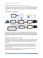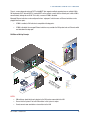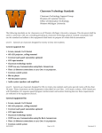
1
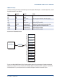
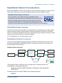
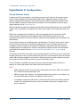
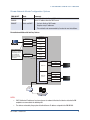
IP Considerations Guide for the
IT Professional
The specific patents that cover Crestron products are listed at patents.crestron.com.
Crestron, the Crestron logo, 3-Series, CaptureLiveHD, Core 3 UI, Crestron Connected, Crestron Fusion, Crestron Mobile Pro, Crestron Toolbox, DigitalMedia, DM, and Fusion RV are
trademarks or registered trademarks of Crestron Electronics, Inc. in the United States and other countries. Flash is either a trademark or registered trademarks of Adobe Systems
Incorporated in the United States and/or other countries. iPad is either a trademark or registered trademark of Apple, Inc. in the United States and/or other countries. Cisco is either a
trademark or registered trademark of Cisco Systems, Inc. in the United States and/or other countries. Microsoft and ActiveX are either trademarks or registered trademarks of Microsoft,
Inc. in the United States and/or other countries. Java is either a trademark or registered trademark of Oracle America, Inc. in the United States and/or other countries. Other trademarks,
registered trademarks and trade names may be used in his document to refer to either the entities claiming the marks and names or their products. Crestron disclaims any proprietary
interest in the marks and names of others. Crestron is not responsible for errors in typography or photography.
This document was written by the Technical Publications department at Crestron.
©2013 Crestron Electronics, Inc.
IP Considerations Guide for the IT Professional
Contents
Introduction
What is Crestron? ��������������������������������������������������������������������������������������������������������������������������������������1
What is a Control System?�������������������������������������������������������������������������������������������������������������������������������1
Why is it on our Network?��������������������������������������������������������������������������������������������������������������������������������1
Planning a Network with Crestron Devices
Isolate The Network�����������������������������������������������������������������������������������������������������������������������������������������2
VLAN Configuration������������������������������������������������������������������������������������������������������������������������������������������2
Listen Ports�����������������������������������������������������������������������������������������������������������������������������������������������������3
Connect Ports��������������������������������������������������������������������������������������������������������������������������������������������������4
IP Addressing���������������������������������������������������������������������������������������������������������������������������������������������������4
IPv6����������������������������������������������������������������������������������������������������������������������������������������������������������������� 4
Hostnames������������������������������������������������������������������������������������������������������������������������������������������������������4
Crestron Control Subnet
Configuration���������������������������������������������������������������������������������������������������������������������������������������������������5
Listen Ports�����������������������������������������������������������������������������������������������������������������������������������������������������6
IP Addressing���������������������������������������������������������������������������������������������������������������������������������������������������6
Hostnames������������������������������������������������������������������������������������������������������������������������������������������������������7
Security
Security Setup�������������������������������������������������������������������������������������������������������������������������������������������������8
Firewall Setup / Communication Across Multiple VLANs�����������������������������������������������������������������������������������8
DigitalMedia Network Considerations
DigitalMedia System Topology��������������������������������������������������������������������������������������������������������������������������9
DigitalMedia Ethernet Connectivity�������������������������������������������������������������������������������������������������������������������9
DigitalMedia IP Configuration
Private Network Mode������������������������������������������������������������������������������������������������������������������������������������ 10
Rapid Spanning Tree Protocol (RSTP)������������������������������������������������������������������������������������������������������������� 12
|
Doc. 4579D crestron.com
i
IP Considerations Guide for the IT Professional
Introduction
This design guide is intended to outline the requirements, best practices and preferred methods of implementing
Crestron® devices on enterprise level networks. The guide is focused on the concerns of the IT professional and
Crestron is dedicated to providing the most accurate and pertinent information. If after reading this document,
there are still concerns about deploying Crestron devices on the network, please contact Crestron True Blue
Support at 1-888-CRESTRON.
What is Crestron?
Crestron Electronics is the leading provider of control and automation systems for homes, offices, schools,
hospitals, hotels and more. A proven and trusted company with installations in facilities of technology leaders of
the world like Microsoft® and Cisco®, Crestron control systems are suited for the most mission-critical and secure
environments.
What is a Control System?
A control system is an appliance grade network-based device designed to control disparate devices and link
them together over an IP network. A control system issues commands and gathers data to and from other devices
based on user driven and automated events. Typically driving classroom and boardroom AV systems, a control
system turns on the display and sets the correct input on a touch screen, remote control or button panel (keypad).
Control systems can also interface with lighting and HVAC systems so when “PC” is selected, the lights dim to
an appropriate level for viewing computer images. Crestron control systems can be custom programmed or
configured. Any single button press or collection of data can trigger a number of events.
Why is it on my Network?
Traditionally control systems interface with devices via IR, RS-232, closed contacts and variable voltage. The
natural progression over the past years has moved toward IP based communication. Many devices have
implemented IP protocols for control, monitoring and management mainly because IP is more common and cost
effective to integrate.
Crestron systems were the first control systems to implement IP communication almost 15 years ago. Today,
Crestron offers some of the most advanced IP devices in the AV and lighting control industry. These systems can
be controlled, maintained, and monitored from anywhere there is an Internet connection. This greatly enhances the
ability to update and troubleshoot systems without the need to be physically on site.
|
Doc. 4579D crestron.com
1
IP Considerations Guide for the IT Professional
Planning a Network with Crestron Devices
Before deploying a Crestron system on a network, it is important to consider the guidelines defined in this section.
While there are many ways to configure an enterprise network, these best practices have been found to be the
most efficient and successful for Crestron devices.
Isolate the Network
Crestron devices should exist on a network separate from other device traffic. Other network activity can impact
the response time of Crestron devices and disrupt the user experience.
Unlike most other applications communicating over the LAN/WAN, Crestron users expect instant control and
feedback. In today’s world users want access to e-mail in minutes, Web pages in seconds, and expect a touch
screen to work instantaneously.
To ensure constant connection and accurate feedback, proprietary Crestron control communications uses a
heartbeat packet. Loss of round trip heartbeat packets indicate unreliable connections. This strict response
time and connectivity requirement ensures user confidence but is very latency sensitive. Therefore, Crestron
recommends setting up all Crestron devices on a dedicated (Crestron only) VLAN so that unnecessary traffic does
not interfere with the time sensitive packets between Crestron devices.
Deploying Crestron devices on a dedicated VLAN provides network access control in addition to username and
password authentication that are available on Crestron control systems.
VLAN Configuration
Whenever possible, all Crestron devices should be separated into their own VLAN. This allows for a smoother
operation of the control network and helps manage the infrastructure—resulting in a better user experience.
The following steps should be taken to ensure that Crestron devices can be managed effectively:
• If Crestron devices reside on multiple VLANs, static routes should be set up between VLANs on a router.
• DHCP requests should be forwarded to the appropriate VLAN with a Dynamic Host Configuration Protocol
(DHCP) server.
• Crestron ports should not be blocked for proper operation. For detailed information regarding what port
numbers are required, please consult the appropriate device manual.
• Some devices allow for streaming media content from the Internet. These devices should be allowed to
connect to the Internet if streaming is desired.
2
|
Doc. 4579D crestron.com
IP Considerations Guide for the IT Professional
Listen Ports
A Crestron control system listens to the following set of default ports. Not all ports are turned on by default; consult
the product manual for more details.
Port
21
23
80
161
443
41794
41795
41796
41797
Protocol
TCP
TCP
TCP
UDP
TCP
TCP/UDP
TCP
TCP
TCP
Service
FTP
Telnet
Web access
SNMP
Web access
Crestron over IP
Crestron console
Crestron over IP
Crestron console
Notes
3-Series® only
For user program interface and setup pages
Active with SSL enabled
Proprietary Crestron control communications
Requires proprietary management tool
Active with SSL enabled
Active with SSL enabled
Crestron over IP Communications
Other Crestron
Control System
Crestron Touch
Screens
Other Crestron
Peripherals
Crestron
Control System
Crestron over IP
Communication
ActiveX®
Web Interface
Java®
Web Interface
Flash®
Web Interface
Fusion RV®
User Program
via SDK
Core 3 UITM
XPanel
for Computers
The user can add multiple listeners to the Crestron control system via the user program. Crestron recommends
performing a security scan on the control system without a program and then test with a program. It can then be
easily determined if any security breaches are created by the program loaded in the control system.
|
Doc. 4579D crestron.com
3
IP Considerations Guide for the IT Professional
Connect Ports
A Crestron control system listens to the following set of default ports. Not all ports are turned on by default; consult
the product manual for more details.
Port
21
25
42
53
67/68
80
161/162
443
41794
41796
Protocol
TCP
TCP
TCP/UDP
UDP
UDP
TCP
UDP
TCP
TCP/UDP
TCP
Service
FTP
SMTP
WINS Access
DNS Access
DHCP Configuration
HTTP
SNMP
HTTPS
Crestron over IP
Crestron over IP
Notes
3-Series only
Only if enabled in control program
3-Series only
3-Series only
Proprietary Crestron control communications
Active with SSL enabled
IP Addressing
In most installations Crestron recommends configuring devices with static IP addresses to avoid DNS issues.
Especially in large corporate or university environments, using static or reserved DHCP aids in managing devices
and avoids potential DNS issues.
However, DHCP should be used when devices are connected to a Crestron Control Subnet. Refer to the Crestron
Control Subnet section for more information.
IPv6
All Crestron Ethernet devices can exist on an IPv6 network.
Hostnames
Crestron best practices are to configure DNS and DHCP servers to allow hostnames to resolve via option 81 or
option 12.
4
|
Doc. 4579D crestron.com
IP Considerations Guide for the IT Professional
Crestron Control Subnet
The Crestron Control Subnet is a gigabit Ethernet network dedicated to Crestron devices making system updating
and troubleshooting faster. This feature is available on select 3-Series control systems such as the PRO3 and AV3.
The subnet ports provide seamless connectivity to the network, requiring just one IP address for the entire Crestron
system. This enables better all-around performance while maintaining the integrity of the IT network.
Crestron installers can access devices within the subnet via the hostname using Crestron Toolbox™ software. This
makes it easier to upload touch screen projects, firmware, or access other functions.
Configuration
All Crestron Ethernet devices should be connected to the Control Subnet except for the devices that provide
streams to the LAN such as the security cameras, CaptureLiveHD™ system devices, and Network Video Streamer.
These devices should be connected to the LAN and not to the Control Subnet.
There is no enforced limit to the number of devices that are supported on the Control Subnet. While the subnet
mask provides an upper limit, Ethernet best practices should be followed to determine the appropriate number of
devices for the network.
Crestron devices should be set to be in DHCP mode which allows the Control Subnet DHCP server to assign
addresses. Unlike on a public network, Crestron requires all devices on the Control Subnet to be DHCP. Reserved
DHCP leases can be set up on the Control Subnet. The Control Subnet cannot run in static mode. When on the
Control Subnet, DM® should be in Private Network Mode (PNM).
NOTES:
• Some DM streaming cards support two network connections. These streaming cards can reside in a
DM chassis on the Control Subnet, but their external network connections should be connected to the
corporate LAN.
• Do NOT plug the Control Subnet port into the corporate LAN. When another DHCP server is detected the
Control Subnet port is shut down.
• Only Crestron and Crestron Connected™ devices should be connected to the Control Subnet. Crestron
does not recommend connecting third-party devices to the Control Subnet.
• Two Control Subnet ports may not be connected together on the same network.
|
Doc. 4579D crestron.com
5
IP Considerations Guide for the IT Professional
Listen Ports
On the Control Subnet, the number of listen ports on the LAN changes. There are an additional 100 listen ports.
Crestron utilizes listen ports 64,000 to 64,099 as the range which can be changed. Listen ports are used for
Crestron configuration changes for Crestron devices on the Control Subnet and dynamically open and close.
Control Subnet Example
IP Addressing
Automatic Mode (Default)
In order to eliminate routing conflicts between the Control Subnet and the LAN, the Control Subnet IP address is
automatically set based on the LAN-side Ethernet configuration. Refer to the table below for more information on
Control Subnet IP addressing in automatic mode.
LAN
Class A
Class B
Class C
Control Subnet
Class B (172.22.0.0/16)
Class A (10.0.0.0/8)
Class B (172.22.0.0/16)
Manual Mode
There is usually no need to change the Automatic Settings and there is no conflict. If necessary, the user can set
the routing prefix for the Control Subnet manually. This should only be done if the LAN contains a network that
conflicts with the Control Subnet.
NOTE: If the routing prefix is set on the Control Subnet any reserved leases are erased and the control system no
longer checks for routing conflicts between the LAN and the control system. It is important that the user is familiar
with this procedure before proceeding.
6
|
Doc. 4579D crestron.com
IP Considerations Guide for the IT Professional
Set the Routing Prefix for the Control Subnet Manually:
1. From the Crestron Toolbox System Information Tool, select Functions | Ethernet Addressing. The “Ethernet
Addressing” window is displayed.
“Ethernet Addressing” Window
2. Select the Control Subnet tab.
3. Change the mode to Manual.
4. For Routing, enter the routing prefix in Classless Inter-Domain Routing (CIDR) notation.
NOTE: Only routing prefixes from /8 to /24 are accepted.
Examples:
• 10.0.0.0/8 is valid
• 10.0.0.1/8 is invalid, this is not a router prefix
Hostnames
Crestron recommends changing hostnames to meaningful names. The Control Subnet allows port forwarding
based on the hostname of the device.
|
Doc. 4579D crestron.com
7
IP Considerations Guide for the IT Professional
Security
The following security information is centered around Crestron control systems. For a list of control systems, refer
to the Crestron website.
Security Setup
• Define an administrator password – this guarantees that only authorized personnel can make changes
to the configuration of Crestron equipment.
• Enable SSL – this ensures that passwords are not sent clear-text over the network.
• Add passwords and passcodes – have a Crestron programmer add passwords/passcodes to the
sections of the user program that are related to configuration of third-party devices.
Firewall Setup / Communication Across Multiple VLANs
Crestron systems can be controlled remotely. For example, an iPad® running Crestron Mobile Pro® G on a 3G
cellular network can send commands to the control system to adjusts the lights. In another scenario, a centrally
located Crestron Fusion™ server requires communication across multiple networks in order to communicate with
all rooms.
These applications require the following ports to have access to the outside network:
Port
80
Protocol
TCP
Service
Web server
443
41794
TCP
TCP
Web server
Crestron over IP
Notes
Web pages can also be hosted via IIS or other
corporate Web server
For secure SSL access
Proprietary Crestron control communications
Additionally, Crestron control systems can be managed from any IP address locally or remotely. Programs and
firmware can be updated; diagnostic tests can be performed. For this communication, enable the following:
Port
41795
41797
8
Protocol
TCP
TCP
Service
Crestron console
Crestron console
Notes
Use if SSL is disabled
Use if SSL is enabled
|
Doc. 4579D crestron.com
IP Considerations Guide for the IT Professional
DigitalMedia Network Considerations
Most Crestron DigitalMedia™ devices are Ethernet devices. Ethernet traffic due to DM devices is relatively low. The
custom control system program that controls the DM system dictates how much bandwidth is needed.
DigitalMedia Certified Designers and Engineers
Every Crestron DM system should be designed by a DigitalMedia Certified
Designer (DMC-D) and commissioned by a DigitalMedia Certified Engineer (DMC-E).
Only Crestron certified engineers ensure that a system is properly installed and
configured to Crestron standards. The information in this design guide is intended
to explain basic DM IP addressing considerations. Consult with the DMC-E for further questions.
DigitalMedia System Topology
Each DM link (connection between two DM devices) embeds Ethernet so no additional wiring is needed to provide
network connectivity for third-party Ethernet products installed at the endpoints. To facilitate this, Crestron DM
devices have integrated managed Ethernet switches and exposed Ethernet ports. An Ethernet connection at the DM
switcher ensures network connectivity at all connected endpoints.
NOTE: DM endpoints refers to any DM transmitter or receiver.
DigitalMedia Ethernet Connectivity
In the scenario below, Ethernet connectivity is provided to all DM devices and third-party devices from the LAN
connections to the DM-MD6X6 and DM-MD8X8 switchers. This eliminates the need to run extra wiring to each
location to provide Ethernet connectivity.
DigitalMedia Ethernet Connectivity
DM-201-C
Transmitter
Blu-ray Player
DM-401-S
Transmitter
DM-RMC-200-C
Receiver
DM-MD8X8
Card-based
Switcher
DM-MD6X6
Switcher
LAN
Projector
DM-RMC-100-C
Receiver
Key
Ethernet
DM Link
The main Ethernet uplink to a DM system occurs at the DM switcher. The following switchers have
10/100/1000BaseT auto-negotiating uplink ports:
• DM-MD6X6, DM-MD6X4, DM-MD8X8, DM-MD16X16, DM-MD32X32, DMPS, DM-MD64X64,
DM-MD128X128
The following switchers have 10BaseT/100BaseTX auto-negotiating uplink ports:
• DM-MD6X1
|
Doc. 4579D crestron.com
9
IP Considerations Guide for the IT Professional
DigitalMedia IP Configuration
Private Network Mode
Previously every DM card and endpoint in an installation required its own IP address on the corporate network.
In 2012, Crestron introduced Private Network Mode to DM switchers. PNM greatly reduces the number of IP
addresses required for DM installations. Crestron recommends using PNM to manage Ethernet settings for DM
cards and endpoints connected to a DM switcher. Other methods are not recommended. For details on legacy
modes of operation, refer to Crestron Online Help.
PNM is not applicable to standalone installations involving directly-connected DM endpoints with no associated DM
switchers. In these installations each endpoint device needs its own IP address, either configured manually or via
DHCP.
PNM creates a completely private IP network for all DM cards and endpoints that are connected to the DM
switcher, effectively isolating them from the building network. PNM significantly streamlines home and
organizational infrastructures, conserving IP addresses, reducing costs and simplifying system management and
troubleshooting.
The only device that appears on the building network is the DM switcher. The switcher needs just one IP address,
which can either be set statically or assigned via the building’s DHCP server. In this mode, none of the cards
or endpoints are directly reachable via the network of the building; instead communication to these devices is
managed through the main DM switcher. The devices connected to the LAN ports found on many DM endpoints
remain visible to the network. Refer to the “Private Network Mode with Auxiliary Devices” on page 11 for an
illustration.
The main DM switcher CPU is the only device connected to both networks. That CPU may receive an instruction on
the public network such as from a Crestron control system and create a new instruction for a device on the private
network (DM card, blade or endpoint). At no time does an Ethernet packet from the public network traverse to the
private network and no private Ethernet packets may traverse to the public network.
For most installations, using PNM is the best practice because it does not heavily impact the network in a
corporate- or university-type setting. It also isolates traffic that is related to DM.
NOTES:
• PNM is enabled by default on all new units and is enabled upon system restore. PNM is only available in
PUF 2.40 (firmware package update file) or later.
• DMPS units require two IP addresses. The integrated control processor requires its own IP address, and
the integrated DM equipment (switcher, all endpoints) requires one more.
• If an endpoint is connected to a DM switcher its LAN connector must not be connected to the corporate
network. In this configuration these ports are only for connection to devices such as laptops, Blu-ray
players or projectors.
10
|
Doc. 4579D crestron.com
IP Considerations Guide for the IT Professional
Private Network Mode Configuration Options
PNM ON/OFF
PNM ON
PNM ON
PNM OFF
Mode
Static
DHCP
Static and DHCP
Comments
Assign 1 IP address to the main DM switcher
Takes 1 IP address from the DHCP server
• Can be in Static or DHCP mode
• Requires many IP addresses
• This method is not recommended by Crestron for most installations
Private Network Mode with Auxiliary Devices
DM-MD8X8
Inputs
10.0.0.151
DM-TX-100
PNM IP
DMC-CAT
DM-TX-201-C
DMC-C
PNM IP
PNM IP
2
DM-TX-201-S
DMC-S
3
DMC-HD
4
PNM IP
PNM IP
PNM IP
Devices attached to
Ethernet ports on DM
endpoints are connected
to the building network.
In this example, this
laptop receives an IP
address from the DHCP
server below.
1
DMC-DVI
5
DMC-VID-RCA-D
6
DMC-F
7
DMC-SDI
8
PNM IP
DM-TX-100-F
PNM IP
PNM IP
Outputs
1
DM-RMC-100
2
DM-RMC-100
PNM IP
DMCO-23
PNM IP
3
10.0.0.181
4
5
DM-RMC-100-S
6
DM-RMC-200-S
PNM IP
DMCO-45
7
(2) PNM IPs
PNM IP
DM-RMC-100-C
PNM IP
DM-RMC-200-C
8
PNM IP
10.0.0.187
10.0.0.10
LAN
DHCP Server
10.0.0.1
NOTES:
• DHCP distributed IP addresses have been chosen at random to illustrate that devices attached to DM
endpoints are connected to the building LAN.
• The devices enclosed by the gray box sit behind the one IP address assigned to the DM-MD8X8.
|
Doc. 4579D crestron.com
11
IP Considerations Guide for the IT Professional
Multiple DigitalMedia Switchers using Private Network Mode
When two or more switchers are connected by way of DM links, they are considered cascaded. Each DM switcher
in a cascaded system must be configured with a unique System ID. This prevents IP conflicts among DM devices
on the private network. In the illustration below, only one IP address per switcher is required from the building
network.
Multiple DM Switchers using PNM Example
Control System
Corporate LAN
Key
DM Link (Internal DM Network)
Corporate LAN
Corporate LAN Tunnel through DM
DM Transmitter
DM Switcher
SystemID: 01
DM Receiver
DM Switcher
SystemID: 02
DM Receiver
(Shaded area represents
closed DM network)
These DM switchers are on the DM
Private Network. They must remain
attached to the corporate LAN.
NOTE: The SystemID can range from 01 to 64, and must be uniquely set for each DM switcher. By default, the
SystemID is set to 01. The ID can be set via the front panel, the SIMPL Windows program or the System Info tool in
Crestron Toolbox. Each DM switcher must be directly connected to the corporate LAN; one DM switcher cannot
receive Ethernet via another DM switcher and each DM switcher must receive an IP address from the corporate
LAN.
Rapid Spanning Tree Protocol (RSTP)
Since DM devices embed Ethernet in every link, a valid AV configuration can create network loops, such as routing
two AV signals from one switcher to another switcher. To eliminate any network looping problems, DM products
implement IEEE 802.1w RSTP. With PNM enabled, the DM switcher manages the DM Ethernet links to prevent
network loops.
DM products transmit Bridge Protocol Data Units (BPDU) per the RSTP specification. With PNM enabled, BPDUs
are isolated to the private network and are not visible to the corporate network. RSTP is not enabled on
user-accessible LAN connectors. To prevent network loops, endpoints should not be connected to the corporate
LAN in this configuration.
By default, every DM switcher ships with PNM and RSTP enabled. If PNM is disabled, RSTP remains enabled.
If required disable RSTP and manage Ethernet ports manually.
12
|
Doc. 4579D crestron.com
IP Considerations Guide for the IT Professional
There is a more advanced version of RSTP called MSTP that supports multiple spanning trees on multiple VLANs.
DM implements RSTP, but not MSTP. If running MSTP on the network, ensure that the network port in which DM is
connected only belongs to one VLAN. This is only a concern if PNM is disabled.
Managed Ethernet switches can be configured to have “edge ports” which means no Ethernet switches can be
plugged into these ports.
• If PNM is enabled, a DM switcher is compatible with edge ports.
• If PNM is disabled, the managed Ethernet switches may consider the DM system to be an Ethernet switch
and shut down the edge port.
DM Ethernet Wiring Example
LE
CE
EN
ER
F
ON
B
TA
LOCAL
MONITOR
C
LAPTOP
ernet
Eth
I
M
HD
P
TU
DIO
SE
AU
SB
B
U
T
OU
O
DI
AU
DM
IN
6
DM
O
DI
AU
T
MI
OU
HD
M
MI
R
C-HD
DM
DM
IN
CO
HD
MI
-C
01
OU
HD
4
D
D8
A
DI
L ME M
O
DI
AU
OU
A
DI
L ME M
-DSP
AT
C-C
24
24
-DSP
AT
C-C
24
OU
DM
TA
GI
DI
D
1
DM
T
DM
TA
GI
DI
D
T
MI
HD
24
AB
G
AB
G
AB
G
AB
EI
G
EI
G
EI
G
G
OU
M
E IN
DM
T
OU D
UTS
TP
OU
24
24
24
24
DM
AB
G
AB
G
+
UTSDMD
G
EI
G
DM
T
G
EI
DM
A
4.0
V~
Hz
50
0-2
10 50/60
G
EI
+
PO
M
6
OU
+
MI
HD
D
- G
D
-
HD
4
7
N
LA
e
lM
ita
g
Di
, RO
IGH,
0764
INC.
N
STRO
CRE
LAN
N
LA
PC
RESET
MI
HD
PW
UP
SET
DM
DM
2G
M
D
GN
TX M
CO
RX
S
RT
S
CT
-2
I
M
HD ol
r
t
on
DM
PROJECTOR
T
SE
C
S 1 IR
G
S 2
S
N
LA
DM
O
RO
-C
00
-1
MC
-R
DM
R
LE
OL
TR
M
I
BLU-RAY
P
TU
SE
AUDIO
SYSTEM
IN
RE
T
OU
HD
dio
M
-R
HD
00
DM
N
LA
Au
10
C-
MI
PC
IN
DM
K
LIN
X
-T
C
0-
CONTROL
SYSTEM
MI
HD
IN
R
NJ
LE
CK
ICS
ON
TR
EC
EL
I
M
HD
8G
DM Con
Sw nect
itc
he Ever
r to y
LA
DM
N
8G
-53
O
MC
3
dia
T
OU
OU
8
-
MI
7
MI
HD
T
M
MI
MI
HD
- G
EI
R
PW C
VD
24 5A
0.7
TP
OU
HD
PO
M
D
G
G
AB
E IN
+
5
AB
G
EI
T
MI
HD
2
-T
M
D
3
T
OU
2
X-
8
1
O
DI
AU
T
SE
RE
7
HD
M
MI
M
D
X8
B
US
HID
C
1ER
20
NT
XCE
-T
DM TER
U
MP
T
OU
L
D
B HI
US
2
T
-M
DIO
AU
IN
US
C-C
DM
E IN
PO
D
IN
MI
HD
D
B HI
5
R
L
RG
N
CO
V
24 MAX
5A
0.7
Do
Re NOT
cei
C
ve onn
r to ec
LA t
N
TM
Color Key
Control
Audio
HDMI
LAN
DigitalMedia
DM 8G
Ethernet
N
LA
NOTES:
• DM switchers should be the only devices in the DM system connected to the LAN
• Ensure that the System ID of each DM switcher in the system is unique
• Do not connect room controllers or transmitters to the LAN
|
Doc. 4579D crestron.com
13
Crestron World Headquarters
15 Volvo Drive
Rockleigh, NJ 07647
Tel: 888.CRESTRON
Fax: 201.767.7676
crestron.com
Refer to the listing of Crestron worldwide offices on the Crestron website
(www.crestron.com/offices) for assistance within a particular geographic region.
Printed in USA Doc. 4579D 11/13