1
Brant Radiant Heaters, Ltd.
AVS Series
Gas-Fired Infrared Quad Tube Heater
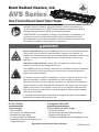
WARNING: Improper installation, adjustment, alteration, service or maintenance can
cause property damage, injury or death. Read the installation, operating and maintence
instructions thoroughly before installing or servicing this equipment.
AVERTISSEMENT. Une installation, un réglage, une modification, une réparation ou un
entretien incorrect peut entraîner des dommages matériel, des blessures ou la mort.
lisez attentivement les instructions d’installation, de fonctionnement et d’entretien avant
de procéder à l’installation ou à l’entretien de cet équipement.
!
WARNING
Not for residential use! This heater is NOT approved for use in any residential application.
This includes, but is not limited to, attached garages, solariums, living quarters, etc.
Installation in residential spaces may result in property damage, asphyxiation, serious injury
or death. Consult your local fire marshall and/or insurance carrier if unsure of your
application.
Interdit pour usage résidentiel. Ne pas utiliser cet appareil à la maison, dan les
chambres à coucher, dan les harages attenants, etc.
This is NOT an explosion proof heater. Where there is a possibility of exposure to flammable
vapors, consult the local fire marshall, the fire insurance carrier and other authorities for
approval of proposed installation.
Cet émetteur n’est pas un appareil antideflagrant. Lorsqu’il y a risque de contact avec des
vapeurs inflammables, consulter le commissaire local des incendies, la compagnie
d’assurance incendie ou tout autre authorité compétente pour approbation de l’installation.
Storage of gasoline or other flammable vapors and liquids in the vicinity of this or any other
appliance may result in fire or explosion. Do not store or use gasoline or other flammable
vapors and liquids in the vicinity of this or any other appliance. Always maintain published
clearance to combustibles.
Il est interdit d’utiliser des liquides inflammables ou degagent des vapeors inflammabled a
proximaite de tout appareil fonctionnant au gaz.
For Your Safety
Consignes De Sécurité
If you smell gas:
Si vous sentez une odeur de gaz:
• Open windows.
• Ouvrez les fenêtres.
• Do not touch any electrical switch.
• Ne touches pas aux interrupters électriques.
• Extinguish any open flame.
• Éteignez toute flamme nue.
• Do not try to light any appliances.
• Contactez immediatement votre compagnie de gaz.
• Immediately call your gas supplier from a
neighbours phone.
Keep these instructions for future reference.
LIOBRHAVS 0911
1.0 Introduction • Table of Contents
AVS Series
Contents
1.0 Introduction . . . . . . . . . . . . . . . . . . . . . . . . . . . . . . . . . . . . . . . . . . . . . . . . . . . . . . . . . . . . . . 3
Overview . . . . . . . . . . . . . . . . . . . . . . . . . . . . . . . . . . . . . . . . . . . . . . . . . . . . . . . . . . . . 3
Heater Components . . . . . . . . . . . . . . . . . . . . . . . . . . . . . . . . . . . . . . . . . . . . . . . . . . . 3
Specifications . . . . . . . . . . . . . . . . . . . . . . . . . . . . . . . . . . . . . . . . . . . . . . . . . . . . . . . . 3
Safety Labels and Their Locations . . . . . . . . . . . . . . . . . . . . . . . . . . . . . . . . . . . . . . . . 4
2.0 Safety . . . . . . . . . . . . . . . . . . . . . . . . . . . . . . . . . . . . . . . . . . . . . . . . . . . . . . . . . . . . . . . . . . . 6
Warning Symbols . . . . . . . . . . . . . . . . . . . . . . . . . . . . . . . . . . . . . . . . . . . . . . . . . . . . . 6
Applications . . . . . . . . . . . . . . . . . . . . . . . . . . . . . . . . . . . . . . . . . . . . . . . . . . . . . . . . . . 7
Standards, Certifications and Government Regulations . . . . . . . . . . . . . . . . . . . . . . . . 7
Clearance to Combustibles . . . . . . . . . . . . . . . . . . . . . . . . . . . . . . . . . . . . . . . . . . . . . . 8
3.0 Installation . . . . . . . . . . . . . . . . . . . . . . . . . . . . . . . . . . . . . . . . . . . . . . . . . . . . . . . . . . . . . . . 10
Design Considerations and Prechecks . . . . . . . . . . . . . . . . . . . . . . . . . . . . . . . . . . . . . 10
Recommended Mounting Heights and Coverages . . . . . . . . . . . . . . . . . . . . . . . . . . . . 11
Application Guidelines. . . . . . . . . . . . . . . . . . . . . . . . . . . . . . . . . . . . . . . . . . . . . . . . . . 11
Heater Packaging . . . . . . . . . . . . . . . . . . . . . . . . . . . . . . . . . . . . . . . . . . . . . . . . . . . . . 12
Heater Mounting Requirements and Weights . . . . . . . . . . . . . . . . . . . . . . . . . . . . . . . . 12
Heater Assembly . . . . . . . . . . . . . . . . . . . . . . . . . . . . . . . . . . . . . . . . . . . . . . . . . . . . . . 13
Preparing Points for Hanging . . . . . . . . . . . . . . . . . . . . . . . . . . . . . . . . . . . . . . . . . . . . 14
Hanging Pre-Assembled Unit . . . . . . . . . . . . . . . . . . . . . . . . . . . . . . . . . . . . . . . . . . . . 16
Venting. . . . . . . . . . . . . . . . . . . . . . . . . . . . . . . . . . . . . . . . . . . . . . . . . . . . . . . . . . . . . . 18
Combustion Air Requirements . . . . . . . . . . . . . . . . . . . . . . . . . . . . . . . . . . . . . . . . . . . 23
Gas Supply . . . . . . . . . . . . . . . . . . . . . . . . . . . . . . . . . . . . . . . . . . . . . . . . . . . . . . . . . . 25
Electrical Requirements and Wiring Diagrams . . . . . . . . . . . . . . . . . . . . . . . . . . . . . . . 28
4.0 Operation . . . . . . . . . . . . . . . . . . . . . . . . . . . . . . . . . . . . . . . . . . . . . . . . . . . . . . . . . . . . . . . . 32
Start-up and Shutdown Procedures . . . . . . . . . . . . . . . . . . . . . . . . . . . . . . . . . . . . . . . 32
Sequence of Operation . . . . . . . . . . . . . . . . . . . . . . . . . . . . . . . . . . . . . . . . . . . . . . . . . 33
5.0 Maintenance . . . . . . . . . . . . . . . . . . . . . . . . . . . . . . . . . . . . . . . . . . . . . . . . . . . . . . . . . . . . . . 34
Troubleshooting Guide . . . . . . . . . . . . . . . . . . . . . . . . . . . . . . . . . . . . . . . . . . . . . . . . . 34
Heater Components and Parts List . . . . . . . . . . . . . . . . . . . . . . . . . . . . . . . . . . . . . . . . 38
Routine Inspection. . . . . . . . . . . . . . . . . . . . . . . . . . . . . . . . . . . . . . . . . . . . . . . . . . . . . 40
Maintenance Log. . . . . . . . . . . . . . . . . . . . . . . . . . . . . . . . . . . . . . . . . . . . . . . . . . . . . . 41
Limited Warranty Terms and Conditions . . . . . . . . . . . . . . . . . . . . . . . . . . . . . . . . . . . . 43
Kit Contents Check List . . . . . . . . . . . . . . . . . . . . . . . . . . . . . . . . . . . . . . . . . . . . . . . . . 44
2
1.0 Introduction • Overview • Heater Components • Specifications
AVS Series
1.0 Introduction
Overview
The intent of this manual is to provide information regarding safety, design guidelines, installation,
operation and maintenance of the radiant heater. You must read and understand the instructions and all
safety warnings before installing the radiant heater.
Heater Components
Prior to installation, verify that the heater’s gas type and voltage (as listed on the rating plate) match
that of your application. Also verify that you have received all heater components included with your
tube heater. Refer to page 44 for a list of the kit contents for your Series heater. Materials not included
in the heater kit contents (e.g., screws, vent material, terminals, etc.) are the responsibility of the
installer. Notify your product representative or Brant Radiant Heaters Limited of any discrepancy or
missing kit contents prior to installing unit.
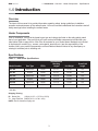
Specifications
Chart 1.1 • AVS Series Specifications
Model Number
Gas Type
BTU/h
Recommended
Mounting
Heights*
AVS-40N
Natural Gas
40,000
6 to 7 ft.
103 lbs.
106”
AVS-40P
Propane
40,000
6 to 7 ft.
103 lbs.
106”
AVS-60N
Natural Gas
60,000
6 to 8 ft.
103 lbs.
106”
AVS-60P
Propane
60,000
6 to 8 ft.
103 lbs.
106”
AVS-80N
Natural Gas
80,000
6 to 9 ft.
103 lbs.
106”
AVS-80P
Propane
80,000
6 to 9 ft.
103 lbs.
106”
Unit Weight
Overall Unit
Length
* Recommended mounting heights are provided as a guideline. Actual conditions may dictate variations from
this data.
Shipping / Boxing:
B = Burner Box
(15#) & (31.5”L x 17.5”W x 15.5”H)
T = Large Tube Box (88#) & (91”L x 31”W x 14”H)
NOTE: See Kit Contents on page 44.
3
1.0 Introduction • Safety Labels and Their Locations
AVS Series
WARNING
!
Improper installation, adjustment, alteration, service or maintenance can cause
property damage, serious injury or death. Read and understand, the installation,
operating and maintenance instructions thoroughly before installing or servicing this
equipment. Only trained, qualified gas installation and service personnel may install or
service this equipment.
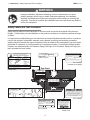
Safety Labels and Their Locations
Safety warning labels must be maintained on the tube heater and should be replaced if they become
illegible. Contact either your local distributor or the product manufacturer for obtaining replacement signs
or labels.
It is important to provide warnings to alert individuals to potential hazards and safety actions. In locations
used for the storage of combustible materials, post a placard “specifying the maximum permissible
stacking height to maintain the required clearances from the heater to the combustibles” near the heaters
thermostat or in absence of such thermostats in a conspicuous location. Contact Brant Radiant Heaters
Limited or an authorized dealer for Clearance Safety Limit Signs or for Clearance Safety Limit Tags (one
tag is provided with each heater).
Air Meterin
erin
rin Orifi e
T REMOV
REM
OVE
E
DO NOT
REMOVE
TP-3014
SAMPLE
MPLE
RE-VERBER-RAY LOW INTENSITY INFRARED HEATER
RADIATEUR A INFRAROUGE A FAIBLE INTENSITE
FOR INDOOR INSTALLATION ONLY. NOT FOR USE IN RESIDENTIAL DWELLING.
MODEL /MODELE NO.
INPUT BTU/H
80,000
AVS-80P
PL
VOLTS A.C.
MANIFOLD PRESSURE
120~60Hz
10.0” WC
STARTING AMPS.
MIN. INLET PRESSURE
1.5
RUNNING AMPS.
1.1
ALTITUDE:
0 - 4,500 FT
M
SA
110” WC
ORIFICE SIZE
#19 D.M.S
ANSI Z83.20b - 2011 CSA 2.32b - 2011 Low - Intensity Infrared Htr.
ANS Z83.20b - 2011 CSA - 2011 Low - Intensity Infrared Htr.
BRANT RADIANT HEATERS LIMITED
34 SCOTT AVE., PARIS, ONTARIO
TEL: 1-519-442-7823 WWW.BRANTRADIANT.COM
FOR USE WITH
E
3
$
""%
;~
!
Z`[ !Z`[
'
!
!
"
Air Metering Orifice
PROPANE GAS
>qX
qX{
F/N: LLAC
INSTALLATION À L’EXTÉRIEUR SEULEMENT. NE PAS INSTALLER DANS UN LOGEMENT.
HEATER TYPE
C1
k\>
@
k>
\
VERSION
3/11
>F!;!
!
?F
?~?!!~?$!$?
!?F
!^!+!
?
MIN. MOUNTING ANGLE:
0 DEGREES
F/N: LLTB035
(Located on top panel)
MAX. MOUNTING ANGLE:
45 DEGREES
FOR INDOOR USE
SERIAL NO.
0870 XXXX XXXX 0001
Rear Panel
Rating Plate
J
X
JZ[
Z>
\
RADIATEUR A INFRAROUGE A FAIBLE INTENSITE
>Z>
[
]
MODEL /MODELE NO.
INPUT BTU/H
FOR USE WITH
80,000
AVS-80P
PROPANE GAS
VOLTS A.C.
MANIFOLD PRESSURE
120~60Hz
10.0” WC
STARTING AMPS.
MIN. INLET PRESSURE
1.5
110” WC
RUNNING AMPS.
ORIFICE SIZE
1.1
#19 D.M.S
HEATER TYPE
VERSION
@
MIN. MOUNTING ANGLE:
^
MAX. MOUNTING ANGLE:
_`
ALTITUDE:
0 - 4,500 FT
ANSI Z83.20b - 2011 CSA 2.32b - 2011 Low - Intensity Infrared Htr.
ANS Z83.20b - 2011 CSA - 2011 Low - Intensity Infrared Htr.
BRANT RADIANT HEATERS LIMITED
34 SCOTT AVE., PARIS, ONTARIO
TEL: 1-519-442-7823 WWW.BRANTRADIANT.COM
FOR INDOOR USE
SERIAL NO.
0870 XXXX XXXX 0001
$
""%
!
'
+
''
;
!<
>
='
9%;<#&">+,%?#
;
?
!
@F
"#$%&#'()+,,+&7#'(9%;#<#&"
?
J
=%&"##,@=&"#?'#&#+%
!
"
$
""%
!
'
+
''
;
!<
>
='
9%;<#&">+,%?#
;
?
!
@F
"#$%&#'()+,,+&7#'(9%;#<#&"
?
J
=%&"##,@=&"#?'#&#+%
F/N: LLTB036
4
F/N: LLTB014
Mount Level
F/N: LLTB037
1.0 Introduction • Safety Labels and Their Locations
AVS Series
AVS Series Internal Block Wiring Diagram
?$F>
ZXF
{X
?$!F
@
@
@
@
@
ZX`[
$!F?+!^!
@
!++!
+$
@
@
Z
?
|[?}
+Z
+
@
;F>?+$
>$
|[?}!
>
!
?;
F$!
>$
>?;
>?;
!
>
F^+?+!
HOT
F^+?+!
120V
NEUTRAL
EARTH
+?>\+$F>
>F+F
+F!>?$!+
Electrical Label
(Located inside service panel)
F/N: LLLOGO11
Logo Label
- 120V HEATER INPUT -
F/N: LLV3EP1
FIRE HAZARD. A
,
RIS UE D INCENDIE.
,
S
CLEARANCE TO COMBUSTIBLES in. and
X@| & 7<
_^q^^^
&
7<
X}
X
[
&
&
& 7<
7<
7<
`_ ^_
^q^^^
^
`_
__ _^
^
`_ ^_
^q^^^
^
`_
__ _^
^
`_ ^_
^
`_
__ _^
^
.
V
END VIEW
V A
S
S
~;
[]
"
SIDE VIEW
PAS
,
,
$
\
"
"
"
"
"
"
;
F"
"
$Z
'
'
P
SIDE VIEW
S
,
,
PAS
P
END VIEW
,
,
-
,
$
$
"
"
'
"
?
>
|?F][`F?+Z}
,
sP
s
sA
Right Panel
S
,
PA
A S
,
F
"["`ZXXX@$`"
,A S
PA 88A
,A S
PA 0A
,A S
PA 0
Left Panel
FIRE HAZARD. A
,
RIS UE D INCENDIE.
,
S
CLEARANCE TO COMBUSTIBLES in. and
X@| & 7< &
7<
X
[
&
7<
X}
&
& 7<
7<
.
V
END VIEW
V A
_^q^^^ ^ `_ __ _^ ^ `_ ^_
^q^^^ ^ `_ __ _^ ^ `_ ^_
S
S
^q^^^ ^ `_ __ _^ ^ `_ ^_
~;
[]
"
SIDE VIEW
PAS
,
,
$
\
"
"
"
"
"
"
;
F"
"
$Z
'
'
P
SIDE VIEW
S
,
,
PAS
P
END VIEW
,
,
-
,
$
$
"
"
'
"
?
>
|?F][`F?+Z}
,
sP
s
sA
S
,A S
PA 88A
,A S
PA 0A
,A S
PA 0
,
PA
A S
,
F
"["`ZXXX@$`"
F/N: LLTCL013: Clearance to
Combustibles and Gas Data Label
5
F/N: LLV3EP17
2.0 Safety • Warning Symbols
AVS Series
2.0 Safety
!
WARNING
Improper installation, adjustment, alteration, service or maintenance can cause
property damage, serious injury or death. Read and understand, the installation,
operating and maintenance instructions thoroughly before installing or servicing this
equipment. Only trained, qualified gas installation and service personnel may install or
service this equipment.
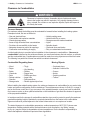
Warning Symbols
Safety is the most important consideration during installation, operation and maintenance of the tube
heater. You will see the following symbols and signal words when there is a hazard related to safety or
property damage.
!
!
WARNING
Warning indicates a potentially hazardous situation
which, if not avoided, could result in death or injury.
CAUTION
Caution indicates a potentially hazardous situation
which, if not avoided, could result in minor or
moderate injury.
Notice indicates a potentially hazardous situation
which, if not avoided, could result in property
damage.
NOTICE
!
CAUTION
Children and adults should be alerted to the hazards of high surface temperatures and should stay away
to avoid burns or clothing ignition.
Young children should be carefully supervised when they are in the same space as the heater.
Clothing or other flammable materials should not be hung from the heater, or placed on or near the heater.
Any guard or other protective device removed for servicing the heater must be replaced prior to operating
the heater.
Installation and repair should be done by a qualified service person. The heater should be inspected
before use and at least annually by a qualified service person. More frequent cleaning may be required
as necessary. It is imperative that the control compartment, air passageways and burner(s) of the heater
be kept clean.
6
2.0 Safety • Applications • Standards, Certifications and Regulations
AVS Series
Applications
This is not an explosion proof heater. No tube heater may be used in a Class 1 or Class 2 Explosive
Environment. Consult your local fire marshall, insurance carrier and other authorities for approval if the
proposed installation is in question.
Agricultural Applications
Unless otherwise indicated, tube heaters are designed and certified for use in agricultural buildings,
such as poultry houses, dairy parlors and swine houses. For maximum safety, the building must be
evaluated for potential problems before installing the heating system. A critical safety factor to consider
before installation is the clearance to combustibles.
!
WARNING
Not For Residential Use. Do not use this heater in the home, sleeping quarters,
attached garages, etc. Installation of a commercial tube heater system in residential
indoor spaces may result in property damage, serious injury or death.
Standards, Certifications and Government Regulations
Installation of this tube heater must conform with all applicable local, state and national specifications,
regulations and building codes. Contact the local building inspector and/or fire marshall for guidance.
In the absence of local codes, the installation must conform to the latest edition of:
United States: National Fuel Gas Code, ANSI Z223.1 (NFPA 54).
Canada: CAN/CGA B149.1, Canadian Electrical Code C22.1
7
2.0 Safety • Clearance to Combustibles
AVS Series
Clearance to Combustibles
!
WARNING
Placement of explosive objects, flammable objects, liquids and vapors
close to the heater may result in explosion, fire, property damage, serious
injury or death. Do not store or use explosive objects, liquids and vapors in
the vicinity the heater.
Common Hazards:
For maximum safety the building must be evaluated for hazards before installing the heating system.
Examples include, but are not limited to:
•
•
•
•
•
•
•
Gas and electrical lines
Combustible and explosive materials
Chemical storage areas
Areas of high chemical fume concentrations
Provisions for accessibility to the heater
Adequate clearances around air openings
Combustion and ventilating air supply
•
•
•
•
•
•
•
Vehicle parking areas
Vehicles with lifts or cranes
Storage areas with stacked materials
Lights
Sprinkler heads
Overhead doors and tracks
Dirty or contaminated environments
A critical safety factor to consider before installation is the clearances to combustibles. Clearance to
combustibles is defined as the minimum distance you must have between the tube surface, or reflector,
and the combustible item. Considerations must also be made for moving objects around the tube heater.
The following is a partial list of items from which to maintain clearances:
Combustible/Degrading Items:
Moving Objects:
•
•
•
•
•
•
•
•
•
•
•
•
•
•
Wood
Paper
Fabric
Chemicals
Paint
Parked vehicles
Gasoline
Storage racks
•
•
•
•
•
•
•
•
Tri-ply
Vinyl banding
Plastics
Fogger lines
Flexible gas lines
Auger lines
Feed pans/lines
Drinker nipples/nylon lines
Overhead doors
Vehicles & vehicle lifts
Cranes
Hoists
Catching machine
Trailers
When installing the radiant heating system, the minimum clearances to combustibles for your series tube
heater and system configuration must be maintained. These distances are shown in Chart 2.1 on page 9
and on the burner control box. If you are unsure of the potential hazards, consult your local fire marshall,
fire insurance carrier or other qualified authorities on the installation of gas fired tube heaters for approval
of the proposed installation.
In locations used for the storage of combustible materials, signs must be posted to specify the maximum
permissible stacking height to maintain the required clearances from the heater to the combustibles.
Signs must either be posted adjacent to the heater’s thermostat or in a conspicuous location.
The stated clearance to combustibles represents a surface temperature of 90°F (32°C) above room
temperature. Building materials with a low heat tolerance (such as plastics, vinyl siding, canvas,
tri-ply, etc.) may be subject to degradation at lower temperatures. It is the installer’s responsibility to
assure that adjacent materials are protected from degradation.
8
2.0 Safety • Clearance to Combustibles
AVS Series
!
WARNING
Failure to comply with the stated clearances to combustibles may result in
personal injury, property damage and/or death.
Failure to mount the appliance level may result in personal injury, property
damage and/or death.
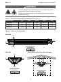
Chart 2.1 • Clearance to Combustibles in Centimeters (see Figure 2.1)
Model Number
Top
Sides
Below
Back
End
AVS-40 [N, P]
25.4
91.44
101.6
15.24
30.48
AVS-60 [N, P]
25.4
91.44
101.6
15.24
30.48
AVS-80 [N, P]
25.4
91.44
101.6
15.24
30.48
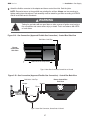
Figure 2.1 • Clearance to Combustibles
SIDE VIEW
Top
End
Back
Mount Heater Level
- Front to Back -
Below
END VIEW
BACK VIEW Showing Pitched Roof Installation
Top
Side
Side
10”
36”
36”
Below
Mount Heater Level
- Side to Side -
Mount Heater Level
- Side to Side -
9
3.0 Installation • Design Considerations and Prechecks
AVS Series
3.0 Installation
!
WARNING
Improper installation, adjustment, alteration, service or maintenance can cause property
damage, serious injury or death.
Read and understand, the installation, operating and maintenance instructions
thoroughly before installing or servicing this equipment.
Only trained, qualified gas installation and service personnel may install or service this
equipment.
Design Considerations and Prechecks
Placement of infrared heaters is influenced by many factors. Aside from safety factors, considerations
such as the number of heater or vent elbows that are allowed, maximum vent lengths, ducting of
combustion air and combining exhaust vents are a few examples. All installation manuals, along with
national, state, provincial and local codes, address these issues. It is critical that you read, understand
and follow all guidelines and instructions.
To ensure a properly designed heating system, a layout should be developed for the correct placement of
the heating appliance, vents and combustion air intake ducts. Inspect and evaluate the mounting
conditions, vent locations, gas supply and wiring. Refer Chart 3.1 on page 11 for the recommended
mounting heights and coverages for the model being installed.
NOTE: When heated, materials high in hydrocarbons (solvents, paint thinner, mineral spirits,
formaldehydes, etc.) can evaporate. This may result in odors or fumes being emitted into the
environment. To correct this problem, clean the area and/or introduce additional ventilation. Heaters
installed and serviced in accordance with the installation manual do not emit odors into the environment.
IMPORTANT: Fire sprinkler heads must be located at an appropriate distance from the heater. This
distance may exceed the published clearance to combustibles as posted on the heater. Certain
applications may require the use of high temperature sprinkler heads or relocation of the heaters.
!
CAUTION
Sprinkler systems containing propylene glycol or other flammable substances are not to be used in
conjunction with this heater without careful consideration for and avoidance of potential fire or explosion
hazards. For further information consult NFPA 13.
10
AVS Series
3.0 Installation • Recommended Mounting Heights and Coverages • Application Guidelines
Chart 3.1 • Recommended Mounting Heights and Coverages*
Model No.
Input
BTU/h
Recommended
Mounting Height (ft.)
Approximate Coverage Area
(LxW)
AVS-40 [N,P]
40,000
6 to 7
22 x 24
AVS-60 [N,P]
60,000
6 to 8
24 x 28
AVS-80 [N,P]
80,000
6 to 9
26 x 32
NOTE: This chart is provided as a guideline. Actual conditions may dictate variation from this data.
*Factory recommended mounting heights and approximate coverages are listed as a guideline for
designing for total building heat. However, certain applications such as spot heating, freeze protection
and outdoor heating generally require additional heat per square foot to comfortably heat these areas.
Clearances to Combustibles must always be maintained (Chart 2.1; Page 9).
Figure 3.1 • Application Guidelines
Brood End
Non-Brood End
For houses 400 feet long by 40 to 50 feet wide
Brood End
Non-Brood End
For houses 500 feet long by 40 to 50 feet wide
Brood End
Non-Brood End
For houses 600 feet long by 50 to 66 feet wide
Chart 3.2 • Heater Spacing**
House Length
Approx. Distance
from End Wall and
from Curtain
Approx. Distance
Between Heaters
Brood End
10-20 Feet
31-37 Feet
Non-Brood End
35-45 Feet
57-63 Feet
Brood End
10-20 Feet
34-40 Feet
Non-Brood End
30-40 Feet
57-63 Feet
Brood End
10-20 Feet
46-52 Feet
Non-Brood End
25-35 Feet
37-43 Feet
House Width
400 Feet
40 to 50 Feet
500 Feet
40 to 50 Feet
600 Feet
50 to 66 Feet
** Layouts may vary depending on house style, size and climate.
11
3.0 Installation • Heater Packaging
AVS Series
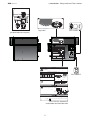
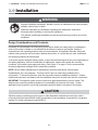
Heater Packaging
Heaters are made up of three pieces shipped in two boxes; the burner control box in the first box and the
emitter assembly and reflectors in the second box (see Figure 3.2).
Figure 3.2 • Heater Packaging • 2 Pieces
Burner Control Box
Emitter Assembly and Reflector Box
!
WARNING
Improper suspension of the tube heater may result in collapse and being crushed. Always
suspend from a permanent part of the building structure that can evenly support the total
force and weight of the heater.
Failure to maintain minimum clearance to combustibles may result in fire and/or explosion,
property damage, serious injury or death. Always maintain minimum clearances and post
clearance safety limit signs or the clearance safety tag where needed.
Chart 3.3 • Heater Mounting Requirements and Weights
Model
Overall Unit Length
Suspension Points
Shipping Weight
Chain Set Qty.
AVS-40 [N,P]
106”
3 or 4
103 lbs.
3
AVS-60 [N,P]
106”
3 or 4
103 lbs.
3
AVS-80 [N,P]
106”
3 or 4
103 lbs.
3
Shipping Dimensions:
B = Burner Control Box (15#) & (31.5”L x 17.5”W x 15.5”H)
T = Emitter Assembly and Reflector Box (88#) & (91”L x 31”W x 14”H)
NOTE: See Kit Contents on page 44.
12
3.0 Installation • Heater Assembly
AVS Series
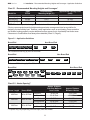
Heater Assembly
Assembly prior to hanging: With this method, the use of two saw horses or a raised table or bench
surface is beneficial (the emitter assembly and reflector box may also be used).
1
Lay the emitter assembly (TP-6082) across the horses or bench with the exchanger connection
hanging bracket extended out over the edge (See Detail ‘A’) NOTE: Use of the foam shipping blocks
will help protect the emitter coating and reflectors.
2
3
Install the tube flange gaskets (TP-6021B) onto the corresponding studs on the burner control box.
4
Install nine (9) 5/16 - 18 keps nuts provided, tightening evenly and torque to 20 ft-lb.
Align the nine (9) burner control box studs with the eight (8) holes located on the emitter plates and
the one (1) hole on the exchanger connection hanging bracket.
Reflector Sub-Assembly
1
2
On a flat surface, lay out two reflectors (TP-6088) parallel to each other.
Place U-end reflector end cap (TP-6084A) at one end and burner reflector end cap (TP-6085A) at the
opposite end with the “over/under tabs” facing the reflector.
3
Move the reflector end caps into the reflector ends while aligning the “over tabs” (larger tabs with
holes) over the top of the reflector and the “under tabs” (smaller tabs with no holes) under the reflector
(see Detail B). This can be achieved by squeezing the reflector slightly to fit within the end cap.
4
Properly secure reflector end caps to reflectors using #8-1/2” screws (TP-62) through the hole into the
reflector, being careful not to strip.
5
Repeat process with the remaining two reflectors.
Figure 3.3 • Heater Assembly
DETAIL ‘A’
Exchanger Connection
Hanging Bracket
NOTE: Cut foam
1/4” from dip
Tabbed
End
Burner
Control Box
Tube Flange Gasket
x2 (TP-6021B)
DETAIL ‘B’
Emitter Plates
Emitter
Assembly
(TP-6082)
Burner Reflector
End Cap
(TP-6085A) x2
Note: Install last.
See page 14.
Reflector (TP-6088) x4
Vent Adapter Fitting
(TP-6080)
Vent Pipe
(TP-6075)
U-End Reflector End Cap (TP-6084A) x2
Vent Cap
(WVE-GALV)
13
3.0 Installation • Heater Assembly • Preparing Points for Hanging
AVS Series
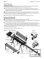
Installing the Reflector Assembly
NOTE: Prior to installing the reflector, relocate the saw horses to support the burner control box and the
tubes beneath the u-end reflector.
1
Align the reflector end cap holes (2) with the corresponding burner control box studs (see Detail
‘C’-Step 1). NOTE: Do not remove the existing nuts on studs.
2
Lower the U-end reflector end cap (TP-6084A) down over the tubes while shifting the reflector
assembly towards the burner control box. (see Detail ‘C’-Step 2).
3
Secure burner reflector end cap (TP-6085A) with (2) 5/16”-18 keps nuts (see Detail ‘D’). Note: The
burner reflector end cap does not have a tab with slots.
4
5
Secure the U-end reflector end cap using the red shoulder screws (TP-6086A) provided (see Detail ‘E’).
Repeat process with remaining reflector assembly.
Venting Installation
1
Insert vent adapter (TP-6080) into vent pipe (TP-6075) and secure with (3) #8 sheet metal screws
(provided).
2
Install venting assembly and secure to vent outlet with (3) #8 sheet metal screws (provided) (See
Detail ‘C’-Step 3). See page 18 for additional venting requirements.
Figure 3.4 • Final Heater Assembly
Step 1
Step 2
Vent Outlet
DETAIL ‘D’
Step 3
Secure burner reflector end
cap (TP-6085A) with (2)
5/16”-18 keps nuts per
assembly.
14
DETAIL ‘E’
Secure the U-end reflector end cap
using the #8 x 1/2” red shoulder
screws (TP-6086A) provided. Two
per assembly.
3.0 Installation • Preparing Points for Hanging • Hanging Types
AVS Series
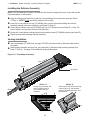
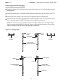
Preparing Points for Hanging
1 Transfer the heater’s three hanging locations to the ceiling where the unit is to be installed and mark
hanging points.
2 Prepare mounting surface. If necessary attach additional support blocks and drill holes (Figure 3.5).
3
Fasten beam clamp, screw hook or other type of suspension anchor to hanging point.
4 Attach and close S-hook (P/N: S-HOOK) and #1 double-loop chain (P/N: AV-CS) to anchor. Check
that it is securely attached. NOTE: Threaded rod and turnbuckles may be used.
NOTE: The unit must be in straight alignment and level. Adjust chain lengths until radiant tubing is
level and equal weight distribution is achieved. Chains must be straight up and down. Do not install
chains at an angle as this can result in tube warpage or separation.
Figure 3.5 • Hanging Types
Concrete
Beam
Wood
Beam
Screw Hook
Support
Blocking
Support
Blocking
S-Hook and #1
Double-Loop Chain
Beam Clamp
Beam Clamp
I-Beam
I-Beam
Threaded Rod and
Turnbuckle
S-Hook and #1
Double-Loop Chain
Turnbuckle
15
3.0 Installation • Hanging Pre-Assembled Unit
AVS Series
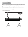
Hanging Pre-Assembled Unit
1
Raise the assembled unit from assembly station to prepared hanging location. NOTE: This can be
done manually or with a winch system.
2
Attach two chains to exchanger connection hanging bracket (TP-6079). Secure S-hooks.
3
Attach the third chain located furthest from the gas and electrical connections to the reflector end
assembly (TP-6089A) and secure S-hook.
4
Raise or lower the unit to desired mounting height.
Figure 3.6 • Hanging the Heater
16
3.0 Installation • Hanging Pre-Assembled Unit • Final Check List
AVS Series
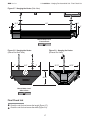
Figure 3.7 • Hanging the Heater (Side View)
13.5”
83”
4.5”
2”
3”
Mount Heater Level
- Front to Back -
Figure 3.8 • Hanging the Heater
(Burner Box Back View)
7”
11.5”
Figure 3.9 • Hanging the Heater
(Exhaust End View)
7”
12.75”
12.25”
Mount Heater Level
- Side to Side -
Final Check List
1
2
Check the unit for level across the length (Figure 3.7).
Check the unit for level across the width (Figure 3.8).
17
12.75”
3.0 Installation • Venting
AVS Series
Venting
!
WARNING
Insufficient ventilation and/or improperly sealed vents may release gas into the building
which could result in health problems, carbon monoxide poisoning or death.
Improper venting may result in fire, explosion, injury or death.
Seal vent pipes with high temperature sealant and three (3) #8 sheet metal screws.
Vent enclosed spaces and buildings according to the guidelines in this manual and
applicable national, state, provincial and local codes.
This tube heater must be vented in accordance with the requirements within this manual and all applicable
codes for all models, prior to operating unit. Local codes may vary.
In the absence of local codes:
United States: Refer to NFPA 54/ANSI Z223.1 (latest edition), National Fuel Gas Code.
Canada: Refer to CAN/CGA B149.1 Installation Code for Gas Burning Appliances.
The heating system may operate either vented or unvented. Venting can terminate through the sidewall
(horizontal) or the roof (vertical) and be individually or commonly vented.
Venting Requirements
• 4 in. single wall 26 gauge (min.) galvanized steel vent pipe or Dura/Connect single wall flexible
exhaust vent must be used.
• Maximum vent length for all models is 30 ft. (9 m).
• Single wall galvanized vent pipe must be insulated in cold environments.
• Seal single wall vent with high temperature sealant (field supplied)and three (3) #8 sheet metal
screws (field supplied).
• Do not use more than two (2) 90° elbows in the exhaust vent.
• To maintain clearances to combustibles, the use of an approved wall or roof thimble and doublewall Type B-vent is required for the portion of vent pipe that runs through combustible material in
the building wall or roof (see Figures 3.11 - 3.14).
• Consult the NFPA ANSI Z223.1 Gas Vent Termination criteria if roof pitch exceeds 9:12.
18
3.0 Installation • Venting • Unvented Operation
AVS Series
Unvented Operation
!
WARNING
Not for residential use. The use of unvented tube heaters in residential indoor spaces
may result in property damage, serious injury or death. Use unvented operation in
commercial and industrial installations with proper ventilation rates only.
When using an unvented configuration (agricultural use only), consider the following:
• A factory supplied vent cap/diffuser (P/N: WVE-GALV) must be used.
• Where unvented heaters are used, natural or mechanical means must be provided to supply
adequate ventilation - a minimum of 4 cfm/1000 BTU/h (0.38 m3 /kW) input of installed heaters.
NOTE: Gravity or mechanical means may be used to accomplish the air displacement. Local
codes may require that the mechanical exhaust system be interlocked with the electrical supply
line to the heaters, enabling both to function simultaneously.
• Exhaust openings for removing the flue products must be located above the level of the
heater(s).
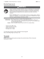
Figure 3.10 • Minimum Clearances
6 in.
Min.
to Back
12 in.
Min.
to End
19
3.0 Installation • Venting • Sidewall Venting
AVS Series
Sidewall Venting
Guidelines:
Vent Pipe Angle
• To prevent moisture from entering the heater system, slope the vent pipe downward toward the
outlet 1/4 in. per foot of length. Do not pitch the heater.
• **Vent must extend beyond any combustible overhang if the vent is less than 36 in. below the
combustible overhang.
Figure 3.11 • Sidewall Venting Requirements
Building Overhang**
Sidewall
6 in.
min.**
Heater
B to C Adapter
36 in.
min.**
Sidewall Vent Cap
Single
Wall Vent
Double-Wall
B-Vent
Wall Thimble
1/4 in. downward
pitch per foot
Vent Termination
United States:
• Vent must terminate a minimum of 4 ft. (1.2 m) below, 4 ft. (1.2 m) horizontally from, and 1 ft.
(30 cm) above any window or door that may be opened or gravity air inlet into the building.
• Vent must terminate a minimum of 3 ft. (.9 m) above any forced air inlet that is located within
10 ft. (3.1 m).
• The bottom of the vent terminal must be located a minimum of 12 in. (30 cm) above grade level
and must extend beyond any combustible overhang. Vents adjacent to public walkways must
terminate a minimum of 7 ft. (2.1 m) above grade level.
• The vent terminal must be installed to prevent blockage by snow and protect building materials
from degradation by flue gases.
• The vent cap must be a minimum of 6 in. (15.2 cm) from the sidewall of the building.
• Vent must be a minimum of 36 in. below or extend beyond any combustible overhang.
Canada:
• Vents must terminate a minimum of 3 ft. (.9 m) from a window or door that may be opened, and
non-mechanical air supply inlet or combustion air inlet into the building.
• Vents must terminate a minimum of 6 ft. (1.8 m) from a mechanical air supply inlet.
20
3.0 Installation • Venting • Rooftop Venting
AVS Series
Rooftop Venting
Guidelines:
Vent Locations and Clearances
• Separate air intake duct from vent pipe a minimum of 4 ft. (1.2 m) by placing vent pipes higher
than adjacent air intake duct.
• Venting may utilize standard B-vent cap.
• The vent terminal must extend a minimum of 2 ft. (.6 m) above the roof.
Figure 3.12 • Rooftop Venting - Side View
Vent Cap
24 in. Min.*
Roof*
Storm Collar
Adjustable Roof Flashing
1 in. Minimum Clearance
1 in. Minimum Clearance
Double-Wall B Vent Pipe
Firestop Spacer
B to C Adapter
Heater
Single-Wall Elbow or
Alternate Tee Fitting
Single-Wall Vent
(field supplied)
#8 Sheet Metal Screws
(field supplied)
*Consult the NFPA ANSI Z223.1 Gas Vent Termination criteria if roof pitch exceeds 9:12.
21
3.0 Installation • Venting • Common Venting
AVS Series
Common Venting
• When joining two heaters to a common vent, a staggered arrangement or a dual exhaust assembly
(P/N: YSM) must be used so that by-products of one heater do not flow into the adjoining vent of the
other heater.
• 6 in. diameter double-wall Type B-vent and 6 in. vent cap must be used.
• Common vented heaters must be controlled with the same thermostat. Do not operate individually.
Figure 3.13 • Common Rooftop Venting - Side View
Rooftop Vent Cap
*Consult the NFPA ANSI Z223.1 Gas Vent
Termination criteria if roof pitch exceeds 9:12.
24 in.
Min.*
Roof
Double-Wall B
Vent
Firestop Spacer
Heater
Heater
Dual Exhaust
Assembly
Figure 3.14 • Common Sidewall Venting - Top View
Sidewall
6 in.
Min.
Heater
B to C
Adapter
Sidewall Vent Cap
Dual Exhaust
Assembly
Wall Thimble
Double-Wall B-Vent
Heater
Single Wall Vent
22
3.0 Installation • Combustion Air Requirements
AVS Series
Combustion Air Requirements
Combustion air may be supplied to the heater by indoor or outdoor means.
If using combustion air intake from indoors, the required volume of the space must be a minimum of 50 ft3
per 1000 BTU/hr (4.8 m3 /kW) unless the building is of unusually tight construction. If the building is of
unusually tight construction with air infiltration rates of less than 0.40 air changes per hour, outside
combustion air is typically needed unless the sheer size of the building allows otherwise. Contact the
factory for further determination of air infiltration rates.
Non-contaminated outside air for combustion must be ducted to the heater if any of the following apply:
• Chemicals such as chlorinated or fluorinated hydrocarbons (typical sources are refrigerants, solvents,
adhesives, degreasers, paints, paint removers, lubricants, pesticides, etc.).
• High humidity.
• Contaminants such as sawdust, welding smoke, etc.
• Negative building pressure.
• Unusually tight construction where there is an air infiltration rate of less the 0.40 air changes per hour.
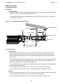
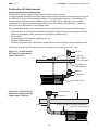
Combustion air intake may be located on either the sidewall or roof (see figures 3.15 - 3.18).
Figure 3.15 • Vertical Outside
Air Supply for Single Heater
Intake • Side View
Inlet Cap
4” Inlet Duct
Tri-Ply
Truss
Drill 4-3/4” ø
hole into header.
2”x6”x12” Header
Wood Screw x2
Field Supplied)
Adapter
Flexible Boot
Burner
Box
Figure 3.16 • Optional Vertical
Outside Air Supply for Single
Heater Intake • Side View
Worm Gear Clamp
Roof Intake Cap
Roof
18 in. Minimum
Air Inlet Connection (Flexible boot and band
clamps are recommended)
4” pipe
Burner
Box
23
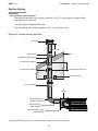
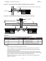
3.0 Installation • Combustion Air Requirements
AVS Series
Figure 3.17 • Horizontal Outside Air Supply for Single Heater Intake • Side View
Air Inlet Connection (Flexible boot and band clamps are recommended)
Wall
Air Intake Cap
4” pipe
Burner
Box
Figure 3.18 • Vertical Outside Air Supply for Common Heater Intake • Side View
Roof Intake Cap
NOTE: Common intake heaters
must share the same thermostat.
18 in.
Minimum
Air Inlet Connection
Burner
Box
4” intake pipe
Roof
6” pipe
Air Inlet Connection (Flexible boot and band
clamps are recommended)
4” intake pipe
Burner
Box
Guidelines:
Chart 3.4 • Limitations for Length and Size of Combustion Air Intake Duct
Single Heater Intake
Dual Heater Intake
Air Intake Duct Size
Max. Intake Length
Duct Size
Max. Intake Length
4 in.
20 ft.
4 in.(single)/6 in.(dual)
20 ft.
5 in.
30 ft.
4 in.(single)/8 in.(dual)
30 ft
6 in.
40 ft.
Consult factory for longer intake lengths.
General
• No more than two (2) 90° degree elbows are allowed.
• Allow for expansion. Use a 4 in. flexible hose to connect the duct to the burner control box.
• In humid environments, use insulated duct, PVC pipe or DWV (drain waste vent) to prevent
condensation on the outer surface.
• A factory approved wall intake cap (P/N: WIV-4) must be used with horizontal outside intake
ducts. The wall intake cap (P/N: WIV-4) must be installed to prevent blockage. Locate the intake
where dirt, steam, snow, etc. will not contaminate or clog the intake screen.
• Separate air intake duct from vent pipe a minimum of 4 ft. Also, place vent pipe higher than
adjacent air intake duct.
24
3.0 Installation • Gas Supply
AVS Series
Gas Supply
!
WARNING
Improperly connected gas lines may result in fire, explosion,
poisonous fumes, toxic gases, asphyxiation or death. Connect
gas lines in accordance to national, state, provincial and local
codes.
IMPORTANT! Before connecting the gas supply to the burner control box:
• Verify that the heater’s gas type (as listed on the rating plate) matches that of your application.
• Check that the gas piping and service has the capacity to handle the total gas consumption of all
heaters being installed, as well as any other gas appliances being connected to the supply line.
• Check that the main gas supply line is of proper diameter to supply the required fuel pressures.
• If utilizing used pipe, verify that its condition is clean and comparable to a new pipe. Test all gas
supply lines in accordance with local codes.
• Test and confirm that inlet pressures are correct. Refer to the heater rating plate for gas type and
the required minimum and maximum pressures (see Chart 3.5). The gas supply pipe must be of
sufficient size to provide the required capacity and inlet pressure to the heater (if necessary,
consult the local gas company). Do not exceed the maximum allowed pressures for the heater,
the space or the gas piping system.
Chart 3.5 • Manifold Pressure
Type of
Gas
Required Manifold
Pressure
Minimum Inlet
Pressure
Maximum Inlet
Pressure
Natural
3.5 Inches W.C.
5.0 Inches W.C.
14.0 Inches W.C.
Liquefied Propane
10.0 Inches W.C.
11.0 Inches W.C.
14.0 Inches W.C.
NOTE: Check manifold pressure at the tap on the gas valve. Small variations in manifold pressure
(actual vs. published) may exist due to changing atmospheric conditions. Readings will be above
atmospheric pressure.
Pressure Equivalents: 1 Inch W.C. equals .058 oz/sq. in. equals 2.49 mbar.
NOTE: When installing in areas with high altitude please refer to these chats with orifice eqivalents
Natural Gas @ 3.5 inches W.C
BTU/h
Standard
Orifice
5,000 ft.
6,000 ft.
7,000 ft.
8,000 ft.
40,000
44
46
47
47
47
60,000
37
39
41
41
41
80,000
31
32
32
32
33
Propne Gas @ 3.5 inches W.C
BTU/h
Standard
Orifice
5,000 ft.
6,000 ft.
7,000 ft.
8,000 ft.
40,000
55
55
55
55
56
60,000
52
52
53
53
53
80,000
49
50
50
50
51
For altitudes above 8,000 ft, consult factory.
25
3.0 Installation • Gas Supply
AVS Series
To connect the gas:
WARNING
!
Failure to install, operate or service this appliance in the approved manner may result in
property damage, injury or death. Only trained, qualified gas installation and service
personnel may install or service this equipment.
The installation must conform with local building codes or, in the absence of such codes, the National Fuel
Code (NFPA 54) and in conjunction with ANSI Z21.24/CSA 6.10 “Connectors for Gas Appliances”.
IMPORTANT! The heating system will expand and contract during operation. Allowances for expansion
must be made between the connection to the heater and the gas supply. Excessive bending, kinks,
twists or vibration must be avoided. A flexible gas connection of approved type is required. Flexible Type 1
rubber gas connectors, or other approved connection device, installed in one plane, and without sharp
bends, kinks or twists is recommended.
The gas pipe and connection must be supported independently. Do not install gas supply line in a
manner that bears the weight of the heater. Connect the main gas supply line with an approved flexible
connector (Figure 3.19) or, if national or local codes require rigid piping, a swing joint. Heater shall not
be connected to the building piping system with rigid pipe or semi-rigid metallic tubing, including
copper. When using such material, an intermediate connection device that allows for heater expansion
must be used.
The gas outlet must be in the same room as the appliance and accessible. It may not be concealed
within or run through any wall, floor or partition. When installing the heater in a corrosive environment
(or near corrosive substances), use a gas connector suitable for the environment. Do not use the gas
piping system to electrically ground the heater.
1
Install a sediment trap / drip leg if condensation may occur at any point of the gas supply line. This
will decrease the possibility of loose scale or dirt in the supply line entering the heater’s control
system and causing a malfunction. NOTE: High pressure gas above 14 Inches W.C. (water column
pressure) requires a high pressure regulator and ball valve.
2
Form the approved flexible connector (field supplied) into a U-shape allowing a maximum of 14 in.
between the flexible connector’s end nuts (see Figures 3.19-3.20).
3 Attach the ball valve (optinal) to the gas supply pipe. Apply pipe compound to NPT adapter
threads to seal the joint. Use only a pipe compound resistant to LP.
NOTE: Provide a 1/8 in. NPT plugged tapping accessible for test gauge connection immediately
upstream of gas connection to the heater.
!
CAUTION
When using a Type 1 rubber flexible gas connector, do not attach the connector nuts directly to the gas
pipe supply. Connector nuts must be installed to an approved adapter.
26
3.0 Installation • Gas Supply
AVS Series
4
Attach the flexible connector to the adapter and burner control box inlet. Seal the joints.
NOTE: Excessive torque on the manifold may misalign the orifices. Always use two wrenches to
tighten mating pipe connections. Final assembly must be tested for gas leaks according to NFPA 54
and all local codes and/or Standards.
!
WARNING
Testing for gas leaks with an open flame or other sources of ignition may lead to a
fire or explosion and cause serious injury or death. Test in accordance with NFPA
or local codes.
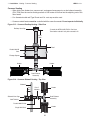
Figure 3.19 • Gas Connection (Approved Flexible Gas Connection) • Control Box Side View
Ball Valve / Inlet Tap
Burner
Control Box
Side View
Heater Movement/Expansion
Type 1 Hose Gas Connector, formed into a U-bend
Figure 3.20 • Gas Connection (Approved Flexible Gas Connection) • Control Box Back View
Burner Control Box
End View
Ball Valve / Inlet Tap
Adapter
Adapter
Elbow
Elbow
Drip Leg/
Sediment Trap
ŒŒ
Type 1 Hose Gas Connector, formed into a U-bend
27
3.0 Installation • Electrical Requirements • Thermostat
AVS Series
Electrical Requirements
!
WARNING
Improper installation, adjustment, alteration, service or maintenance can cause property
damage, serious injury or death. Read and understand, the installation, operating and
maintenance instructions thoroughly before installing or servicing this equipment. Only
trained, qualified gas installation and service personnel may install or service this
equipment.
Not for residential use! Do not use this heater in the home, sleeping quarters, attached
garages, etc. Installation of a commercial tube heater system in residential indoor spaces
may result in property damage, serious injury or death.
The heater must be electrically grounded in accordance with the following codes:
United States: Refer to National Electrical Code®, ANSI/NFPA 70 (latest edition). Wiring must
conform to the latest edition of the National Electrical Code®, local ordinances, and
any special diagrams furnished.
Canada: Refer to Canadian Electrical Code CSA C22.1 Part 1 (latest edition).
•
•
•
•
120 Volt - 60 Hz GRD, 3-wire.
120VAC thermostat connection.
Starting current 1.5 amps.
Running current 1.1 amps.
The 120V supply connection is factory wired with a three-prong pig tail.
Refer to Field Wiring Diagram (see Figure 3.22).
Thermostat
NOTE: Different thermostats operate according to their particular features. Refer to thermostat
specifications for details.
28
3.0 Installation • Electrical Requirements • Field Wiring
AVS Series
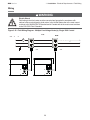
Wiring
!
WARNING
Electric Shock
Field wiring to the tube heater must be connected and grounded in accordance with
national, state, provincial and/or local codes. In the United States refer to the most current
revisions to the ANSI/NFPA 70 Standard and in Canada refer to the most current revisions
to the CSA C22.1 Part I Standard.
Figure 3.22 • Field Wiring Diagram • Multiple Line Voltage Heater(s), Single 120V Control
must
0VA - 0
NOTE:
S
T
A
0VA
0VA
29
3.0 Installation • Electrical Requirements • Internal Wiring Diagrams
AVS Series
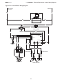
Before field wiring this appliance - Check existing wiring; replace if necessary.
NOTE: If any of the original wire supplied with the appliance must be replaced, it must be replaced with
wiring material having a temperature rating of at least 105° C.
Figure 3.23 • Internal Ladder Wiring Diagram
?$F>
ZXF
{X
?$!F
@
@!
^$!
@
@
@
@
ZX`[
$!F?+!^!
!++!
+$
@
@
Z
?
|[?}
+Z
+
;F>?+$
>$
|[?}!
@
@
>
!
>?;
>?;
!
?;
F$!>$
F^+?+!
F^+?+!
+?>\+$F>
>F+F
+F!>?$!+
30
>
3.0 Installation • Electrical Requirements • Internal Wiring Diagrams
AVS Series
Figure 3.24 • Internal Block Wiring Diagram
?$F>
ZXF
{X
?$!F
@
@
@
@
@
ZX`[
$!F?+!^!
@
!++!
+$
@
@
Z
?
|[?}
+Z
+
@
;F>?+$
>$
|[?}!
>
!
?;
F$!
>$
>?;
>?;
!
F^+?+!
+?>\+$F>
>F+F
F^+?+!
+F!>?$!+
31
>
4.0 Operation • Operating Instructions • Lighting Procedures • Shutdown Procedures
AVS Series
4.0 Operation
!
WARNING
This appliance does not have a pilot ignition. It is equipped with an ignition device
which automatically lights the burner. Do not attempt to light the system by hand.
BEFORE OPERATING, smell all around the appliance area for gas. Be sure to smell next to the floor
because some gas is heavier than air and will settle to the floor. Refer to the cover page “If you smell gas”
and on the safety label affixed to the heater.
Do not use this appliance if any part has been under water. Immediately contact a qualified service
technician to inspect the appliance and to replace any part of the control system and any gas control
which has been under water.
Start-up and Shutdown Procedures
!
WARNING
Use only your hand to turn the manual shutoff. Never use tools. If the
knob will not turn by hand, don’t try to repair it; call a qualified technician.
Force or attempted repair may result in a fire or explosion.
Start-up Procedures:
1
2
3
4
5
6
7
8
9
STOP! Read the safety information above.
Set the thermostat to the lowest setting.
Turn OFF all electrical power to the appliance.
Turn manual shutoff clockwise
to “OFF”.
Wait five (5) minutes to clear out any gas. If you smell gas STOP! Follow the safety information
found on the cover page under “If you smell gas” and on safety label affixed to the heater. If you do
not smell gas, proceed to step 6.
Turn manual shutoff knob counterclockwise
to “ON”.
Turn ON all electrical power to the appliance.
Set thermostat to desired setting.
If the appliance will not operate, follow instructions below to turn OFF gas to the appliance and call
your service technician or gas supplier.
Shutdown Procedures:
1
2
3
Set the thermostat to the lowest setting.
Turn OFF all electrical power to the appliance if service is to be performed.
Turn manual shutoff knob clockwise
to “OFF”. Do not force.
32
4.0 Operation • Sequence of Operation
AVS Series
!
WARNING
This heater must be installed and serviced by trained gas installation and service
personnel only.
Do not bypass any safety features or the heater’s built in safety mechanisms will
be compromised.
Sequence of Operation
Starting Circuit: Upon a call for heat, the fan and transformer is energized by 120VAC from the
thermostat/controller. Once operational static pressure is achieved, the differential pressure switch
closes, sending power to the ignition module. After a seven-second pre-purge, the spark igniters
and the solenoid of the gas valve are simultaneously energized. The trial for ignition is 15 seconds.
Running Circuit: After ignition, the control monitors burner flame through the flame sensors. If sense of
flame is lost, the control immediately sparks (identical to the starting sequence). If flame sense is not
established within 15 seconds, the heater will attempt two (2) additional ignition sequences before
proceeding to lockout mode. The control can be reset by briefly interrupting the power source.
33
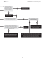
5.0 Maintenance • Troubleshooting Guide
AVS Series
5.0 Maintenance
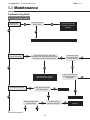
Troubleshooting Guide
Turn up thermostat/controller.
Does the fan
blower turn on?
Is the power at the
heater 120V?
No
Yes
The blower assembly
is faulty and must be
replaced.
Yes
No
Find the source of the electrical problem between panel and heater.
Is there 24V at the blue and yellow
secondary side of the internal transformer
and common on the pressure switch?
No
Does the unit spark?
Is there 24V at the
N.O. terminal of the
pressure switch?
Yes
No
No
Yes
Check wire connection to primary
of the transformer. If good,
replace faulty transformer.
Do both burners light?
No
Is the ball valve/shut-off
in the ON position?
No
Is the inlet or the outlet
of the unit plugged or
obstructed?
Does the amber valve
light illuminate?
No
Are the igniter(s)
physically damaged?
No
Yes
Continued on page 36
34
No
Turn On.
Yes
Yes
Yes
Yes
Remove obstruction.
Yes
Replace damaged
igniter(s).
5.0 Maintenance • Troubleshooting Guide
AVS Series
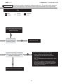
*
NOTICE
Bypassing any switch is intended for testing purposes only. Do not leave switch bypassed
during normal operation or the heater’s built-in safety mechanisms will be compromised.
Key
Start
Question
Process
Question
Corrective
Action
Check both high temperature spark
wires and both electrodes. If good,
replace circuit board.
Yes
Is there 24V across
the circuit board with
terminal to ground?
No
Check for loose wiring or restrictions
in the hose connections to pressure
switches. Are they OK?
Repair faulty wiring.
Replace the pressure switch after verifying:
Yes
• Heater, fan blowers ,squirrel cage, intake
and exhaust are clean and free from dirt and
obstructions.
• The 4” air intake pipe does not exceed 30 ft. and/or
2 elbows.
• There is not a negative pressure experienced at
the area of air intake (e.g.; high winds, attic space,
tightly sealed building). May vary for agricultural
buildings (consult factory).
No
Replace wiring or hose connections.
35
5.0 Maintenance • Troubleshooting Guide
AVS Series
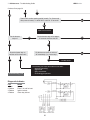
Continued from page 34.
No
Yes
Yes
Test for 24V at valve opening period (usually 7 to 10 seconds
after power to heater). Is there 24V to valve for 15 seconds?
Yes
No
Replace circuit board.
Do the burners
stay on?
Do the burners stay on for approx.
15 seconds and then shut off?
No
No
Yes
Do the burners come on and turn
off immediately (1 to 2 seconds)?
Does the heater stay on
until the call for heat ends?
Yes
No
No
Troubleshooting ends.
Yes
Contact factory.
The following can cause the heater to shut down:
• Improper grounding.
• High winds.
• Dirty environment.
• Fluctuating gas pressure.
Diagnostic Indicator
LED
1 Flash
2 Flashes
3 Flashes
4 Flashes
Yes
MODE
Start up.
Flame. No call for heat.
Ignition lockout.
Valve relay lockout.
36
5.0 Maintenance • Troubleshooting Guide
AVS Series
Check to make sure
gas pressure is within
minimum and maximum
inputs, as indicated
Replace gas valve.
Yes
No
Correct problem.
No
Is the heater properly grounded?
Is the heater’s polarity correct?
Yes
With microampmeter, check
DC ampperage at flame rods.
Is it 1.0 microamps?
No
Check to make sure gas pressure is
within minimum and maximum inputs as
indicated on the heater’s rating plate.
Is gas pressure OK?
Correct
problem.
No
Yes
Check to make sure both flame
sensor wires are OK and then
replace circuit board.
Yes
Pressure switch may be faulty or there
is a restriction in the exhaust. Remove
restriction or replace pressure switch.
One or both of the flame sensing rods are faulty or flame is
weak. Check to make sure heater is operating at proper gas
pressure as indicated on the heater’s rating plate.
If needed, replace one or both flame sensing rods.
37
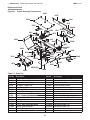
5.0 Maintenance • Heater Components and Parts List
AVS Series
Replacement Parts
Figure 5.1 • Burner Assembly Components
6005
6007
3014
3022
6013
6070
6225
6065 1528
826
6069
6070
6015
6011
222 3055
6009
204
6003
6011
6044
6053
6051
6001
3055
6004
222
6053
6012
6056
337
6012
6055
6056
6055
13,62
6021A
6019
6040,6041
6023
204
6002A
6008A
264G
6024
6047
6048
68B
933
6074
6076
6027
828
6020A,B,C
6022
6006
Chart 5.1 • Parts List
Part No.
Description
Part No.
Description
TP-13
TP-62
TP-68B
TP-204
TP-222
TP-264G
TP-337
TP-826
TP-828
TP-933
TP-1528
TP-3014
TP-3022
TP-3055
TP-6001
TP-6002A
#8 x 1/2” Self-Drilling Screw
#8 x 1/2” Aluminized Sheet Metal Screw
Large Strain Relief Bushing
Gas Orifice - Specify Size
Flame Sensing Rod
Air Proving Switch
Electrical Plastic Bushing
40VA Transformer - 120V Pri./124V Sec.
24VAC Indicator Light
6’ Black 120VAC Power Cord
Post Purge Timer
Combustion Air Inlet Collar w/ Screen
#8 x 1/2” Black Sheet Metal Screw
2 Prong Ignition Electrode
Control Mounting Panel
Burner Box Left Side Panel
TP-6003
TP-6004
TP-6005
TP-6006
TP-6007
TP-6008A
TP-6009
TP-6011
TP-6012
TP-6013
TP-6015
TP-6019
TP-6020A
TP-6020B
TP-6020C
TP-6021A
Burner Box Right Side Panel
Burner Box Front Panel w/9 Weld Studs
Burner Box Top Cover
Burner Box Bottom Panel
Burner Box Rear Panel, Upper
Burner Box Rear Panel, Lower
Burner Center Panel
Burner Mounting Holster
Burner and Ignition Supporting Frame
Service Access Handle
Fan Motor Assembly
Exhauster Collector Box
Fan Restrictor Plate - 40
Fan Restrictor Plate - 60
Fan Restrictor Plate - 80
Fan Gasket
38
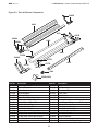
5.0 Maintenance • Heater Components and Parts List
AVS Series
Figure 5.2 • Tube & Reflector Components
6085A
6088
6079
6021B
6084A
6082
6086A
6084A
6077B
6082
6089A
6087A
6077B
6075
6077A
6077A
6087A
6080
WVE-GALV
Part No.
Description
Part No.
TP-6021B
TP-6022
TP-6023
TP-6024
TP-6027
TP-6040
TP-6041
TP-6044
TP-6047
TP-6048
TP-6051
TP-6053
TP-6055
TP-6056
TP-6065
TP-6069
Tube Flange Gasket
5/16” - 18 Keps Nut
Rubber Grommet
Gas Inlet Adapter
1/2” Plastic Plug
Natural Gas Valve; Single-Stage
LP Gas Valve; Single-Stage
Manifold Pipe w/ Foot Mounts
5” x 1/2” Gas Inlet Pipe
1/2” Gas Inlet Street Elbow
Dual DSI Circuit Board
Igniter and Sense Mounting Plate
26” High Temp. Spark Wire w/Boot (Orange)
26” High Temp. Sense Wire (Purple)
12” x 5/32” I.D. Silicone Pressure Tubing
Port Barb Fitting
TP-6070
TP-6074
TP-6075
TP-6076
TP-6077A
TP-6077B
TP-6079
TP-6080
TP-6082
TP-6084A
TP-6085A
TP-6086A
TP-6087A
TP-6088
TP-6089A
WVE-GALV
39
Description
Burner
Sight Glass Plug
81” x 4” Vent Pipe
4” Vent Collar
U-Bolt Fastener
3/8”-16 Keps Nut
Exchanger Connection and Hanging Bracket
4” Vent Adapter Fitting
Radiant U-Tube Assembly w/ Baffle and Plate
U-End Reflector End Cap
Burner Reflector End Cap
#8 x 1/2” Red Shoulder Screw
Tube Saddle Bracket
Aluminum Reflector
Refl. End Assembly w/Saddle Brackets
4” Galvanized Vent Flapper Cap
5.0 Maintenance • Routine Inspection
AVS Series
!
WARNING
Personal injury or death may result if maintenance is not
performed by properly trained gas installer or service
personnel. Contact the installing distributor or place of
purchase for service. Do not operate heating system if
repairs are necessary.
Allow heater to cool prior to servicing.
Disconnect power to heater before servicing.
Use protective glasses when maintaining the heater.
Routine Inspection
At least once per year, the heating system should be inspected and serviced by trained gas installation
and service personnel only. This inspection should be performed at the beginning of the heating
season to insure that all heater components are in proper working order and that the heating system
operates at peak performance. Particular attention should be paid to the following items.
•
Blower Motor: Ensure that the squirrel cage in the blower is kept clean. If dirt becomes a problem,
installation of outside air intake ducts for combustion is recommended.
•
Vent pipe system: Check the outside termination and the connections at the heater. Inspect the vent
exhausts for leakage, damage, fatigue, corrosion and obstructions. If dirt becomes a problem,
installation of outside air intake ducts for combustion is recommended.
•
Combustion air intake system (when applicable): Check for blockage and/or leakage. Check the
outside termination and the connection at the heater.
•
Heat exchangers: Check the integrity of the heat exchangers. Replace if there are signs of structural
failure. Check for corrosion and/or buildup within the tube exchanger passageways. Check level both
ways (side to side; front to back).
•
Burner: Check for proper ignition, burner flame and flame sense. Flame should extend directly
outward from burner without floating or lifting.
•
Wiring: Check electrical connections for tightness and/or corrosion. Check wires for damage.
•
Gas Connection: Inspect the integrity of the gas connection to the heater. Check for leaks, damage,
fatigue or corrosion. Do not operate if repairs are necessary and turn off gas supply to the heater.
Contact service personnel.
•
Reflectors: Inspect the integrity of the reflectors for damage, separation, missing or misaligned
sections and that reflector rotation does not exceed 45° from horizontal. Do not operate if repairs are
necessary. Repair or replace as required per the general installation manual.
To maintain effective infrared heating, always keep both sides of the reflector clean. Dirt and dust can
be vacuumed or wiped clean with a soap and water solution. Use metal polish if the reflectors are
severely dirty.
Contact service personnel if repairs are necessary. Do not operate unit.
40
5.0 Maintenance • Maintenance Log Inspection
AVS Series
Maintenance Log
Date
Maintenance Performed
41
Replacement Parts Required
AVS Series
Notes
42
AVS Series
5.0 Maintenance • Limited Warranty Terms and Conditions
Limited Warranty Terms and Conditions
One-Year Limited Warranty. Radiant Tube Heaters covered in this manual, are warranted by Brant Radiant
Heaters Limited to the original user against defects in workmanship or materials under normal use for one year after
date of purchase. Any part which is determined to be defective in material or workmanship and returned to an
authorized service location, as Brant Radiant Heaters Limited designates, shipping costs prepaid, will be, as the
exclusive remedy, repaired or replaced at Brant Radiant Heaters Limited’s option. For limited warranty claim
procedures, see PROMPT DISPOSITION below. This limited warranty gives purchasers specific legal rights which
vary from jurisdiction to jurisdiction.
Additional Limited Warranty. In addition to the above mentioned one-year warranty, Brant Radiant Heaters
Limited warrants the original purchaser an additional extension on the radiant tubes and combustion burner. This
extension excludes electrical/purchased components.
General Conditions. The Company will not be responsible for labor charges for the analysis of a defective
condition of the heater or for the installation of replacement parts. The warranties provided herein will not apply if the
input of the heater exceeds the rated input at time of manufacturing or if the heater in the judgment of the Company
has been subjected to misuse, excessive dust, improper conversion, negligence, accident, corrosive atmospheres,
excessive thermal shock, excessive vibration, physical damage to the heater, alterations by unauthorized service
personnel, operation contrary to the Company’s instructions or if the serial number has been altered, defaced, or
removed. The Company shall not be liable for any default or delay in the performance of these warranties caused
by contingency beyond its control, including war, government restriction or restraints, strikes, fire, flood, short or
reduced supply of raw materials, or parts.
Limitation of Liability. To the extent allowable under applicable law, Brant Radiant Heaters Limited’s liability for
consequential and incidental damages is expressly disclaimed. Brant Radiant Heaters Limited’s liability in all events
is limited to and shall not exceed the purchase price paid.
Warranty Disclaimer. Brant Radiant Heaters Limited has made a diligent effort to provide product information and
illustrate the products in this literature accurately; however, such information and illustrations are for the sole
purpose of identification, and do not express or imply a warranty that the products are merchantable, or fit for a
particular purpose, or that the products will necessarily conform to the illustrations or descriptions. Except as
provided below, no warranty or affirmation of fact, expressed or implied, other than as stated in the “LIMITED
WARRANTY” above is made or authorized by Brant Radiant Heaters Limited.
Product Suitability. Many jurisdictions have codes and regulations governing sales, construction, installation, and/
or use of products for certain purposes, which may vary from those in neighbouring areas. While Brant Radiant
Heaters Limited attempts to assure that its products comply with as many codes, it cannot guarantee compliance,
and cannot be responsible for how the product is installed or used. Before purchase and use of a product, review
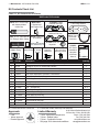
the product applications, and all applicable national and local codes and regulations, and be sure that the product,
installation, and use will comply with them. Certain aspects of disclaimers are not applicable to consumer products:
e.g., (a) some jurisdictions do not allow the exclusion or limitation of incidental or consequential damages, so the
above limitation or exclusion may not apply to you: (b) also, some jurisdictions do not allow a limitation on how long
an implied warranty lasts, consequently the above limitation may not apply to you: and (c) by law, during the period
of this limited warranty, any implied warranties of implied merchantability or fitness for a particular purpose
applicable to consumer products purchased by consumers, may not be excluded or otherwise disclaimed.
Prompt Disposition. Brant Radiant Heaters Limited will make a good faith effort for prompt correction or other
adjustment with respect to any product which proves to be defective within limited warranty. For any product
believed to be defective within limited warranty, first write or call dealer from whom the product was purchased.
Dealer will give additional directions. If unable to resolve satisfactorily, write to Brant Radiant Heaters Limited at
address indicated on page 44, giving dealer’s name, address, date and number of dealer’s invoice, and describe the
nature of the defect. Title and risk of loss pass to buyer on delivery to common carrier. If product was damaged in
transit to you, file claim with carrier.
43
5.0 Maintenance • Kit Contents Check List
AVS Series
Kit Contents Check List
Chart 5.2 • Kit Contents for AVS Series
AVS Series Kit Contents
Packed with Emitter Assembly and Reflectors
AK-IP: 29” x 4” PVC Pipe
with Attached Metal
Intake Cap
WVE-GALV:
4” Galvanized
Vent Flapper Cap
TP-6089A: U-End
Reflector End Cap
Packed with Burner Control Box
TP-6021B:
Tube Flange Gasket
TP-6085A: Burner
Reflector End Cap
RH1/2: Type 1
Hose Gas
Connector
AIRH: 18” x 4” Inlet Hose w/ AV-CS: Chain Set
w/ S-Hooks
PVC Fitting & Worm Clamp
TP-6022: 5/16”-18
Keps Nut
TP-6080: 4” Vent TP-13: SelfAdapter Fitting Drilling Screw
TP-6086A:
AK-WS: TP-62: #8 x 1/2”
#8 x 1/2” Red
Screw for
2” Wood
Shoulder Screw
Reflectors
Screw
Brant Radiant Heaters, Ltd.
LIOAVS:
AVS Series
Installation,
Operation
and Parts
Manual
AVS Series
Gas-Fired Infrared
ad T be Heater
,
,
,
,
!
Not for residentia
WARNING
se
NOT
,
,
,
,
,
,
,
Interdit o r sa e r sidentie .
,
,
,
NOT
,
,
,
,
S
A
For Yo r Safety
If yo s e
Consi nes De S
as:
rit
Si o s sentez ne ode r de az:
ee t ese instr
tions for f t re referen e.
AVS 0
Box
Part No.
Description
Quantity
T
AIRH
18” x 4” Clear Inlet Hose with PVC Fitting & Worm Clamp
1
T
AV-CS
Bulldog #1 12-Ga. 12” Chains with S-Hooks
3
T
AK-IP
29” x 4” PVC Pipe with Attached Metal Intake Cap
1
T
AK-WS
2” Wood Screw
2
B
LIOAVS
AVS Series Installation, Operation, Parts Manual
1
B
RH-1
Type 1 Hose Gas Connector
1
T
TP-13
Self Drilling Screws for Vent Pipe
9
T
TP-62
#8 x 1/2” Screw for Reflectors
16
B
TP-6021B
Tube Flange Gasket
2
B, T
TP-6022
5/16” - 18 Keps Nut
9, 4
T
TP-6075
81” x 4” Spiral Vent Pipe
1
T
TP-6080
4” Vent Adapter Fitting
1
T
TP-6085A
Burner Reflector End Cap
2
T
TP-6086A
#8 x 1/2” Red Shoulder Screw
4
T
TP-6089A
U-End Reflector End Cap
2
T
WVE-GALV
4” Galvanized Vent Flapper Cap
1
Filled By:
B = Packed with Burner Control Box
T = Packed with Emitter Assembly and Reflectors
Approvals
Limited Warranty
• CSA.
• Indoor approval.
• Brooder approval.
•
•
•
•
© 2011 Brant Radiant Heaters Ltd.
34 Scott Ave • Paris, ON N3L 3R1
Phone: (519) 442-7823
1 year - Burner box components.
Fax: (519) 442-7321
3 years - Radiant tubes.
www.brantradiant.com
5 years - Combustion burner.
[email protected]
See page 43 for terms and conditions.