1
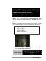
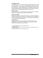
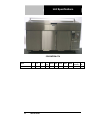
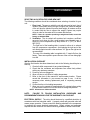
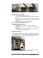
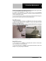
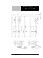
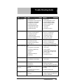
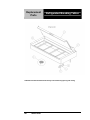
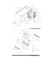
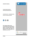
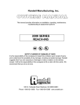
OPERATOR’S MANUAL
This manual provides information on
installation, operating, maintenance,
trouble shooting & replacement parts for
CHICK-FIL-A
REFRIGERATED
BREADING TABLE
52365WPRM-CFA
NOTIFY CARIER OF DAMAGE AT ONCE.
It is the responsibility of the consignee to inspect the
container upon receipt of same and to determine the
possibility of any damage, including concealed
damage. Randell suggests that if you are suspicious
of damage to make a notation on the delivery receipt.
It will be the responsibility of the consignee to file a
claim with the carrier. We recommend that you do so
at once.
525 South Coldwater Road • Weidman, MI 48893
888-994-7636 • Fax 888-864-7636 • unifiedbrands.net
4/17/2014
PP MNL0502 rev E
Table of Contents
page 2………………………………….…………Congratulations
page 3……………………………………Parts & Service Hotline
page 3………………………………...…Serial Number Location
page 4-7……………………………….Randell Limited Warranty
page 8…………………………………………Unit Specifications
page 9……………………………………….........Unit Installation
page 10-12....……………………………………...Unit Operation
page 13-16……………………………..Preventive Maintenance
page 17-18..…………………………………..Electrical Diagram
page 19……………………………………..……Troubleshooting
page 20-23…………………………….……..Replacement Parts
Congratulations on your recent purchase of Randell food service equipment,
and welcome to the growing family of satisfied Randell customers.
Our reputation for superior products is the result of consistent quality
craftsmanship. From the earliest stages of product design to successive steps
in fabrication and assembly, rigid standards of excellence are maintained by
out staff of designers, engineers, and skilled employees.
Only the finest heavy-duty materials and parts are used in the production of
Randell brand equipment.
This means that each unit, given proper
maintenance will provide years of trouble free service to its owner.
2
800-621-8560
In addition, all Randell food service equipment is backed by
some of the best warranties in the food service industry and by
our professional staff of service technicians.
Retain this manual for future reference.
NOTICE: Due to a continuous program of product improvement, Randell
reserves the right to make changes in design and specifications without prior
notice.
NOTICE: Please read the entire manual carefully before installation. If certain
recommended procedures are not followed, warranty claims will be denied.
MODEL NUMBER _________________________
SERIAL NUMBER _________________________
INSTALLATION DATE _____________________
The serial number is located inside the right door on the interior rear
wall of the refrigerated base compartment.
800-621-8560
Randell Service and Parts
Hotline
unifiedbrands.net
3
Warranty Policies
UNIFIED BRANDS/Randell
Chick-Fil-A – Breading Table (Product 52365WPRM-CFA)
EXCLUSIVE OPTIONAL 5-YEAR LIMITED WARRANTY INFORMATION
(U.S & Canadian Sales only)
Randell believes strongly in the products it builds and backs them with the
best warranty in the industry. Standard with every unit comes the piece of mind
that this unit has been thoroughly engineered, properly tested and
manufactured to excruciating tolerances, by a manufacturer with over 30 years
of industry presence. On top of that front end commitment, Randell has a
dedicated network of Authorized Service Agencies around the Country to
assist you with any questions or concerns that may arise after delivery of your
new Randell equipment. To locate the nearest Authorized Service Agency
near you please visit www.unifiedbrands.net. In addition, you can contact our
technical service hotline at 1-800-621-8560 regarding any other questions
regarding service of your Randell equipment.
Limited Warranty Terms
• The Optional 5-Year Limited Warranty Coverage begins at the time of
installation or 3 months from factory shipment, whichever occurs first.
Randell is not responsible for installation delays which may cause the
warranty to be made in effect if the unit is not in use.
•
Warranty work must be performed by the Authorized Service Agencies
or its authorized sub-contractors in the area. Any work performed by a
non-authorized service company voids the warranty.
•
Extended warranty purchases are non-refundable.
.Limited Warranty Coverage
•
The purchase of the Optional 5-Year Limited Warranty, replaces any
standard warranties and can not be added to any other warranty offer.
•
Coverage includes Parts and Labor for any and all parts that fail within
the warranty period, excluding the following wear items**:
•
4
o
Gaskets
o
Condenser Filter
**Coverage includes a single occurrence of a compressor replacement
within the 5-year term. The decision on whether or not to furnish a
complete condensing package in the case of a compressor failure in
order to expedite the repair is at the sole discretion of Randell’s inhouse service support team. The replacement of a complete
condensing package will be considered as a compressor replacement.
800-621-8560
Items Not Covered Under Warranty
• Preventative Maintenance type of repairs such as condenser cleaning,
temperature adjustments, clogged drains, unit leveling, and gasket
replacement (including re-application of silicone), or cleaning.
•
Repairs caused by neglect to follow recommended PM schedule
•
Repairs caused by abuse such as freight damage, or scratches and
dents.
•
Temperature adjustments due to a wide range of ambient conditions
•
Repairs caused by incorrect installation
•
Work performed by a Non-Authorized Service Company
•
Electrical or mechanical component failure due to water damage from
cleaning procedures
•
Food/Product loss
•
Any damaged deemed caused by improper use of or inconsistent with
the design and intended application the equipment.
Specification & Product Design
Due to continued product improvement the specification and product design
may change without notice. Such revisions do not entitle the buyer to
additions, changes or replacements for previously purchased equipment.
WHEN EXPORT WARRANTIES APPLY
1. Randell covers all non-electrical components under the same
guidelines as our standard domestic policy.
2. All electrical components operated on 60 cycle power are covered
under our standard domestic policy.
3. All electrical components operated on 50 cycle power are covered for
90 days from shipment only.
Extended warranty options are not available from the factory
QUOTATIONS
Verbal quotations are provided for customer convenience only and are
considered invalid in the absence of a written quotation. Written quotations
from Randell are valid for 30 days from quote date unless otherwise specified.
Randell assumes no liability for dealer quotations to end-users.
SPECIFICATION & PRODUCT DESIGN
Due to continued product improvement, specification and product design may
change with communication between Randell and Chick Fil A. Such revisions
do not entitle the buyer to additions. Changes or replacements for previously
purchased equipment.
unifiedbrands.net
5
SANITATION REQUIREMENTS
Certain areas require specific annotation requirements other than N.S.F. &
U.L. standards. Randell must be advised of these specifications before
fabrication of equipment. In these special circumstances, a revised quotation
may be required to cover additional costs. Failure to notify Randell before
fabrication holds the dealer accountable for all additional charges.
CANCELLATIONS
Orders
canceled
prior
to
production scheduling
entered into
engineering/production and cancelled are subject to a cancellation charge
(contact factory for details).
STORAGE CHARGES
Randell makes every effort to consistently meet our customer’s shipment
expectations. If after the equipment has been fabricated, the customer
requests delay in shipment, and warehousing is required:
1. Equipment held for shipment at purchasers request for a period of 30
days beyond original delivery date specified will be invoiced and
become immediately payable.
2. Equipment held beyond 30 days after the original delivery date
specified will also include storage charges.
SHIPPING & DELIVERY
Randell will attempt to comply with any shipping, routing or carrier request
designated by dealer, but reserves the right to ship merchandise via any
responsible carrier at the time equipment is ready for shipment. Randell will
not be held responsible for any carrier rate differences; rate differences are
entirely between the carrier and purchaser. Point of shipping shall be
determined by Randell (Weidman, MI/Jackson, MS). At dealer’s request,
Randell will endeavor whenever practical to meet dealer’s request. Freight
charges to be collect unless otherwise noted.
DAMAGES
All crating conforms to general motor carrier specifications. To avoid
concealed damage, we recommend inspection of every carton upon receipt.
In the event the item shows rough handling or visible damage to minimize
liability, a full inspection is necessary upon arrival. Appearance of damage will
require removing the crate in the presence of the driver. A notation must be
placed on the freight bill and signed for by the truck driver at the time of
delivery.
Any and all freight damage that occurs to a Randell piece of
equipment as a result of carrier handling is not considered under warranty, and
is not covered under warranty guidelines. Any freight damage incurred during
shipping needs to have a freight claim filed by the receiver with the shipping
carrier. Consignee is responsible for filing of freight claims when a clear
delivery receipt is signed. Claims for damages must be filed immediately
(within 10 days) by the consignee with the freight carrier and all cartons and
merchandise must be retained for inspection.
6
800-621-8560
RETURNED GOODS
Authorization for return must first be obtained from Randell before returning
any merchandise.
Any returned goods shipment lacking the return
authorization number will be refused, all additional freight costs to be borne by
the returning party. Returned equipment must be shipped in original carton,
freight prepaid and received in good conditions. Any returned merchandise is
subject to a minimum handling charge (consult factory for rate).
INSTALLATION
Equipment installation is the responsibility of the dealer and/or their customer.
Randell requires all equipment to be professionally installed.
PENALTY CLAUSES
Dealer penalty clauses, on their purchase order or contractually agreed to
between the dealer and their clients are not binding on Randell. Randell does
not accept orders subject to penalty clauses. This agreement supersedes any
such clauses in dealer purchase orders.
EXPORT POLICY
All quotations for export sales are handled by International Manufacturer’s
Representatives. Please consult Unified Brands customer service team at
888.994.7636 for additional export information.
*FOOTNOTES IN REFERENCE TO PARAGRAPHS ABOVE
1. Herein called Randell.
2. NET means list price less discount, warranty, labor policy, freight, Randell delivery and other
miscellaneous charges.
CASH DISCOUNTS WILL BE CALCULATED ON NET ONLY.
unifiedbrands.net
7
Unit Specifications
52365WPRM-CFA
Model
52365WPRM-CFA
8
L
D
H
Work
Hgt.
Doors
H.P.
Volts
Amps
NEMA
Storage
(cubic ft)
Ship
Wt.
65"
33"
42"
39"
3
1/2
115
12
5-15P
13.2
740
800-621-8560
Unit Installation
SELECTING A LOCATION FOR YOUR NEW UNIT
The following conditions should be considered when selecting a location for your
unit:
1. Floor Load: The area on which the unit will rest must be level, free of
vibration, and suitably strong enough to support the combined weights
of the unit plus the maximum product load weight. All casters must be
in contact with the floor to support the weight. Casters may require
shims in order for the caster to be in contact with the floor.
NOTE: If there is a question pertaining to weight load limits, consult the
factory at 1-800-621-8560.
2. Ventilation: The air cooled self contained unit requires a sufficient
amount of cool clean air. Also, avoid locating in an unheated room or
where the room temperature may drop below 55° F (13 °C) or about
86°F (32°C).
The right end of the breading table is vented to allow air to exhaust
from the compressor compartment. Avoid placing the right end of the
unit directly against a wall or other surfaces. A 2” gap on the right end is
recommended.
The rear of the breading table is supplied with 1” stand offs from the
factory. These are required to space the rear of the unit from being tight
to a wall.
INSTALLATION CHECKLIST
After the final location has been determined, refer to the following checklist prior to
start-up:
1. Check all visible components for any potential damage
2. Check that the condenser and evaporator fans rotate freely without
striking any stationary members.
3. Power up unit once plugged in.
4. Allow unit time to cool down to holding temperature.
5. Refer to the front of this manual for serial number location. Please
record this information in your manual on page 3 now. It will be
necessary when ordering replacement parts or requesting warranty
service.
6. Confirm that the unit is holding temperature.
7. Allow your unit to operate for approximately 45 minutes before putting
in food to allow interior of unit to cool down to storage temperature.
NOTE: All motors are oiled and sealed.
NOTE:
FAILURE TO FOLLOW INSTALLATION GUIDELINES AND
RECOMMENDATIONS MAY VOID THE WARRANTY ON YOUR UNIT.
ELECTRICAL SUPPLY: The wiring should be done by a qualified electrician in
accordance with local electrical codes. A properly wired and grounded outlet will
assure proper operation. Please consult the data tag attached to the compressor
to ascertain the correct electrical requirements. Supply voltage and amperage
requirements are located on the serial number tag located on the rear interior wall. .
unifiedbrands.net
9
NOTE: It is important that a voltage reading be made at the compressor
motor electrical connections, while the unit is in operation to verify the
correct voltage required by the compressor is being supplied. Low or high
voltage can detrimentally affect operation and thereby void its warranty.
Unit Operation
UNIT INFORMATION
Mechanical Compartment
1. The breading station is supplied with a main power switch.
The switch is located on the rear of electrical box behind
the upper hinged vented door. The main power switch will
completely shut down the upper rail as well as the lower
refrigerated base when in off position.
2. The rail power switch is located on the front of the electrical
box. The rail power switch will shut down the rail for nightly
shut down and cleaning. The lower refrigerated base will
continue to cool when the rail power switch is off.
3. Two digital temperature controls are located on the front of
the electrical box. The upper control regulates temperature
for the rail and the lower control regulates temperature for
the refrigerated base. (See Unit Operation page 11).
4. The condenser filter indicator light is located on the front of
the electrical box. If illuminated the condenser filter must be
cleaned or replaced. (See Preventative Maintenance page
12).
5. The condenser filter is located behind the lower hinged
vented door. (See Preventative Maintenance page 12).
6. The drain valve for the upper rail is found behind the upper
hinged vented door. The rail may be drained by placing a
pan under the drain valve and opening the valve. (See
Evening Shut Down of Prep Rail).
Upper Rail Lid and Lift Mechanism
1. The lid can be positioned three ways
• Fully closed
• Opened
• Fully opened
10
800-621-8560
Note: All cleaning of rail lift mechanism must be done while lid is in closed position. The tension of the
lift mechanism has been pre-set at the factory.
MORNING STARTUP OF PREP RAIL
1. Unit cleaning may be performed at this time.
2. Turn on unit. Power switch for rail is found behind upper hinged vented
door.
3. Allow a minimum 45 minutes for your unit to cool down before loading
product. A uniform frost pattern will appear on side walls and bottom of
prep rail area.
4. Load the product and proceed with food preparation.
Note: Product entering unit must be at 41°F or less .
EVENING SHUT DOWN OF PREP RAIL
1. Remove product from unit at the end of the day’s preparation.
2. Turn off unit
3. Unit cleaning may be performed at this time if the frost has melted off
the surface.
4. Once defrosted, the rail drain may be opened to remove any water that
has resulted from the defrosting procedure.
TEMPERATURE CONTROLS
Your refrigerated breading table is equipped with a temperature adjustment control
for the refrigerated rail as well as a temperature adjustment control for the
refrigerated base which are located inside the mechanical housing behind the
upper hinged vented door.
Figure 1 illustrates the outer panel of the mechanical housing. The upper temperature control is for
the refrigerated rail and the lower temperature control is for the refrigerated base.
unifiedbrands.net
11
Unit Operation - cont.
To raise temperature in the refrigerated rail:
A. Push and hold the “set” button until 34 appears then release the “set”
button. 34 is the current set point temperature.
B. Push and release the up arrow 2 times until 36 is displayed. Push and
release the “set” button one time. The new set point, 36, will flash 3
times and then will be locked in.
To lower temperature in the refrigerated rail:
A. Push and hold the “set” button until 34 appears and then release the
“set” button. 34 is the current set point temperature.
B. Push and release the up arrow 2 times until 32 is displayed. Push and
release the “set” button one time. The new set point, 32, will flash 3
times and then will be locked in.
NOTE: It is recommended to only make changes of 2 degree increments
at a time. Allow for the unit to operate 24 hours between adjustments. If
the 2 degree adjustment is not enough another adjustment can be made.
The maximum highest setting is 38 degrees and the minimum lowest
setting is 28 degrees. If the settings need to go above or below this point
there may be other contributing factors as to the cause of the
temperature variances, please contact the factory at 1-800-621-8560.
To raise the temperature in the refrigerated base:
A. Push and hold the “set” button until 34 appears then release the “set”
button. 34 is the current set point temperature.
B. Push and release the up arrow 2 times until 36 is displayed. Push and
release the “set” button one time. The new set point, 36, will flash 3
times and then will be locked in.
To lower temperature in the refrigerated base:
A. Push and hold the “set” button until 34 appears and then release the
“set” button. 34 is the current set point temperature.
B. Push and release the up arrow 2 times until 32 is displayed. Push and
release the “set” button one time. The new set point, 32, will flash 3
times and then will be locked in.
NOTE: It is recommended to only make changes of 2 degree increments at a
time. Allow for the unit to operate 24 hours between adjustments. If the 2
degree adjustment is not enough another adjustment can be made. The
maximum highest setting is 38 degrees and the minimum lowest setting is
28 degrees. If the settings need to go above or below this point there may be
other contributing factors as to the cause of the temperature variances,
please contact the factory at 1-800-621-8560.
12
800-621-8560
Preventive Maintenance
Randell strongly suggests a preventive maintenance program which would include
the following monthly, weekly, and daily procedures:
If a failure of the equipment is a direct result of any of the Preventative
Maintenance guidelines being neglected, the repairs and parts replacements will
not be covered under warranty.
It is recommended that the customer contact the local Authorized Service Agent to
provide a quote to perform periodic Preventative Maintenance.
Daily PM Procedures:
1. Clean upper lid hinge mechanism on a daily basis with a damp cloth containing
a solution of warm water and mild detergent to remove any debris that may
interfere with the hinge function.
Note: The upper lift mechanism must be cleaned while the lid is in the down
position. Do not lift the lid while cleaning.
Wipe along roller guide as well as the surface of the roller glides
Weekly PM Procedures:
2. Clean all gaskets on a weekly if not daily basis with a solution of warm water
and a mild detergent to extend gasket life.
3. Clean the grease filter on a weekly if not daily basis with either hot water, mild
detergent, or by cycling through a dishwasher.
unifiedbrands.net
13
Monthly PM Procedures:
4. Cleaning of all condenser coils on a monthly basis. Condenser coils are a
critical component in the life of the compressor and must remain clean to assure
proper air flow and heat transfer. Failure to maintain this heat transfer will affect
unit performance and eventually destroy the compressor. Clean the condenser
coils with coil cleaner and/or a vacuum, cleaner and brush. Proper care of the filter
will reduce the need for this task. See item #1.
4A. Open lower louver ventilation door for the compressor compartment
and remove mesh filter to view the condenser coil. Use brush attachment
for vacuum in this area to vacuum all particles out of this area.
NOTE: Brush coil in direction of fins, normally vertically as to not damage or
restrict air from passing through condenser.
4B. Remove 8 phillips screws on right exterior side of compressor
compartment to gain access to condensing unit. Vacuum all loose particles
that can be seen being careful not to damage any wires or copper lines.
Accessing the Mechanical Housing
Step 1: Remove 8 screws.
Step 2: Pull off side panel.
Step 3: Access components.
5. Clean and disinfect rail drains with a solution of warm water and mild detergent
on a monthly basis. It is recommended to open and close the drain valve as the
hot water is flowing through to clean any debris from the internal valve
components.
6. Clean and disinfect drain lines and evaporator pan with a solution of warm water
and mild detergent on a monthly basis. Remove right side access panel on right
end of table. Remove clear plastic drain line from plastic tray of condensing unit
and place pan under end of drain tube. Discard waste water from pan when
cleaning is complete. Re-insert plastic drain tube into position on condensing unit.
7. Inspect all silicone seams at interior of the rail and refrigerated base cabinet on
a monthly basis. Re-apply food grade silicone sealant as needed to any seams
where silicone has peeled away or cracked.
Semi-Annual PM Procedures:
8. For units built after August 28, 2009 with direct pull drain valve. Clean rubber oring seals within drain valve assembly every 6 months by washing with warm
water and mild detergent.
8A. Loosen and remove 4 bolts in drain valve with 5/16” wrench while
holding the nut with 3/8” wrench. Valve will separate into 3 pieces. Carefully
remove o-ring gasket seals for cleaning. Wipe around sealing area of valve to
remove any debris.
14
800-621-8560
8B. Fit o-ring seals back onto valve components. Piece valve together,
insert bolts, apply nuts, and tighten (do not over-tighten)
NOTE: DO NOT USE SHARP UTENSILS FOR ANY OF THE ABOVE
PROCEDURES.
CLEANING AGENT
COMMENTS
Routine cleaning
JOB
Soap, ammonia, detergent Medallion
Apply with a sponge or cloth
Fingerprints and smears
Arcal 20, Lac-O-Nu, Ecoshine
Provides a barrier film
Stubborn stains and
discoloration
Cameo, Talc, Zud, First Impression
Rub in the direction of the
polish lines
Greasy and fatty acids,
blood, burnt-on foods
Easy-Off, Degrease It, Oven Aid
Excellent removal on all
finishes
Grease and Oil
Any good commercial detergent
Apply with a sponge or cloth
Restoration/Preservation
Benefit, Super Sheen
Good idea monthly
Reference: Nickel Development Institute, Diversey Lever, Savin, Ecolab, NAFEM.
NOTE: Do not use steel pads, wire brushes, scrapers, or chloride cleaners
to clean your stainless steel.
CAUTION: DO NOT USE ABRASIVE CLEANING SOLVENTS, AND NEVER
USE HYDROCHLORIC ACID (MURIATIC ACID) ON STAINLESS STEEL.
unifiedbrands.net
15
STEPS FOR REMOVING THE GREASE FILTER FOR CLEANING:
Step 1: Locate grease filter
on the front of the condenser
air in duct. Behind lower hinged
vented door.
Step 2: Locate finger hole
opening to remove filter without
the use of tools.
Step 3: Insert finger and force
filter upwards.
Step 4: Filter should fall
out in your hands.
Step 5: Pull downwards to
release the filter at the top.
Step 6: Filter should fall
out of the top holding bracket.
Step 7: Removing the filter also
also allows access to the
condenser for cleaning.
Proper maintenance of equipment is the ultimate necessity in preventing costly
repairs. By evaluating each unit on a regular schedule, you can often catch and
repair minor problems before they completely disable the unit and become
burdensome on your entire operation.
For more information on preventive maintenance, consult the local ASA or
CFESA member. Most repair companies offer this service at very reasonable
rates to allow you the time you need to run your business along with the peace of
mind that all your equipment will last throughout its expected life. These services
often offer guarantees as well as the flexibility in scheduling or maintenance for
your convenience.
Randell believes strongly in the products it manufactures and backs those products
with one of the best warranties in the industry. We believe with the proper
maintenance and use, you will realize a profitable return on your investment and
years of satisfied service.
16
800-621-8560
Electrical Diagram
Prior to September 2008
unifiedbrands.net
17
Electrical Diagram – cont.
After September 2008
18
800-621-8560
Trouble Shooting Guide
SYMPTOM
POSSIBLE CAUSE
PROCEDURE
Unit doesn't run
1.
2.
3.
4.
5.
6.
7.
8.
No power to unit
Temperature control turned off
Temperature control faulty
Compressor overheated
Condenser fan faulty
Overload protector faulty
Compressor relay faulty
Compressor faulty
1.
2.
3.
4.
5.
6.
7.
8.
Unit short cycles
1.
2.
3.
4.
5.
Condenser coil/filter dirty
Pressure control settings
Condenser fan faulty
Compressor faulty
Overload repeatedly tripping
1. Clean coil/filter
2. 30 cut in / 15 differential
3. Service fan and motor.
4. Call ASA for service
5. Check outlet voltage
Unit runs constantly
Unit not cold enough
Plug in unit
Check temperature control
Test temperature control
Clean condenser coil/filter
Service condenser fan
Test overload
Test relay
Call ASA for service
6. Solenoid not seating
6. Call ASA for service
1. Condenser coil/filter dirty
2. Condenser fan faulty
3. Pressure control settings
4.. Filter light on
1. Temperature control set too
high
2. Temperature control faulty
1. Clean coil/filter
2. Service condenser motor
3. 30 cut in / 15 differential
4.. Clean/change condenser filter
3. Condenser coil/filter dirty
4. Filter light on
5. Air flow
1. Adjust control to lower setting
2. Test control
3. Clean coil/filter
4. Clean/change condenser filter
5. Allow 3” space on right end of
unit for ventilation
6. Refrigerant leaking or
contaminated
6. Call ASA for service
Unit too cold
1. Temperature control set too low
2. Temperature control faulty
1. Adjust control to raise setting
2. Test control
Dixell control errors
1. Flashing “HA”
2. Flashing “P1”
1. High Alarm error
2. Primary probe failure
3. Flashing “P2”
3. Secondary (defrost) probe failure
1. Compressor mountings loose or
hardened.
1. Tighten or replace compressor
mountings
2. Condenser fan damaged or
hitting fan shroud
2. Inspect condenser fan
1. Light on.
1. Clean/replace filter
2. Air flow
2. Allow 3” space on right end
of unit for ventilation
Unit noisy
Filter light
unifiedbrands.net
19
Replacement
Parts
Refrigerated Breading Tables
CAUTION: Hold lid with both hands securely at all times during opening and closing.
20
800-621-8560
unifiedbrands.net
21
ITEM
DESCRIPTION
PART #
1
Hinged Cover with Recessed Handle
RP CVR0701
2
Counter Balance Hinge Lift Assy
HD HNG0501
3
Adapter Grid, 12” x 20”
RP ADP0801
4
Drain Screen, 2”
RP DSN002
5
Elbow, 1 ½” PVC Fem x Glue
PB ELB9905
6
Pipe, 1 ½” PVC
PB PIP150
7
Ball Valve, 1 ½” PVC Female
PB VLV9901
7A
Pull Gate Valve 1 ½” PVC Female (after August 2009)
PB VLV0901
7B
Drain Elbow extension downspout
RP ELB0903
Dixell Digital Control for Base
RP CNT0204
Dixell Probes for Base
RF CNT0505
8
8A
9
Rocker On/Off Switch for Rail
EL SWT0502
10
Dixell Digital Control for Rail
RP CNT0501
10A
Dixell Probe for Rail
RF CNT0505
10B
Dixell Probe for Rail (after Jan 2011)
RF CNT1104
Clean Condenser Indicator Light
EL LGT0305
11
11A
Filter Light Sensor
HD SEN0201
12
Louver Knob, Aluminum
HD PIN0102
13
Louver Door – Top
RP LVR0707
13A
Louver Door – Bottom
RP LVR0708
14
Shelf Pins, Aluminum
HD PIN0102
22
800-621-8560
15
Shelf, 13-1/8” x 25-1/4” Stainless Steel
HD SHL015SS
16
Door Hinge Top/Bottom
HD HNG0706
16A
Door Hinge Self Closure Spring (Bottom Only)
HD HNG0707
17
Toe Style Bracket/Door Handle, Stainless Steel
RP HDL0501
18
Door Gasket
IN GSK1020
19
Evaporator Fan Motor, 120V w/blade
EL MTR2338
20
Temperature Control Probe - Dixell
RF CNT0505
21
Evaporator Condensate Pan, Plastic
RP DRP107
22
Expansion Valve – Rail
RF VLV404
22A
Expansion Valve – Base
RF VLV414
23
Shield Panel for Base Coil Assembly
RP PNL107
24
Evaporator Coil Assembly
RP CSY108SL
24A
Evaporator Coil
RF COI107
25
Solenoid Valve
RF SOL9801
26
Evaporator Fan Shroud
RP SHD107
27
Mounting Support Bracket for Base Coil Assembly
RP SPT0500
28
Door Assembly with Toe Bracket, Right Hinge
RP DOR0708
29
Door Assembly with Toe Bracket, Left Hinge
RP DOR0707
30
Caster, 4-1/2” Overall with locking mechanism
HD CST030
Caster, 4-1/2” Overall without locking mechanism
HD CST031
31
Condensing Unit Shroud
RP HSG0501
32
Magnetic Catch & Bracket Assembly for Louver Door
RP CTH0501
33
Magnetic Catch
HD CTH9901
34
Hinge Bracket, Louver
RP BRK1105
35
Grease Filter, Condenser 9-1/2” x 11” Alum. w/pull handle
HD FLT0701
36
Condensing Unit
RF CON9901
37
Condenser Fan Blade
RF FAN007
38
Condenser Fan Motor
EL MTR302R22
39
Compressor
RF CMP9902P
40
40W shatterproof light bulb
EL LGT200
NS
Sliding make shelf
CFA-SLIDER
30A
unifiedbrands.net
23