1
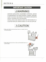
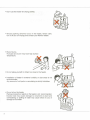
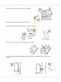
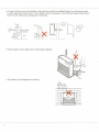
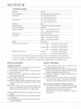
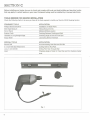
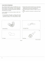
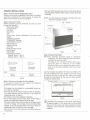
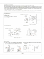
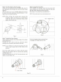
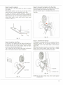
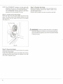
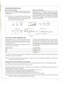
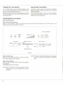
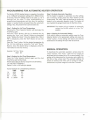
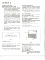
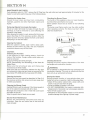
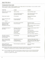
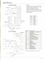
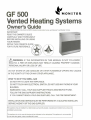
SAFETY ALERT SYMBOL
These symbols appear as important safety precautions and should be understood
and followed by the owner to assure safe operation of the heater.
For Quick Reference
SECTION A: Important Caution
SECTION B: Specifications
Special Features
Safety Features
SECTION C: Tools Needed for Heater Installation
Accessories You May Need
Flue Pipe Extensions
SECTION D: Notice Before Installation
Heater Installation
Flue Pipe Clearances
SECTION E: Gas Connection
SECTION F: Operating Instructions
Starting Instructions
Adjusting Room Temperature
Turning Off the Heater
Relighting the Heater
Programming the Heater
Programming for Automatic Heater Operation
Manual Operation
SECTION G: Protective Features
•
Loss of Power-Automatic Reset
Electrical Fuse
Overheat Prevention
SECTION H: Maintenance and Check
SECTION I: Trouble Shooting Guide
SECTION J : Wiring Diagram
Block Diagram
SECTION K: Parts List
COPYRIGHT © MONITOR PRODUCTS, INC.,
Page
1
5
5
5
6
7
8
9
10
11
15
16
17
17
18
18
18
19
19
20
20
20
20
21
22
23
23
24
SECTION A
IMPORTANT CAUTION
AWARNING
IMPROPER INSTALLATION, ADJUSTMENT, ALTERATION, SERVICE
OR MAINTENANCE CAN CAUSE PROPERTY DAMAGE, PERSONAL
INJURY OR LOSS OF LIFE, REFER TO THE OWNER'S INFORMATION
MANUAL PROVIDED WITH THIS APPLIANCE.
INSTALLATION AND SERVICE MUST BE PERFORMED BY A
QUALIFIED INSTALLER, SERVICE AGENCY OR THE GAS SUPPLIER.
ACAUTION
• Make sure that flue pipe (exhaust pipe, air supply hose) is
connected properly.
• Keep heater clean and do not store any flammable items on or
near the heater.
Don't use the heater for drying clothes.
Should anything abnormal occur in the heater, remain calm,
turn it off (do not unplug) and contact your Monitor dealer.
• Risk of burns.
Flue pipe and louver may have high surface
temperature.
Do not place yourself or others too close to the heater.
• Installation of heater in extreme humidity or dust areas is not
recommended.
Any removal of unit parts or remodeling is strictly forbidden.
Do not sit on the heater.
Placing ornaments or plants on the heater is not recommended.
Excess heat may cause damage to ornament or plant and
overwatering or spilling of water may cause shock to you or
damage to the heater.
Don't spray aerosols on the heater when in operation.
Ei.v
w<t
sf / /
Don't allow children to insert articles in the louvers.
Keep flammable materials, trees, shrubs etc. away from flue pipe.
Do not vent unit into other rooms. Flue pipe must be outside.
Do not install nor exhaust the flue pipe into a crawl space or underneath floor nor into a flue or
chimney.
X
Flue
or
Chimney
In areas of heavy snow accumulation, flue pipe may need to be installed higher to avoid being buried.
In open areas with strong wind, a wind break may be necessary to avoid exhaust gases being blown
back into the intake and causing poor combustion.
24"min
(61cm)
Long —
Extension'
kit
Must be higher.
Snow
Exhaust pipe must be kept clear of flammable materials.
This heater is not designed to be built in.
\
1
SECTION B
SPECIFICATIONS
Model No.
Type of Appliance
Input Rating
Output Rating
Efficiency
Electrical Rating
Power Consumption
Heated Air Delivery
Flue Pipe Hole
Dimensions
Weight
Inlet Gas Supply Pressure
Manifold Test Pressure
GF500
Fan type direct vent wall furnace
Nat. Gas 38,000 BTU/hour
LP. Gas 34,500 BTU/hour
Nat. Gas 30,700 BTU/hour
LP. Gas 27,900 BTU/hour
83%
120V, 60Hz, Less than 2 amperes
80 Watts
High
388 Cubic feet/minute
Low
300 Cubic feet/minute
2.5 inches diameter
Height: 26.6 inches (67.56cm)
Width: 28.7 inches (72.90cm)
Depth: 13.8 inches (35.05cm)
82 pounds
Nat. Gas Max. 10.5 inch W.C. (267 mmH2O)
Min.
5.1 inch W.C. (130mmH2O)
LP. Gas Max. 13.0 inch W.C. (330 mmH2O)
Min. 11.0 inch W.C. (279 mmH2O)
Nat. Gas
3.4 inch W.C. (85 mmH2O)
LP. Gas
3.4 inch W.C. (86 mmH2O)
The minimum and maximum inlet gas supply pressure are for the purpose of input adjustment.
The efficiency rating of this appliance is a product of thermal efficiency rating determined under
continuous operating conditions and was determined independently of any installed system.
SPECIAL FEATURES
SAFETY FEATURES
AUTOMATIC IGNITION
MEMORY BACK UP: Set memory can be kept in case of
power failure for up to 5 minutes.
DUAL BLOWERS: Separate fans for combustion and
room air circulation.
THERMOSTATICALLY CONTROLLED: Adjusts to the
desired room temperature.
BUILT-IN TIMER: Heater will automatically operate as
programmed by the user.
AUTOMATIC RESET AFTER POWER FAILURE: Heater
will automatically resume operation after power is
restored.
INDICATOR LIGHTS: Easy-to-see signals show when
heater is in operation, when timer is activated, and
when the burner is operating in low or high modes.
SAFE RE-LIGHTING: Heater will not restart until its
combustion chamber has cooled.
ELECTRICAL PROTECTION: Heater automatically shuts
off in the unlikely event of a malfunction in the electrical
circuitry or disruption of the power supply.
NO EXHAUST IN ROOM: Products of combustion are
discharged outdoors.
FLUE PIPE: Outside air is drawn through a pipe-withina-pipe venting system. This process preheats
combustion air and regains heat from exhaust gases.
CLEAN OPERATION: Products of combustion are vented
outside.
CONSUMES NO ROOM AIR: Air for combustion is drawn
from outside.
EASY INSTALLATION: Includes all parts required for
standard installation.
A
CAUTION: ALTERNATE POWER SOURCES
The Monitor GF500 may not operate when powered
by sources such as an auxiliary generator, UPS
(Uninterrupted Power Source), inverters, etc.
Check with your dealer for guidance on specific
applications.
SECTION C
Before installing your heater, be sure to check and comply with local and state building and electrical codes
that may apply to vented heaters in your area. Permanent wiring must be installed by a licensed electrician.
TOOLS NEEDED FOR HEATER INSTALLATION
Check the following charts to be sure you have all the tools required to install your Monitor GF500 Heating System.
STANDARD TOOLS
Phillips Head Screwdriver
Steel Tape Measure
Pen or Pencil
Exterior Caulk
Yardstick or Long Straight Edge
Soapy Water
APPLICATION
Installation of Heater Parts
Taking Measurements
Marking Drilling Location
Caulking Between Packing and Wall
Checking Angle of Hole for Flue Pipe
Lubricating Sleeve Hardware
SPECIAL TOOLS
Electric Drill
2 1/2 inch Hole Saw Attachment
Long 1/4 inch Drill Bit
Level
APPLICATION
Accommodating Hole Saw and Drill Bit
Cutting Hole for Flue Pipe
Drilling Pilot Hole Through Wall
Checking Angle of Hole for Flue Pipe and for checking heater
level.
Fig.1
ACCESSORIES YOU MAY NEED
Check the list below and see your MPI dealer for accessories you may need or want for installation of your heating
system.
ACCESSORY
Medium Flue Pipe
Long Flue Pipe
P/N 8206
P/N 8005
Extra Short, Short, Medium or
Long Extension Kit or Elbow Adapter kit
(See Flue Pipe Extensions, page 8)
APPLICATION
For use where wall thickness is up to 14Va inches (36.83cm)
For use where wall thickness is up to 20'/2 inches (52.07cm)
For use where "standard" installation is not practical
FLUE PIPE EXTENSIONS
Four standard extension kits are available from your
Monitor dealer. Most installations can be made with
one of these kits. In special cases, custom installations
may be required. These may be made with components
purchased from your dealer.
In any installation the following limitations MUST NOT
BE EXCEEDED:
2. These elbows should include the one used at the
heater but not the one on the air supply hose nor the
integral bends in the flue pipe. (See Figure 2)
3. The correct damper as shown on Page 13 must be
used.
4. Follow carefully the instruction included with each
kit.
1. The total length of the intake or exhaust pipe should
not exceed 10 feet (3.05m) with 3 elbows, 13 feet
(3.96m) with 2 elbows, or 161/2 feet (5.3m) with 1 elbow.
Exhaust Elbow
Air Supply Hose
90° Joint
Flue Pipe
* Do not count
Fig. 2
SECTION D
NOTICE BEFORE INSTALLATION
The heater must be installed by a qualified service
person according to this installation instruction .
The installation must conform with local codes or, in the
absence of local codes, the National fuel Gas Code,
ANSI Z223.1 .
The installation must conform with local codes or, in the
absence of local codes, the current CAN 1-B149
INSTALLATION CODE.
For mobile housing and recreational installation the
current Standard CSA Z 240.4 GAS EQUIPPED
RECREATIONAL VEHICLES AND MOBILE HOUSING.
A manufactured home (mobile home) installation must
conform with the Manufactured Home Construction
and Safety Standard, Title 24 CFR, Part 3280, or, when
such a standard is not applicable, the Standard for
Manufactured Home installations, ANSI A 225.1/NFPA
501 A.
Due to high temperatures the appliance should be
located out of traffic and away from furniture and
draperies.
Children and adults should be alerted to the hazards of
high surface temperatures and should stay away to
avoid burns or clothing ignition.
Young children should be carefully supervised when
they are in the same room as the appliance.
Clothing or other flammable material should not be
placed on or near the appliance.
Make sure that the flow of combustion and ventilation
air not be obstructed.
Any safety or guard removed for servicing an appliance
must be replaced prior to operating the appliance.
A\ WARNING
Do not operate appliance with the panel removed,
cracked or broken. Replacement of the panel should be
done by a licensed or qualified service person.
For manufactured home (mobile home) or residential
installation convertible for use with natural gas and liquefied
petroleum gases when provision is made for the simple
conversion from one gas to the other.
Installation and repair should be done by a qualified
service person. The appliance should be inspected
before use and at least annually by a qualified service
person. More frequent cleaning may be required due to
excessive lint from carpeting, bedding material, etc. It is
imperative that control compartments, burners and
circulating air passageways of the appliance be kept
clean.
Do not use this heater if any part has been under water.
Immediately call a qualified service technician to inspect
the heater and to replace any part of the control system
and any gas control which has been under water.
The appliance, when installed, must be electrically
grounded in accordance with local codes or, in the
absence of local codes, with the National Electrical
Code, ANSI/NFPA 70.
The appliance, when installed, must be electrically
connected and grounded in accordance with local codes
or, in the absence of local codes, with the current CSA
C22.1 CANADIAN ELECTRICAL CODE.
A WARNING
THIS APPLIANCE IS EQUIPPED WITH A THREE-PRONG
(GROUNDING) PLUG FOR YOUR PROTECTION
AGAINST SHOCK HAZARD AND SHOULD BE
PLUGGED DIRECTLY INTO A PROPERLY GROUNDED
THREE-PRONG RECEPTACLE. DO NOT CUT OR
REMOVE THE GROUNDING PRONG FROM THIS PLUG.
A\ WARNING
IN MANUFACTURED/MOBILE HOMES WIRED FOR
120/240V, ENSURE THAT THE GF500 IS ONLY
PLUGGED INTO A 120 VOLT CIRCUIT.
A CAUTION
Before converting the GF500 gas type (to Liquid
Propane or Nat Gas), Read instructions in Section E,
Page 15.
HEATER INSTALLATION
Step 1: Fill Out Owner Registration Card
Remove your owner registration card from the plastic
envelope containing the owner's guide. It should be
filled out and mailed as soon as possible.
Step 2: Check for Parts
Before discarding packing materials, be sure you have
located the following:
Manual Gas Valve
Conversion Kit
Flue Pipe
Sleeve Nut
Tray
Room Temp. Sensor (attached to the rear of the
heater)
Cardboard Template
"STANDARD" Damper
"EXTENSION" Damper
Wall Clamps (2)
Rubber Packing
Joint Pipe
Cloth Insulation Cover
Outer Flange
Pipe Holder
Small Bag of Screws
Tapping, Type A - #8x 3 A
Tapping, Type A - #8x5/ie
(fa^S>
For securing
sleeve and
wall clamps
For securing
wall clamps
SIZE
#8 X 3/4
#8 X 5/16
Tapping
Tapping
Fig. 3
Step 3: Choose a Location for Your Heater
In choosing a location for your heater, the following
guidelines must be considered:
•The heater may be installed on combustible flooring on
the metal tray provided.
•The area around the heater should be free of obstacles
that might interfere with the free flow of air. Allow the
clearances shown in Figure 4.
•The heater must not be installed in a fireplace.
•An AC wall outlet must be within reach of the heater's
power cord. Extension cords must not be used.
•The area outside where the flue pipe will emerge should
be free of foliage, fuel storage tanks and flammable
objects. Air should circulate freely in the area. Allow the
clearances shown in Figure 6 on the next page.
•Refer to Figure 4 to provide adequate accessibility clearances
for servicing.
10
•The wall where flue pipe hole will be cut should be free of
plumbing pipes, electrical wires, studs, air ducts and other
obstacles.
NOTE: L/se the cardboard template provided with your
heater for flue pipe location.
24" (61cm)
(15.24cm)
Fig. 4
Step 4: Drill a Pilot Hole
NOTE:The following directions apply to "standard"
installation. For other methods, follow instructions
included with accessory kits.
For walls up to 8Y2 inches (21.59cm) thick, use a
short flue pipe; for walls up to 141/^ inches
(36.83cm) thick, use a medium flue pipe; and for
walls up to 20 inches (50.80cm) thick use a long
flue pipe.
Use the template to position the hole to be drilled. The
"blue dot" indicates the exact center of the hole. Using
an electric drill and a long drill bit, make a pilot hole
through the wall (Figure 5). Be sure the hole extends
through the outside wall.
Positic n nf |-inle>
—Template
TiMfun m Mum OUT nn
t Jl NMK «*> HCfflK.
rjs;sr.rjst*i«r?.
M»<MfM».
<>
TKAt
RatllUI!-^*
Fig. 5
^CAUTION: The opening on the inside wall should
be approximately '/4 inch higher than on the outside
wall so the flue pipe will slope downward when
installed. This will allow condensation to drain
outdoors.
FLUE PIPE CLEARANCES
• Vent terminal must be located at least 3 feet above any forced air inlet located within 10 feet.
• The vent terminal of a direct vent appliance with an input of 50,000 Btu per hour or less shall be located at least 9
inches from any opening through which flue gases could enter a building, and such an appliance with an input over
50,000 Btu per hour shall require a 12-inch vent termination clearance. The bottom of the vent terminal and the air
intake shall be located at least 12 inches above grade.
• Flue pipe installations should provide for venting to a confined space through which there is a free flow of outdoor
air. Clearances to adjacent walls or obstacles must comply with the requirements shown below.
Frontal Clearance
CAUTION :
A
Do not attach anything onto the outlet
P.nmhi istihle iiiiiiiii
iiimui miummi inn it
* -Wall
24 (60cm)
or more
of the flue pipe.
Any construction
above Flue Pipe
must not come
within 24" (60cm)
of front obstacle
1
5 A"
(14
cm)
5 \/(13.5cm)
^^
Wai
Clamp
|E1
12" (30cm)
or more
I
Ground or slab surface
=^* A
Heater
Overhead Clearance
Side Clearance
Non-combustible
Combustible ->imwmi
-Wall
24' (6Ocm)
or more
3
~or4
24" (60cm) - —»
more
or more
Front Obstacle
3^-t.,, Flue Pipe
r*^
»
5^" J
(13.5cm)
| _J^;
Wall
Clamp '.
Heater - j
*
,,7
//"
i-
1
&^
r*l
J
'Jr
45° /
£
Wall
Combustible
Clamp
|
Side obstacle
'
Ul
24" (60cm)
or
more
1
—
12" (30cm)
or more
i
Flue Pipe
iH P""3 *~~
^J
Heater-
18' (45cm)
or more
,
Flue Pipe
wan
' .
Ground or slab surface
IMPORTANT:
(1) In areas of heavy snow falls, ground surface clearance
must be increased according to average snow falls, to
prevent flue pipe from being buried.
(2) In open area with strong wind, a wind break may be
necessary.
j— 24"min -*.
(61cm)
Extension
kit
-f
Must be higher.
Snow
Fig. 6
11
Step 5: Cut the Hole for the Flue pipe
Using a hole saw attachment and an electric drill, cut a 21/2
inch diameter hole through the inner and outer walls
figure 7).
After the hole is cut, use a straight edge and a level to
be sure the inside opening is approximately 1A inch
higher than the outside opening.
Step 6: Install the Flue Pipe
From INSIDE the building, insert the flue pipe (with
arrow pointing "up") into the hole. Fasten the flue pipe
with the 3 #8x3A tapping screws (Figure 8).
(See Figure 3 for screw size and application.)
NOTE: Top center port is an extra exhaust port.
NOTE: After cutting the inside wall, remove the
insulation. Make sure there are no obstructions
inside the wall, such as electrical wiring, water
pipes, hot air ducts, etc.
tapping screw
Wall
(0.64cm)
Fig. 8
Fig. 7
Step 7: Install the Outer Flange
Apply caulking material to the inside ridge of the rubber
packing (Figure 9).
Holding the "Up" mark to the top, slide the rubber
packing onto the sleeve (caulk side to the wall).
Recommended caulking material Type:
Permatex, RTV Red, Part No. 26C.
NOTE: If it is difficult to slide the packing onto the
sleeve, apply soapy water to the inside of the
packing.
Once the rubber packing is in place, slide the outer
flange onto the sleeve with the conical side pointing
outward (Figure 10).
Screw the flue pipe nut onto the flue pipe grooves, and
tighten it firmly (Figure 10).
Rubber Packing
Flue Pipe Nut.
Outer Flange
Fig. 10
12
Fig. 9
Step 8: Level the cabinet
Place the tray on the floor where you plan to located
your heater.
Position the heater on the tray so the legs of the
cabinet fit into the circular indentation in the tray.
In order for heater to operate properly. It must be
positioned on a level surface. Ensure proper leveling by
adjusting each leg and by using a carpenters level to
check both side to side, and front to back level
condition. (Figure 11)
Legs
Step 10: Connect the Heater to the Flue Pipe
Move the heater toward the wall, guiding the joint pipe
into the center port of the flue pipe (Figure 13).
Be sure the joint pipe is completely inserted into the
flue pipe.
Tray
Fig. 13
Fig. 11
Step 9: Install the Joint Pipe
At the rear of the heater, slide the large end opening of
the joint pipe into the exhaust port outlet of the heater.
Be sure the joint pipe is fully seated. Slide the fabric
cover over the joint pipe (Figure 12).
The o-rings that seal the joint pipe may be dry and
tight. A little soapy water will ease installation.
Step 11: Install the Air Damper
If installation is standard (that is no extension kits are
required), place the air damper marked with a
"STANDARD" over the air intake flange on the flue pipe
(Figure 14).
Place the hose band around the end of the air supply
hose. Push the air supply hose onto the air intake
flange and secure the hose with the hose band.
Fabric Cover
Air Damper
Joint Pipe
Air Supply Hose
Fig. 14
Fig. 12
NOTE: Do not place intake hose onto metal capped
exhaust port.
13
NOTE: The "STANDARD" damper is to be used with
extension kits up to a total overall length of 20
inches and a maximum of 3 bends (90° elbow).
The "EXTENSION" damper must be used when
extension kit or kits exceed 20 inches.
Step 14: Recheck the Heater
Before proceeding, check again to be sure there are no
flammable materials close to the heater. Check to be
sure the heater is level.
Examine the flue pipe to be sure connections are tight.
Step 12: Install the Flue Pipe Holder
Place the ring of the flue pipe holder around the flue
pipe. The other side of the holder hooks in a slot
directly above the joint pipe at the rear of the heater
(See Figure 15).
Flue Pipe Holder
i WARNING: Failure to position the parts in accordance
with these diagrams or failure to use only parts specifically
approved with this appliance may result in property damage
or personal injury.
Fig. 15
Step 13: Secure the Heater
Insert the narrow ends of the 2 wall clamps into sockets
on the rear of the heater.
Loosen the adjustment screws and extend the clamps
until they touch the wall. Fasten the clamps to the wall
with 2 #8x3A tapping screws.
14
SECTION E
GAS CONNECTION
1. The gas supply line shall be gas-tight, sized and so
installed as to provide a supply of gas sufficient to
meet the maximum demand of the heater without loss
of pressure.
2. A shut off valve should be installed in the upstream of
the gas line to permit servicing.
3. Flexible pipe and any appliance connector valve used
for gas piping shall be types approved by nationally
recognized agencies.
4. Any compound used on the threaded joint of the gas
piping shall be a type which resists the action of
liquefied petroleum gas.
5. Supplied gas pressure must be within the limits shown
in the specifications.
6. After completion of gas pipe connections, all joints
including at the heater must be checked for gastightness by means of leak detector solution, soap
and water, or an equivalent nonflammable solution, as
applicable.
CAUTION: Since some leak test solutions, including
soap and water, may cause corrosion or stress
cracking, the piping shall be rinsed with water after
testing, unless it has been determined that the leak
test solution is noncorrosive.
7. The appliance and its appliance main gas valve must be
disconnected from the gas supply piping system during
any pressure testing of that system at test pressures in
excess of 1/2 psi(3.5kPa).
The appliance must be isolated from the gas piping
system by closing its equipment shutoff valve during
any pressure testing of the gas supply piping system
at test pressure equal to or less than 1/2 psi(3.5kPa).
8. A 1/8" test plug is provided for testing of manifold
pressure see schematic for location (page 26)
At time of installation installer must supply a 1/8"
N.P.T. plugged tapping, accessible for test gauge
connection, immediately upstream of the gas supply
connection of the appliance.
9. The minimum and maximum inlet gas supply pressure
are for the purpose of input adjustment.
GAS CONVERSION
Conversion should only be performed by a qualified
Monitor GF service technician.
The conversion shall be carried out in accordance with
the requirements of the provincial authorities having
jurisdiction and in accordance with the requirements of
the CAN 1-B149.1 and .2 installation code.
CAREFULLY
FOLLOW
THE
COMPLETE
CONVERSION INSTRUCTIONS CONTAINED IN THE
CONVERSION KIT SUPPLIED WITH THE GF500.
HIGH ALTITUDE INSTALLATION
All units must be installed according to the following chart
to determine which orifice will be used for the appropriate
altitude
*Obtain the High altitude orifice from your Dealer
1
/2" Threaded connection
Natural Gas
Up to 2000 feet
2000-6000 feet
Do not Change the orifice. (3,50mm)
*3.35mm drill size orifice
Liquid Propane
Up to 2000 feet
2000-6000 feet
Do Not Change the orifice. (2.64mm)
*2.53mm drill size orifice
Gas Piping
Gas Inlet
Manual Gas Valve
Fig. 16
15
SECTION F
FOR YOUR SAFETY READ BEFORE OPERATING
WARNING: If you do not follow these instructions exactly, a fire or explosion may result causing property
damage, personal injury or loss of life.
A. This appliance does not have a pilot. It is equipped
with an ignition device which automatically lights the
burner. Do not try to light the burner by hand.
B. BEFORE OPERATING smell all around the appliance
area for gas. Be sure to smell next to the floor
because some gas is heavier than air and will settle
on the floor.
WHAT TO DO IF YOU SMELL GAS
• Do not try to light any appliance.
• Do not touch any electric switch; do not use any
phone in your building.
• Immediately call your gas supplier from a neighbor's
phone. Follow the gas supplier's instructions.
• If you cannot reach your gas supplier, call the fire
department.
C. Use only your hand to push in or turn the gas control
knob. Never use tools. If the knob will not push in or
turn by hand, don't try to repeat it, call a qualified
service technician. Force or attempted repair may
result in a fire or explosion.
D. Do not use this appliance if any part has been under
water. Immediately call a qualified service technician
to inspect the appliance and to replace any part of
the control system and any gas control which has
been under water.
OPERATING INSTRUCTIONS
STOP! Read the safety information above on this label.
1. Set the thermostat to lowest setting.
2. Turn off all electric power to the appliance via the
ON/OFF switch on the control panel.
3. This appliance is equipped with an ignition device
which automatically lights the burner. Do not try to
light the burner by hand.
4. Turn manual valve at rear of unit clockwise to the full
OFF position.
5. Wait five (5)minutes to clear out any gas. Then smell for
gas, including near the floor. If you then smell gas, STOP!
Follow "B" in the safety information above on this label.
If you don't smell gas, go to next step.
6. Turn manual gas valve to the full ON position. ^
7. Turn on all electric power to the appliance.
8. Set the thermostat to desired setting.
9. If the appliance will not operate, follow the Instructions
"To Turn Off Gas To Appliance" and call your service
technician or gas supplier.
TO TURN OFF GAS TO APPLIANCE
1 .Turn off electric power to the appliance using the ON/OFF switch located on the front of unit.
2. Turn manual valve clockwise to the full OFF position. /">
NOTE: The fan will continue to operate until the appliance is cool, do not turn the appliance off by unplugging it from
the wall.
Unplug the appliance only after unit is cooled down.
16
STARTING INSTRUCTIONS
•Step 1: Plug in the Heater
Plug in the AC cord, and route it away from the area of the
flue pipe. It is recommended that no other appliance share
the same outlet.
NOTE: When the unit is operated for the first time or the
gas piping is replaced, the unit may not come ON
the first few times since air is in the piping. In this
case, repeat the starting procedures.
RI IM
AUT«
ECONOMY
PLUb
Step 2: Set "ON" Button
Depress the operation button to put it in the "ON"
position(Figure 17 ). The "RUN" Lamp lights indicating
"Set Room Temperature" and "Present Room Temperature".
Burner status lamps will light and ignition will start after
approximately 20 seconds. In 30 seconds the circulation
fan will start to operate, and warm air will be felt coming
through the cabinet grill.
BURNER STATUS
_:=
OPERATION
ON/OFF
TIMER SELECTOR
CLOCK
AUTO ECONOMY SET 1s, 2nd 3rd 4th
PLUS
*^« ••« ^«« m^mm mmm
a
ItMH
SET
_ _
ROOM
_ —j
TIME/TEMP SET
T|MF|
' <Mc.\
WOMR MINI ITF SFT r LEAR
| HOUR MINU I b ot I
en a cu a
Fig. 17
ADJUSTING ROOM TEMPERATURE
Pressing either the "Up" or "Down" button will increase or
decrease the set temperature by 2 degree increments.
Once desired temperature is displayed, press set button
to lock into memory.
The lights on the control panel will indicate the level of
heater operation—low or high.
The heater will automatically change its heat output until
the desired room temperature is reached. While it cycles,
you may hear the circulation fan change speed.
Depending on the output required to maintain the desired
room temperature, the indicator lights will illuminate in the
following pattern:
BURNER MODE
LIGHT PATTERN
High
Low
Off
4 indicators—On
2 indicators—On
*No lights on
*The heater will shut itself off temporarily when the desired room temperature has been reached and restart automatically when
necessary to maintain room temperature.
NOTE: The heater may display room temperature 4 degrees above set temperature, depending on heater load
conditions, before shutting itself off.
INSTRUCTIONS FOR ECONOMY PLUS MODE
To engage the economy plus mode, simply press down the button labeled "Economy Plus", to disengage press again.
NOTE: Operation switch must be "ON" and in manual mode.
This feature minimizes the "ON" and "OFF" cycling of the unit by allowing it to overshoot the set temperature by 12
degrees instead of the normal 4 degrees.
The advantages of this feature are to increase the overall efficiency of the unit by:
1. Reducing heat loss during the prepurge and postpurge cycles.
2. Reducing inefficient combustion associated with start up and shut down.
3. Prolonging component life by decreasing expansion and contraction of internal parts.
NOTE: This feature could be compared to driving an automobile in stop and go traffic (regular mode) versus highway
driving with cruise control engaged (Economy Plus mode).
17
TURNING OFF THE HEATER
RELIGHTING THE HEATER
To turn off the heater, press the Operation Button to put
it in the "Off" position (Figure 17). The operation light
will go out, and the fuel flow will stop.
After turning heater off the fans will continue to run until
unit has cooled down to the point where the fans will
automatically stop.
Automatic controls prevent your heater from relighting
after the Operation Button has been set to "Off" until
heater has cooled.
If the Operation Button is put in the "On" position
during the cooling period, the heater will automatically
relight at the end of the period.
PROGRAMMING THE HEATER
SETTING THE CLOCK
Step 1: Set the Timer Selector
Press the "Timer Selector" button, at which time the "Clock Set" Light will illuminate. The LED indicator in the
Display Window will show 88:88 at this point.
DISPLAY WINDOW
RUN
AUTO
EC
?n?QMY
r
BURNER STATUS
_
l_Uo
AUTO
J ROOM
• n n
TIME/TEMP SET
OPERATION
ON/OFF
SET
TEMP
AM
PM
TIMER SELECTOR
CLOCK
ECONOMY
SET 1st
2nd 3rd 4th
HOUR MINUTE SET CLEAR
EH
TEMP|
|
CH EH EH
UP DOWN
EH
TIMER SELECTOR
Fig. 18
Step 2: Set the Hour
Press the "Hour" Button until the correct hour (either
A.M. or P.M.) appears in the window.
Step 3: Set the Minute
Press the "Minute" Button until the correct time appears
in the window.
Immediately press the "Set" Button.
NOTE: If the "Set" Button is not pressed within 1 minute
after the time is set, the programming will be
cancelled.
18
NOTE: The "Hour" and "Minute" Buttons can be pressed
and held or pressed momentarily to change the
time.
PROGRAMMING FOR AUTOMATIC HEATER OPERATION
The Monitor GF500 Heating System is capable of providing
up to 4 different temperature settings for 4 different times
of the day. Not all 4 settings have to be used; 2, 3 or 4
settings can be used. A clear understanding of
programming temperatures and time from the previous
pages is needed before programming the automatic
settings. Also, the present time must have been set.
Step 1: Setting the 1 st Time/Temperature
Pressing the Timer Selector Button will illuminate the
Time/Temp Light.
Press the "Time" Button. Set the 1st desired time by
pressing the "Hour" and "Minute" Buttons as described
under, "Setting the Clock". Once the desired time "AM or
PM" is displayed, press the "Set" Button to lock into
memory.
Press the "Temp" button. Set the desired temperature for
the 1st time setting by using the "Up" and "Down"
Buttons. Once the desired temp is displayed, press the
"Set" Button to lock into memory.
Example: 1 st Time / Temp
SAM 60°
Step 2: Setting the 2nd Time/Temperature
Press the Timer Selector Button again and the 2nd
Time/Temp Light will illuminate.
Follow same steps as above, except for 2nd time/temp.
(ie; 2nd 5PM 74 Degrees)
Repeat if a 3rd or 4th setting is desired.
Step 3: Activate Automatic Operation
For the heater to operate on automatic once the settings
are in memory, simply press the "Auto" Button on the
control panel. The "Auto" Light will illuminate to confirm the
heater is in the automatic operation mode. The heater will
now maintain the programmed temp for that time of day.
IMPORTANT: The heater will not operate in automatic
unless the On/Off switch is in the "On"
position.
Step 4: Clearing An Automatic Setting
If you wish to clear any automatic setting, press the Timer
Selector Button to the appropriate setting and press the
"Clear" button. A new setting will need to be entered
otherwise the old setting will return after 30 seconds.
MANUAL OPERATION
To deactivate the automatic operation, simply press the
"Auto" Button. The "Auto" Light will no longer be
illuminated and the heater will run on a manual setting. This
setting will be determined by the previous auto setting for
that time of day, unless reset. The automatic settings will
remain in memory even if the unit is running in manual,
unless there is a power outage for more than 5 minutes.
Typical Example of a 4-time/temp selection:
TIME
TEMP
1st
SAM
60°
2nd
5PM
74°
3rd
11PM
70°
4th
5 : 30AM
76°
19
SECTION G
PROTECTIVE FEATURES
OVERHEAT PREVENTION
LOSS OF POWER-AUTOMATIC RESET:
NOTE: If power to the heater is interrupted, a thud-like
noise may be heard in the combustion chamber.
This is normal, and should not cause alarm.
For power interruptions of up to 5 minutes, the
set memory is kept and will resume operation
automatically with the set memory.
For power interruptions beyond 5 minutes, your
heater will resume operation (after a 6 minutes
cool down period) in the MANUAL mode and
maintain room temperature according to the
setting temperature you've selected by using the
slide selector for the reset temperature at the
lower right hand side of the cabinet (Figure 19).
When the TIME Button is pressed or the TIMER
SELECTOR Button is pressed to illuminate the
CLOCK SET Light, The Display Window will
show 88 : 88 indicating the need to reset the
clock and re-program the heater for automatic
operation.
If your heater overheats, a thermostatic switch will
automatically stop the flow of gas and extinguish the
flame. The Burner status indicators are blinking.
Restore heater operation by following the steps below.
NOTE: Other symptoms listed in the trouble shooting
chart may cause burner status indicators to
blink, besides an overheat situation.
REMARK: In order to display reset temperature,
it should be set before the heater is plugged in
and energized.
New reset temperature selected after plugged in
will take effect only after a power loss, greater
than five minutes.
Step 1: Turn the Heater Off
Press the Operation Button to put it in the "Off" position.
Step 2: Allow the Heater to Cool
Wait approximately 30 to 45 minutes for the heater to
cool completely.
Step 3: Unplug the Heater from the Wall Outlet.
Step 4: Remove Obstructions
The overheated condition may be caused by obstructions
blocking the air flow to the heater. Check:
• The front of the heater.
• The circulation fan (on the back of the heater).
• The flue pipe (outside).
Step 5: Remove the Louver
Remove the screws at the louver, and carefully remove
the louver (Figure 20).
Louver
RESET TEMPERATURE
50 52 54 56 58 60 62 64 66 68 70 72 74 76 78 80
(TO.
Fig. 19
ELECTRICAL FUSE
In the unlikely event of a failure in the heater's electrical
system, a fuse will "blow" and interrupt the power. Do
not attempt to change the fuse.
Contact your MPI dealer for the name of a trained and
certified service representative in your area.
NOTE: Using a surge protector can minimize the chances
of a blown fuse or PCB failure caused by power
surges.
Remove any accumulation of dust or other matter that
may be covering the burn chamber and the heat
exchangers inside the heater.
Step 6: Replace the Louver
Step 7: Plug in the Heater
Step 8: Re-program the Heater
Step 9: Turn Heater On
fi\CAUTION:
20
If the unit overheats a second time, turn it
off and contact your MPI dealer for
service.
SECTION H
MAINTENANCE AND CHECK
Push operation switch to "OFF" remove the AC Plug from the wall outlet and wait approximately 30 minutes for the
heater to cool before performing any of the following steps.
Checking the Heater Area
Should be kept clean and free from combustible
materials, gasoline and other flammable vapors and
liquids.
Retrieving Objects from Inside the Heater
Should an object fall inside the heater, through the grill
openings, it must be removed to avoid affecting the
operation of the heater.
After allowing the heater to cool, remove the front cover
panel. (See Step 5 of the previous section.) After the
object has been removed, replace the front cover before
attempting to re-start the heater.
Checking the Burner Flame
The burner of this appliance does not need cleaning,
but check the burner flame once a year.
Flame pattern should be as shown in the following
figures.
The burner must flame evenly over the entire surface
when operating correctly. The flame must burn with a
clear blue stable flame.
Blue Flame
SATISFACTORY
Cleaning the Cabinet
When the cabinet is soiled, wipe it with a damp cloth.
Restore the shine with a dry cloth. The use of abrasive
household cleaners may dull the finish.
CAUTION:
Checking the Flue Pipe
At the beginning of each heating season, check the
inside of the flue pipe. Foreign matter, spider webs, etc.
must be removed.
Be sure all fittings and joints are tight.
NOTE: Reassembly and Reseating of the Vent-Air
Intake Pipes
Make sure that all exhaust pipe and intake pipe
connections are firmly mated.
Make sure that the connections between the flue pipe
and exhaust/air intake pipe and hose are secured by the
pipe holder (P/N 4006) and the hose band (P/N 4008).
Cleaning the Interior
Remove the front over panel (as described in Step 5 of
the previous section), and vacuum and wipe away dust
or other accumulation.
Cleaning the Blower Guard
Heating efficiency will be reduced if the blower guard at
rear of the cabinet is blocked with dirt or dust.
Blockage also produces a rise in heat that could cause
the heater to shut off.
Wipe the guard clean at least once a week.
Yellow Flame
UNSATISFACTORY
Fig.21
Cleaning the Burner
Cleaning the burner requires disassemble of the heat
exchanger and combustion chamber.
/K WARN ING:
Do not attempt to disassemble the heat exchanger and
combustion chamber. This work is critical and must be
done only by an authorized technician.
Storing the Heater
During summer months or long periods when your
heater will not be in operation, take the following steps:
• Clean off the exterior cabinet with a damp cloth, and
brush or vacuum dust from the grills.
• Cover the heater to protect it from dust.
• DO NOT DISASSEMBLE the heater or extension kits.
Replacement of lost parts is an unnecessary expence.
• Shut off fuel supply to unit.
• Disconnect or shut off power supply to unit to prevent
possible damage from lighting or power surge.
Electric Motor Maintenance
Motors are permanently lubricated and need no
lubrication. Keep fan and motor free of dust and dirt
clean annually.
21
SECTION I
TROUBLESHOOTING GUIDE
Should symptoms appear during the operation of your heater, refer to the chart below. If you are unable to restore
normal operation, contact your MPI dealer for service.
SYMPTOM
CAUSE
REMEDY
Heater does not go on with
operation switch.
Timer is in Auto.
Press Auto Button again.
AC cord is disconnected from
wall outlet. Power failure.
Check plug and power source.
Reset circuit breaker.
Heater does not ignite.
Air in gas pipe.
Purge air. Repeat starting
procedure.
Heater extinguishes after
lighting.
Flue pipe obstructed.
Louver obstructed.
Clear obstruction.
Erratic changes in room
temperature. (Slight
differences in room
temperature are normal.)
Poor location of heat sensor.
Poor air movement.
Relocate the sensor.
Make sure clearances are kept around
unit.
Add room fans to better circulate air
throughout area.
Automatic timer does not
start heater.
Operation switch is not
in the "ON" position.
Depress operation button to "ON"
position.
Timer is in Manual.
Press Auto Button.
Timer improperly
programmed.
See "Programming for Automatic
Operation" Section J.
Power interruption.
See "Loss of Power", Section K.
Poor flame, sounds of
combustion, soot at the
rear of the heater.
Loose flue pipe.
Allow heater to cool completely;
tighten all connections.
Soot on inside of burner
window or exhaust ports
of flue pipe.
Obstruction of combustion
air intake system or
combustion fan failure.
Inspect air intake system and air
supply elbow for blockage. Clean with
a brush, if necessary, and carefully
reconnect.
Heater switches from
automatic to manual operation:
display window shows 88: 88.
Power interruption; automatic reset.
See "Loss of Power",
Section K.
(Note 2)
NOTE: Several of the symptoms mentioned above may also be signs that your unit is due for routine maintenance,
especially if it is several years old. Contact your Monitor dealer for an appointment.
Note 2: The GF is equipped with a blocked vent shut-off system to safely shut off the unit if the vent becomes blocked
with snow or other obstruction. In the event that the GF unit fails to operate, contact an authorized service
technician or a qualified service agency.
22
SECTION J
WIRING DIAGRAM
CAUTION:
• Label all wires prior to disconnection when
servicing controls. Wiring errors can cause
improper and dangerous operation.
Verify proper operation after servicing.
• If any of the original wire as supplied with the
appliance must be replaced, it must be
replaced with a wire of at least a 105°C
temperature rating.
GAS CONTROL
VALVE
CODE
Bk
Bl
Br
G
Or
R
W
Y
Gr
RESET TEMP
SELECTOR
PS
TF
COLOR
Black
Blue
Brown
Gray
Orange
Red
White
Yellow
Green
OHT
Fig. 22
BLOCK DIAGRAM
RESET TEMP
SELECTOR
MARK
BM
ER
F
FM
FR
FT
OHT
PS
RC1-4
R1~4
SL
SP
SV1
SV2
TA1-4
TF
TH
TR1
TR2
PARTS NAME
COMBUSTION BLOWER MOTOR
ELECTRODE
CURRENT FUSE
CIRCULATION FAN MOTOR
FLAME ROD
FAN THERMOSTAT
OVERHEAT THERMOSTAT
AIR PRESSURE SWITCH
RECTIFICATION CIRCUIT
RELAY
SOLENOID
SPARKER
SOLENOID VALVE 1
SOLENOID VALVE 2
TRIAC
THERMAL FUSE
THERMISTOR
TRANSFORMER 1
TRANSFORMER 2
Grounded inside chassis at bottom of unit.
CAS
GAS CONTROL
VALVE
Fig. 23
23
TOLLFREE:(
800)5241102OR (
609)
5840505
TOLLFREE:(
800)5241102OR (
609)
5840505
A-0
Fig. 24
26
Fig. 25
27