1
·--
. .v-· .-~~
· ""~·-\:"~
-~-::
'
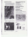
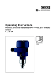
.MOPED
.
Model
~
'
~os:' '
r\
·. ~~.
*:I
·
ZDW-57008A
ZDW-57061A
ZDW-57062A
.~1
'!
!
Form No.·
61M-208B*
.,
..
·...~(
. ,
~\
'
-..~·AJ
t
[
l
I
(
\
I
,.
..
\
·.·~
/;
~~/
..-.
Two Cycle
Fuel Mixture-50:1
v
;:::;z
_ _ ,..
. . . . '\'lt'
--~- --~~~~--~-~~~-----~~
I
e.
•
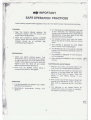
. . IMPORTANT
t.
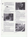
SAFE OPERATION PRACTICES
/
Local licensing, age and traffic regulatl.ons may vary from state to state. Check existing local laws.
~-
TRAINING
3. It is the absolute understanding that this unit
is not a field bike. Any licensing needed to
comply with the existing local or state vehicle
requirements In any given area is the sole
responsi bi lity of. the purchaser.
1. Read the Owner's Manual carefully. Be
thoroughly familiar with the controls and
proper use of the equipment.
2. Never allow children to operate a MOPED
without proper and close adult supervision.
Children should be of sufficient age,
understanding and capacity.
4. The operator should never place his hands,
feet or any part of his body near any moving
parts.
5. This MOPED is designed for ON E AIDER
ONLY. Carrier is not for passengers.
•
6. This MOPED should not be used in a reckless
manner, such as jumping obstacles, racing or
hill climb ing.
PREPARATION
7. This MOPED is designed for hard surfaces,
such as pavement.
1. Check fuel before starting engine. Fuel
mixture 50:1 (2112 oz. two cycle oil to 1 gallon
of regular gasoline). Do not ·fill gasoline tank
Indoors, when engine is running, or while the
engine is still hot. Wipe off any spilled
gasoline before starting the engine.
8. Never operate this MOPED on wet or slippery
surface.
MAINTENANCE AN D STORAGE
1. Keep all nuts, bolts, and screws tight to be
sure the unit is in a safe operating condition.
2. Never start this MOPED without being in
proper starting position. See page 9.
2. Never store the unit inside of a building with
gasoline in the tank where the fumes may
reach an open flame or spark. Allow the
engine to cool before storing in any
enclosure.
3. Prior to each use, the tire pressure should be
checked and maintained. Front : 25 P.S.I.,
Rear: 32 P.S.I. Maximum 36 P.S.I. front and
rear.
OPERATION
;
{'
~ I
'
y
j
..
•
f
2. Manufacturer
lights on.
recommends
running
4. The tightness of the spokes should be
checked after every few hours of operat ion.
See Spoke Adjustment on page 15 .
with
j
1 1
.,.l'\I
'~(...
1i.:
''f"
1. It is recommended the operator use a safety
helmet and eye protection.
I
··p.s
i:~.- ..
..
~
t' :-;. , •. \
;· ),.•,.'!,\,
I I..
I
~
k
'
I
\'
~'"
I
k~i. •. ''
2
ti:
-
-
------------------~.------------~~~----
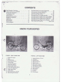
CONTENTS
Safe Operation Practices .................... 2
Index and Know Your MOPED ..... .. .... . . ... 3
Consumer Information .... . ................. 4
Tire Reserve Load ............ . ......... . ... 5
Identification .............. . ............... 6
Assembly Instructions ...................... 6
Prepare for Operation ....................... 8
Operating .... ......... ... ................. 9
Maintenance .......... .. ......... . ........ 10
Adjustments ........................ .. .... 13
Wiring Diagram ............ ..... . ...... . ... 17
Exploded VIew for Fork and Handle Bar .... ... 18
Parts List for Fork and Handle Bar ............ 19
Exploded View for Main Frame ....... .. ...... 20
Parts List for Main Frame ................ 21, 22
Exploded View for Torque Converter . . ........ 23
Exploded View and Parts List for Front Wheel 24
Exploded View and Parts List for Rear Wheel ... 25
Exploded View and Parts List for Controls .... . 26
Exploded View and Parts List for Engine .... 27-31
Parts Ordering Procedure ........... Back Cover
l
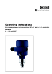
KNOW YOUR MOPED
1
,._
I
FIGURE 1. RIGHT HAND VIEW
1.
2.
3.
4.
5.
6.
7.
8.
9.
10.
11.
/ 12.
13.
14.
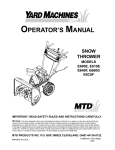
FIGURE 2. LEFT HAND VIEW
Brake/Tal I Light
Seat
Breather Cap
Fuel Tank and Cap
Choke Lever
Throttle Twist Grip
Start/Stop Switch
Brake Lever (Front)
Front Internal Drum Brake
Front Fork Extension
Right Hand Pedal
Pedal Chain
Rear Internal Drum Brake
Rear Swing Arm Shock
1. Amber Reflector (Front)
2. Headlight
3. Speedometer
4. Rear View Mirror
5. Starter Lever
6. Brake Lever (Rear)
7. Seat Adjusting Bolt
8. Red Reflector (Rear)
9. Chain Adjuster
10. Rear Wheel
11. Kickstand
12. Muffler
13. Front Wheel
3
h
- - - - --.
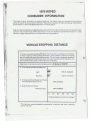
1979 MOPED
CONSUMER INFORM·ATION
0
•
This sheet contains Information on stopping distances, tire reserve loads and acceleration and passing
ability as required by the Consumer Information Regulations issued by the National Highway Traffic Safety
Administration of the United States Department of Transportation.
Data for stopping distances and passing ability were derived from tests conducted with new vehicles under
optimum road conditions by skilled test drivers and are not necessarily representative data for a used
vehicle, for mrny road conditions, or for the abilities of most operators.
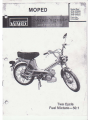
VEHICLE STOPPING DISTANCE
This figure Indicates braking performance that can be met or exceeded by the vehicles
to which it applies, without locking the wheels, under different conditions of loading
and with partial failures of the braking system. The Information presented represents
resu lts obtainable by skilled drivers under controlled road and vehicle conditions, and
the Information may not be correct under other conditions.
Description of vehicles to which this table applies: All Models of "MOPED"
············· ···· ·······M
······
A. Fully Operational Service Brake Load
28Ft.
(130 LB. Operator)
,.Ft.
Light
Maximum
B. Emergency Service Brakes (with Partial
Service Brake System Failure)
(225 LB . Operator)
NOT CA PAB LE
C. Brake Power Unit Failure
Maximum Load
NOT CAPABLE
0
100
200
300
400
500
Stopping Distance in Feet from 22 mph. •
*The maximum speed attainable by accelerating a maximum rate from a standing
start for one mile.
4
- - - - - --
0
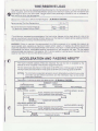
TIRE RESERVE LOAD
This table lists the tire size designations recommended by the manufacturer for use on the vehicles to
which it applies, with the recommended i nflation pressure for maximum loading and the tire reserve load
~ percentage for each of the tires listed. The tjre reserve load percentage indicated is met or exceeded by
V I each vehicle to which the table applies.
Descript ion of Vehicles to Which the Table Applies : _A
:....:..:..:.
II _M_o_;d_e_ls_
of.:...'_;'M
~
O.:...
P-=E:..::O_"_ _ __ _ _ _ _ _ __
2-1/4-17
Recommended Tire Size Designations
Front
Rear
Recommended.Cold Inflation Pressure
for Maximum Loaded Vehicle Weight
1
•
25 PSI
32 PSI
*The difference, expressed as a percentage of tire load rating, between (a) the load rating of a tire at the
vehicle manufacturer's recommended inflation pressure at the maximum loaded vehicle weight and (b) the .
load imposed upon the tire by the vehicle at that condition .
WARNING . Failure to maintain the recommended tire inflation pressure or to increase tire pressure as
recommended when operating at maximum loaded vehicle weight, or loading the vehicle beyond the
capacities specified on the tire placard affixed to the vehicle, may result in unsafe operating conditions due
to premature tire failure, unfavorable handling characteristics, and excessive tire wear. The tire reserve
load percentage is a measure of tire capacity, not of vehicle capacity. Loading beyond the specified vehicle
capacity may result In failure of the vehicle components.
ACCELERATION AND PASSING ABILITY
This figure indicates passing times and distances that can be met or exceeded by the
vehicles to which it applies in the situation diagrammed below.
'
The low speed pass assumes an initial speed of 20 MPH and a limiting speed of 35 MPH.
The high speed pass assumes an initial speed of 50 MPH and a limiting speed of 80 MPH.
NOTICl: The information presented represents results obtainable by skilled drivers under
. controlled road and vehicle conditions and the information may not be correct
·;; under other conditions.
l
Descripllon of vehicles to which this table applies: All Models of " MOPED"
LOWfSPEED PASS
HIGJ-tSPEED PASS
LOW SPEED
INITIAL SPEED: 20 MPH
I
SUMMA RY TAB LE:
46 SECONDS
FEET
SECONDS
1,500 FEET
NOT CAPABLE
LIMITING SPEED: 35 MPH
TOTAL PASSING DISTANCE FEET
TOTA L PASSING TIME SECONDS
············ · ················ · ··············· - ~
1 40o
I
-·~ 1+ 40+1
•• • ••••••••• •• •• •• •••••• •
55 TRUCK
CONSTANT 20 MPH
HIGH SPEED (MOPED NOT CAPABLE)
INITIAL SPEED : 50 MPH
LIMITING SPEED: 80 MPH
TOTAL PASSING DISTANCE FEET
~
l
TOTAL PASSING TIME SECONDS
I
····························· · ······ · · ······· · · · ······ · ······~
~ 100~c::::J··· ···· ······ · ···· ·· ········-~~~100~
55 TRUCK
CONSTANT 50 MPH
5
I
TOOLS REQUIRED FOR
ASSEMBLY
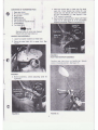
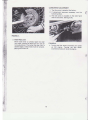
IDENTIFICATION
1. The identification number will be on the vehicle model number plate (See figure 3.) located
on the main frame under the handle bars. The
identification number is also stamped into the
frame on the left side, just under the rear fork
assembly.
One 7/16" Open end or box end wrench.
One 12" Adjustable wrench.
One 6" Adjustable wrench.
One 1f4" Standard flat screwdriver.
OTHER MATERIALS
REQUIRED
One can of two-cycle oil and gasoline.
ASSEMBLY
INSTRUCTIONS
The MOPED comes completely assembled w ith
the exception of the handle bar, rear view mirror,
and pedals. See figures 5 and 6.
Reference to right and left hand side are from the
normal riding position , faci ng forward .
FIGURE 3.
I
2. The Engine Type Number and Letter is
stamped into the metal on the crankcase. See
figure 4.
~~. l~r
~
FIGURE 5.
\
t
1
r r\
~· l'
4--..- ( '
! •'
i
FIGURE 4. .
'2J1 ~ ~ ~ 1167 ~
FIGURES.
6
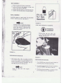
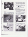
4. Place the handle bar In place over the steel
balls (8). Place handle bar plate (5) over
handle bar and secure with four hex screws
(6) and lockwashers (7). See figure 8. One
7/16" wrench is required.
5. Secure-handle bar plate (5) in place with head
tube nut (4). See figure 9. A 12" adjustable
wrench is required. Press In plug button (3).
CONTENTSOFHARDWAREPACK
1.
2.
3.
4.
5.
6.
7.
8.
Rear view mirror
R.H. and L.H . pedals
Plug button
Head tube nut
Handle bar plate
Hex screws for handle mount
Lockwashers
Two steel balls
.NOTE
Remove block of wood and discard.
Retain bolt and head tube nut.
HANDLE BAR ASSEMBLY
1. Leave two spacer washers on head tube.
2. Place the steel balls (8) in upper fork. See
figure 7.
FIGURE 9.
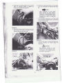
REAR VIEW MIRROR ASSEMBLY
Posit ion rear view mirror on handle bar. Secure
clamp in desired position. See figure 10.
FIGURE 7.
3. Before assembly , check adjusting cone for
tightness.
1
FIGURE 10.
FIGURE 8.
7
SEAT ASSEMBLY
1. Place the seat post clamp on seat post.
2. Line up the two rear clamps on seat with
holes In rear frame of MOPED.
3. Tighten the pillar clamp nut and bolt securely.
4. Tighten the rear seat clamp nuts and screws.
PEDAL ASSEMBLY
I
!
Assemble pedals to crank using an adjustable
wrench. Tighten securely. See figure 11.
I
I
~NOTE
2V2 oz. Oil
To 1 Gal.
Gasoline
FIGURE 12.
Threaded ends of pedals are marked
"R" and "L" for right and left hand
sides. See figure 11. Right and left
hand side Is determined from the
operator's position.
FUEL TANK CAPACITY 23,4 QUARTS.
Remove gas cap and open vent
to fill. You must close vent before
starting. See figure 13.
FIGURE11 :
PREPARE FOR OPERATION
FIGURE 13.
1. Fuel mixture 50:1. Mix in a clean container
2112 ounces of SAE 30 or snowmobile oil or 2
cycle oil per gallon of regular gasoline. This
mixture assures positive lubrication. Do not
use 10W-30 type oils. See figure 12.
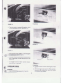
FREE-WHEELING FEATURE
1. Your MOPED has a shut-off block located on
the drive pulley, left hand side of bike.
~NOTE
2. You must engage the shut-off block in order to
start your MOPED. See figure 14 and 15.
Never fill fuel tank with engine
running.
3. The drive pulley is marked (+)positive, which
is the engaged position. See figure 14.
8
~I
FIGURE 16.
=IGURE 14.
4. The drive pulley is marked (0) negative, which
is the disengaged position. See figure 15.
FIGURE 17.
IGURE 15.
6. The shut-off block positioned in the (0) allows
you to free-wheel or pedal the 'bike with the
engine off.
Shown "Reserve"
7. To change the shut-off block position simply
turn to (0) or ( + ) by hand.
FIGURE 18.
OPERATING
oc;-·
2. Engage the shut-off block. See figures 14 and
15.
3. Turn the engine stop switch to RUN position.
See figure 19. Engine stop switch is located
on the right hand handle.
STARTING
Open fuel valve.)ee figures 16, 17 and 18.
9
PUTTING MOPED IN MOTION
Accelerate slowly after the engine has begun to
run. The torque converter engages as the
revolution increases and the bike moves off. It Is
recommended to use the pedals for help when on
inclines.
STOPPING THE BIKE
I
l
The MOPED is stopped by closing the throttle
control and applying the hand brake levers located
on the handle bars. The front wheel brake lever Is
located on the right hand side. See figure 19. The
rear wheel brake lever Is located on the left hand
side. See figure 20.
~CAUTION
Braking procedure-Use rear wheel
brake for stopping by actuating the
left hand brake lever. To assist In
stopping, the right hand brake lever
is to be applied AFTER actuating the
left hand brake lever. If In an emergency stop situation the operator
applies front brake only it can cause
loss of control of the MOPED.
STOPPING THE ENGINE
Shut off engine with engine stop switch, located
on right hand handle bar. See figure 19. Do not
shut off engine by applying the starter control
lever. ALWAYS SHUT OFF FU EL VALVE
OPERATION OF LIGHTS AND HORN
Push light switch which is located on the left
handle bar i n either direction to turn on head and
taillights. Middle position is the off position. See
f igure 20.
To operate horn, push the button on the side of
the control switch located on the left handle bar.
See figure 20.
FIGURE 20.
If the engine choke control lever is pulled too long
so that the engine will not start , shut fuel valve
and try to start engine several times without
applying the choke control. If necessary, remove,
dry and reinstall the spark plug- then repeat
starting procedure .
MAINTENANCE
AIR CLEANER
1. Remove the left hand step plate, by removing
two screws and two belleville washers. A 3/ 8"
wrench is required .
~CAUTION
Avoid unnecessary acceleration of
engine when not in motion, otherwise clutch will engage.
2. Loosen (do not remove) band clamp at the
carburetor with a flat screw driver. See figure
21.
10
4. Check the clear breather tube to be sure It Is
free of any dirt. Breather tube can be cleaned
with air pressure. Blow dirt from housing thru
housing, out of tube. See figure 23.
5. When reinstalling air cleaner be sure breather
tube is pointed upward and clears the wiring .
•
. . NOTE
The air cleaner should be cleaned
every 600 miles.
BELT REPLACEMENT
The belt is self-tensioning at all times. No belt
adjustment is necessary.
1. Remove the left hand step plate from MOPED.
Remove two screws and belleville washers. A
3/8" wrench is required.
2. Remove the muffler by removing two hex nuts
at the muffler flange to cylinder head of
engine. A 9mm socket wrench is required.
Remove two allen head screws from bottom
of muffler. See figure 24.
FIGURE 21.
3. Slip the air cleaner and band clamp off of the
carburetor. Pull the fiber element out of
housing and wash in gasoline, dry and
lubricate with a 1/2 teaspoon of light oil. See
figure 22.
FIGURE24.
FIGURE 22.
3. Pop off the left hand engine side cover with a
screw driver. See figure 25.
Screwdl·~fvAr
Clear
- - B,..ther Tube
'l
FIGURE 23.
FIGURE 25.
11
•
4. Disconnect the starter cable from the starter
lever, by pressing Inward to release the
tension on the cable. See figure 26.
6. Remove two belt guard bolts at drive pulley
Two 1/2" wrenches are required. See flgun
28 .
. . NOTE
Upon reassembly of belt guard
bolts, be sure you have approximately 1/8" clearance between bolts
and the belt. You may have to bend
the bolts up or down to make this
adjustment.
7. Pull the starter cable back out of way. With
one hand push the engine down, and remove
the belt. See figure 29.
FIGURE 26.
5. Remove the starter lever by removing two hex
head screws from bottom of engine. A 5/16"
wrench Is required. See figure 27.
FIGURE 29.
8. Place new belt back on drive pulley and torque
converter. Reverse the above steps for
reassembly.
&cAUTION
The extension springs on your
MOPED are under pressure. Exercise caution if you remove them for
any reason . See figure 30.
FIGURE 27.
~·
FIGURE 28.
FIGURE 30.
12
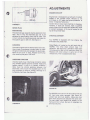
ADJUSTMENTS
(A)
ENGINE COOLANT
Engine heat is dissipated by an amount of coolant
sealed in the cylinder block. M lxture is 1/ 3
anti-freeze to 2/3 water and gives protect ion to
about -13 degrees Fahrenheit.
Coolant should never need checking or changing.
However, if leaks are noticed, have a qualified
person determine the cause and replace any parts
or coolant necessary. A fill plug Is located on the
top of the cylinder head.
FIGURE 31.
SPARK PLUG
Electrode Gap
r.
The electrode gap expands during operation from
heat. This Is why the electrode gap has to be
adjusted to specification from time to time. This
in turn is done by bending ground electrode (A).
The specific gap is .020 inch. See figure 31.
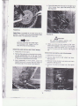
CHAIN ADJUSTMENT
Your MOPED is equipped with two chains, the
drive chain and pedal chain.
I
I
CLEANING
Drive Chain - Is located on the left hand side of
MOPED. The drive chain should have 1/ 2"
deflection. See figure 33. Lubricate at least every
100 miles with a light oil for maximum chain life.
Replace with chain shown in parts list of this
manual only. This is a special chain size.
The spark plug.should be cleaned every 600 miles.
Use a piece of sandpaper or emery board to clean
the ground electrode and between the electrodes.
Blow out any dust or sand . Replace spark plug
after resetting the gap to .020 inch.
CHECKING FUNCTION
Unscrew spark plug, install plug connector, place
plug threads against ground (cylinder head) and
operate starter. If plug is in perfect condition, :
there must be strong sparking between the
electrodes. Only touch the insulated part of the
plug connector to avoid a "shock" although it is
completely harmless. See figure 32.
FIGU RE 33.
The MOPED must rest on the kick stand with the
left hand step plate removed. See figure 34.
Loosen rear axle nuts slightly. Make sure that
both chain adjusters are adjusted the same rate.
The rear wheel must always be parallel to the
frame and front wheel. Be sure to retighten the
axle nuts securely.
FIGURE 32.
13
4. Place the brake and hub back in the right hand
side of wheel. Next, place the spacer on axle.
See figure 36.
FIGURE 34.
Pedal Chain-Is located on the right hand side of
MOPED. The pedal chain has an automatic chain
adjuster (Idler). No adjustment is required.
FIGUR E 36.
~CAUTION
Be sure to replace spacers and
washers in proper positions.
.,_.NOTE
J3oth the drive chain and pedal chain
are equipped with master link for
easy removal and maintenance.
5. Make sure that the fork holder on the right
hand side engages in the slot of front wheel
hub lever. Place flat washer next to fork and
secure the axle with hex locknut. See figure
36.
REMOVING AND INSTALLING FRONT WHEEL
1
1. Place bike on kick stand.
REMOVING AND INSTALLING REAR WHEEL
2. Remove the axle and nut from the front wheel.
Lift the speedometer out of the way if your
MOPED is so equipped. Lift the brake hub out
of the way and remove the front wheel.
3. Upon reassembly of front wheel, place the
speedometer arm in one of the two holes on
left hand side of front wheel. See figure 35.
1. Place bike on kick stand.
2. Remove black bolt at rear wheel hub lever.
See figure 37.
3. Remove the hex locknut, axle bolts and chain
adjusters. See figure 37.
4. Remove the chain and brake hub. See figure
37.
'
FIGURE 35.
FIGURE 37.
14
I
5. Upon reassembly eof rear wheel place the
spacers between the wheel and fork.
6. Replace the chain, brake hub, axle bolt, hex
locknut, chain adjusters and tighten by hand.
Be sure slot in rear wheel hub lines up with
hole in frame and replace the black bolt. See
figure 37 .
. . NOTE
Be sure to insert axle bolt from left
side of bike.
7. To readjust the chain, see chain adjustment
on page 13 of this manual.
t
FIGURE 39.
SPEEDOMETER (OPTIONAL)
The speedometer drive on the left front wheel hub
has a lubrication nipple. Always lubricate here
every 600 to 900 miles. See figure 38.
SPOKE ADJUSTMENT
1. The tightness of spokes should be made every
few hours of operation.
2. To check for correct spoke tension, wiggle
each spoke gently. If the spoke nipple at the
rim is able to move, the spoke is too !oose.
3. Another way to check spoke tension is by
gently tapping a metal object, such" as a
screwdriver, against each spoke. If the spokes
are equally tightened, they will produce the
same sound or pitch.
CD)
4. To tighten a spoke use a spoke wrench or an
adjustable wrench.
BRAKE ADJUSTMENT
1. A 10 mm wrench is required.
2. Loosen jam nut on brake cable and turn the
barrel nut on brake cable counterclockwise for
more adjustment and clockwise for less
adjustment. See figures 40 and 41.
FIGURE 38.
CLEANING FUEL VALVE
It is recommended to remove and clean the fuel
valve thoroughly once each year. Clean with
gasoline by moving the lever through all of its
positions. Cleanliness is especially important for
filter screen. Flushing with clean gasoline is just
as important as blowing through with the air
pump.
Don't forget to insert the fuel tank connection
seals correctly when reinstalling.
HEADLIGHT AND TAIL LIGHT
~I
The headlight is always at low; it has a 6V-18W
sealed beam which is replaceable.
The taillight has a 6V-5W bulb and the brake light
has a 6V-10W bulb, which can be replaced by
removing two screws and taillight lens. See figure
39.
FIGURE 40.
15 .
CARBURETOR ADJUSTMENT
1. The idle screw is preset at the factory.
2. If adjustment becomes necessary use the
following steps.
3. The idle screw is located on the right hand
side of carburetor. See figure 42.
FIGURE 41.
3. Brake Wear limit
When brake lever on wheels reach the wear
limit mark, remove the lever and turn over for
more adjustment. Then when the wear limit is
reached again, brake shoes must be replaced.
.see figures 40 and 41.
FIGURE 42.
4. Turning the idle screw clockwise will speed
up the engine. Turning the idle screw
counterclockwise will slow the engine.
16
~
~·;
f,
I
\
•
1
Black
Engine
t
' f.
A = Green-Black
B = Green
C = Gray
D = Yellow
E = Blue
Blue
Black
3
Blue
Coil
i-
Attach at
Coil or Terminal
Block Mounting
Yellow
Red
t
~
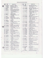
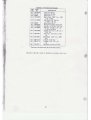
PARTS LIST FOR ELECTRICAL SYSTEM
REF.
NO.
1
2
3
4
5
6
PART
NO.
725-0637
725-0598
725-0599
725-0539
725-0600
725-0592
725-0591
7
8
9
725:0541
725-0533
725-0538
DESCRIPTION
Wire Harness-Comp.
Terminal Block Ass'y.
Kill Button Switch
Horn
Accessory Switch
Headlamp Ass'y. for
Speedometer (Optional )
Headlamp Ass'y. w/ o
Speedometer (Optional)
Electric Wire (2 Req'd.)
Tail lamp Ass'y.
Brake Light Switqh (2 Aeq'd.)
1/
ZDW-57008A .
ZDW-57061A
ZDW-57062A
I
I.
r
I
~
r
I\
~
'
32
31
'
~I
1
77
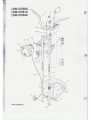
FORK ASSEMBLY
18
...
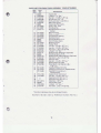
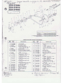
PARTS LIST FOR FRONT FOR K ASSEM BLY COMPLETE #06894
REF.
NO.
PART
DESCRIPTION
NO.
1 06895
2 736-0329
3 710-0747
4 726-0186
5 712-0304
6 745-0167
7 06891
9 741 -0285
10 741-0287
11 730-0114
12
13
14
15
J6
741 -0284
741 -0283
732-0340
731-0400
06827
17 06838
18 731-0400
19 731 -0401
20 710-0289
21 710-0258
22 712-0107
23 736-0329
24 745-0171
25 06828
26 745-0170
27 712-0107
28 725-0539
29 710-0289
30 725-0590
31 710-0725
32
34
731-0426
731-0424
731 -0468
35
36
37
38
39
40
41
42
745-0169
710-0258
-
741-0219
06858
736-0329
712-0107
Handle Bar
L-Wash.1/4" Scr. •
Hex Scr. 1/4-28 x 1.25" Lg.
Plug Button .81" 1.0.
Fork Lock Nut 1.0-24 N.S.I.
Rear View Mirror
Telescope Fork Ass'y.
Cone- Adj. Fork
Fork Bearing
Side Reflector 2.0" Dia.
Amber
Ball Fork Cup
Cone- Lower
Compression Spring
Bushing Nylon
Fork Extension-L.H.
Front Fender Ass'y.
Bushing Nylon
Rubber Boot
Hex Scr. 1/4-20 x .50" Lg. •
Hex Scr. 1/4-20 x .62" Lg. •
Hex Cent. L-Nut 1/4-20 Thd.
L-Wash. 1/4" Scr. •
Speedometer Gear Box (Optional)
Fork Extension-R.H.
Speedometer Cable 650mm (Optional)
Hex Cent. L-Nut 1/4-20 Thd.
Horn 6V-18W
Hex Scr. 1/4-20 x .50" Lg. •
Sealed Beam 6V-18W
Truss Mach. AB Tap Scr. #8 x
1.00" Lg. *
Headlight Bezel Chrome
Headlight Housing for Speedometer
Headlight Housing wlo
Speedometer
Speedometer (Optional)
Hex Scr. 1 / 4-20 x .62" Lg. •
Supplied with Ref. No. 11
Supplied with Ref. No. 11
Steel Ball .125" Dia.
Handle Bar Plate
L-Wash. 1I 4" Scr. •
Hex Cent. L-Nut 1 I 4-20 Thd .
*Common Hardware may be purchased locally.
Important: Do not order by Reference Number (Ref. No.).
/
19
'I
I
ZDW-57008A
ZDW-57061A
ZDW-57062A
1I
I' .I :
,I
MAIN FRAME
20
PARTS LIST FOR MAIN FRAME
REF.
NO.
PART
NO.
1
2
3
4
5
6
757-0293
757-0294
757-0287
710-0289
06840
710-0289
06910
732-0368
7
731 -0400
8
9
10
731 -0474
06922
710-0403
11
12
13
14
06843
731-0307
712-0107
736-0175'
15
16
17
12894
725-0533
710-0207
18
19
745-0176
736-0175
20
21
22
712-0107
710-0672
736-0105
23
750-0445
24
25
26
27
28
29
30
731-0475
745-0175
710-2205
06847
712-0296
06831
736-0175
31
32
33
712-0107
712-0107
736-0175
34
713-0122
35
713-0247
36
37
38
39
736-0119
712-0267
710-0378
732-0157
40
41
42
710-0180
710-0117
712-0306
43
44
714-0507
736-0185
45
756-0194
DESCRIPTION
Seat Ass'y. - Biack
Seat Ass'y. - Burgundy
Bench Seat Ass'y.
Hex Scr. 1/4-20 x .50" Lg. •
Carrier
Hex Scr. 1/4-20 x .50" Lg. •
Shock Absorber Cover Ass'y.
Compression Spring .88"
O.D. X 5.65" Lg.
Telescopic Bushing 1.10"
O.D.
Telescope Boot
Telescope Tube
Binder Bolt 5/16-24 x 1.75"
Lg. Spec.
Rear Fender
Snap Bushing
Hex Cent. L-Nut 1/4-20 Thd.
L-Wash .. 270" I. D. x .51" O.D.
X .030
Cable Clip
'
Taillight
Hex Mach. Tapp Scr. 1/4-20 x
1.00" Lg. *
ttcense Plate Bracket
L-Wash .. 270" I. D. x .51" O.D.
X .030
Hex Cent. L-Nut 1/4-20 Thd.
Hex Scr. 3/8-24 x 1.25" Lg.
Beii.-Wash .. 400 I. D. x .88
O.D. X .060
Split Tubing Spacer .395 x .50
X .50
Grommet
Shock Absorber Ass'y.
Hex Scr. M12 x 1.5 x 170
Chain Adjuster
Hex Cent. L-Nut 3/8-24 Thd.
Rear Fork Ass'y.
L-Wash . .270" I. D. x .51" O.D.
x.030
Hex Cent. L-Nut 1/4-20 Thd.
Hex Cent. L-Nut 1/4-20 Thd .
L-Wash .. 270" I.D. x .51" O.D.
X .030
#48 Master Link 1/2" Pitch
Type II
Freewheel-Sprocket 18
Teeth
L-Wash. 5/16" Scr. *
Hex Nut 5/16-18 Thd. •
Hex Scr. 5/16-18 x 2.50" Lg. •
Extension Spring .50 0. D. x
3.25" Lg.
Hex Scr. 3/8-24 x .75" Lg. •
Hex Scr. 3/8-24 x 1.00" Lg.
Hex Top L-Jam Nut 3/8-24
Thd.
Cotter Pin 3/32 x .75" Lg.
FI-Wash .. 406" J.D. x .74"
O.D. X .063
Idler Pulley 1.50 0.0. x .378
I. D.
.
REF.
NO.
PART
NO.
46
47
06896
736-0105
48
49
50
712-0296
712-0158
741 -0249
51
52
710-0378
750-0347
53
741-0249
54
736-0187
55
56
57
738-0419
710-0758
736-0309
58
736-0290
59
724-0156
60
61
62
751-0214
751-0237
717-0389
63
64
65
66
754-0235
736-0119
712-0267
732-0433
67
68
69
70
71
72
73
74
75
76
06835
736-0119
752-0691
751-0251
736-0329
712-0107
712-0296
736-0105
738-0141
732-0362
77
78
06878
738-0420
79
80
81
82
710-0620
06861
712-0107
745-0165
83
84
745-0174
751-0249
85 713-0241
86 • 751-0115
87
88
89
723-0348
751-0248
06863
06862
06906
90 . 712-0213
21
DESCRIPTION
Chain Idler Brkt. Ass'y.
Beii.-Wash .. 400 I. D. x .88
O.D. X .060
Hex L-Nut 3/8-24 Thd.
Hex Cent. L-Nut 5/16-18 Thd.
Flange Brg .. 630" O. D.Plastic
Hex Scr. 5/16-18 x 2.50" Lg. *
Rear Fork Spacer .62" O.D. x
.38 I. D. x 2.8
Flange Brg .. 630" O.D.Plastic
FI-Wash .. 640" I. D. x 1.25"
O.D. X .060 Hdn.
Pedal Shaft
Socket Hd. 3/8-24 x 4.00" Lg. *
FI-Wash .. 71" I. D. x 1.17"
0. D. x .036 Spec.
FI-Wash .. 640" I. D. x 1 .00"
O.D. X .067 Hdn.
Pedal (Set of Two) R.H.
and L.H.
Pedal Crank Cotter
Pedal Crank- L.H.
7.5" Dia. Pulley with 11 Tooth
Sprocket
V-Belt 1/2" X 35" Lg.
L-Wash. 5/16" Scr. •
Hex Nut 5/16-18 Thd. •
Extension Spring .50" O.D. x
2.75" Lg.
Kickstand Ass'y.
L-Wash. 5/16" Scr.*
Solo Engine
Rubber Engine Bushing
L-Wash. 1/4" Scr. •
Hex Cent. L-Nut 1 / 4-20 Thd.
Hex Cent. L-Nut 3 / 8-24 Thd.
Bell-Wash. 3/8" I.D.
Shld. Scr . .437" Dia. x .350
Extension Spring .75" 0. D. x
8.00" Lg.
Engine Brkt.
Shld. Scr .. 312" Dia. x 4.03"
Lg.
Hex Scr. 3/8-24 x 4.50" Lg. •
Cable Cover
Hex Cent . L-N ut 1/4-20 Thd.
Steering Lock with Keys
(Optional}
Gas Cap Ass'y.
Pedal Crank wI Sprocket
30 Teeth
#48 Chain 1 / '2." Pitch x 87 Link
Gas Line .18"1.D. x .31" O.D.
x13
Hose Clamp
Gas Valve M12 ~ 1
Frame Ass'y.
Frame Ass'y. w/o Shocks or
Fork Lock
Frame Ass'y. w/o Fork Lock
Binder Nut 5/16-24 Thd.
·'
PARTS LIST FOR MAIN FRAME
REF.
NO.
91
92
93
94
751-0252
30102
06877
736-0270
95
710-0653
96
97
98
99
06876
749-0310
710-0376
710-0597
100
750-0348
I
101
738-0421
r II .
102
736-0264
103
104
736-0119
736-0175
105
712-0107
r
I
I
f.
J •
l
I
I
I
t
~
I
PART
NO.
I
.,'
~
r
DESCRIPTION
Tank Vent Block
Seat Post .81 Dia.
Step Plate-L.H.
Beii.-Wash .. 265" I.D. x .750"
O.D. x.062
Hex Wash. SF-Tap Scr.
1 / 4-20 X .38" Lg.
Step Plate-R. H.
Swing Arm Brace {Optional)
Hex Scr. 5 / 16-18 x 1.00" Lg. •
Hex Scr. 1 / 4-20 x 1.00" Lg. •
(Inside Tai llight)
Spacer .62" O.D. x .38" I. D. x
3.84" Lg.
Shld. Scr .. 312" Dia. x 2.45"
Lg.
Bell-Wash .. 330" I. D. x .630"
O.D.
L-Wash. 5/16" Scr. •
L-Wash .. 270" I. D. x .51 "
I. D.
Hex Cent. L-Nut 1 / 4" Thd.
*Common Hardware may be purchased locally.
f
Important: Do not order by Reference Number (Ref. No .).
·,
22
j~~~ftf(),-.
fo#lt>J~
ltv
_,., ol'ti.:i>
ncrtt>I\J
d~Cc.Ll ~1-~ ~--']t'dj~tt4- .U~ ~~
~
I 0
ZDW-57008A
~ ZDW-57061 A
"'Y ZDW-57062A
1/
22
JO
28
.....
>_..-'\:"
717-0411
717-0410
/17-0409
Torque Converter 20 M.P.H.
Torque Converter 25 M.P.H.
Torque Converter 30 M.P.H.
PARTS LIST FOR TORQUE CONVERTER
REF .
NO.
1
2
3
I
~
PART
NO.
REF.
NO.
DESCRIPTION
712-0302
732-0367 '
06879 732-0349
" U"-NLJt M5
Spring Wire Clip
ClutclfOi.s Ass'y.
4 ~·
·compression Spring 1.18
0.0. x.901.0. x.83
"
5 ..06881
Spring Plate,
~ 748-0265;· ''; ,Torque Converter-Weight
r 732-0348
Extension Spring .34" 0.0. x
Lg.
8 06885
Pulley-Hub Ass'y.
9 741-0224
Needle Brg. 1.125" I. D. x
1.38" 0.0. X .37
10 748-0268
Flange Bushing (For 20m.p.h.)
'
748-0267
Flange Bushing (For 25m.p.h.)
748-0266
Flange Bushing (For 30
m.P.h.)
11 732-0350
Telescope Spring 1.38" 0.0.
X .94 1.0. X 1.00" Lg.
12 748-0262
Pulley Half Ass'y.
13 731-0472
Shut-off Block
14 712-2203
Hex Ins. L-Nut M4
15 732-0365
Leaf Spring Ass'y.
16 710-2202
Hex Scr. M4 x 12
I
17 SL-0054219
Seal
18 735-0194
Rubber Sleeve
?J,wll (Jo;J})
/t~
DESCRIPTION
19
713-0248
20
736-0290
21
710-2203
22
23
24
25
732-0364
756-0321
712-2203
741-0282
26
27
SL-005421£
736-0309
28
736-0187
29
30
754-0235
715-0142
·31
32
33
34
35
36
23
PART
NO.
...
736-0308
712-2200
736-0931
736-0722
710-2200
751-0250
-
Sprocket Hub 11 -Teeth x .50"
Pitch
FI-Wash .. 640 1.0. x 1.00"
0.0. x .067 Hdn.
Oval Counter Sunk Scr. M4 x
20
Spring Plate
7.5" Oia. Pulley
Hex Ins. L-Nut M4
Needle Brg. 161.0. x 22 0 . 0 .
x14
Seal
FI-Wash . .71" I. D. x 1.17"
0. D. x .036 Spec.
FI-Wash .. 640" 1.0. x 1.00"
0.0. X .06 Hdn.
" V" -Belt 1/2".x 35" Lg.
Spring Pin Roll1/8" Oia. x
.50" Lg.
Beii.-Wash .. 430" 1.0. x .90"
0.0. X .030
Hex Jam Nut M10 x 1
FI-Wash .. 203 1. 0. x .41 0.0.
X .040
L-Wash. #10
HexScr. M5x18
Clutch Spring Lever
I Jl
,I
ZDW-57008A
ZDW-57061A
ZDW-57062A
I
I
''
L
I
'
I
l,/;)k;
,
J
2
I
10
PARTS LIST FOR FRONT WHEEL ASSEM BLY COMPLETE 734-0950
REF.
PART
N O.
NO.
1
734-0952
2
3
4
5
6
7
8
9
10
11
12
734-0774
734-0775
734-0776
734-0955
755-0220
755-0183
732-0361
711-0692
06917
712-2003
736-0192
13
14
16
17
18
710-2204
736-0329
746-0344
06912
750-0436
19
20
761-0173
741-0290
21
750-0429
22
23
24
25
734-0958
745-0171
712-2204
750-0277
DESCRIPTION
Front Wheel Ass'y. Less Tire
and Tube
Tire Only 21.0 x 2.25
Inner Tube Only 21 .0 x 2.25
Rim Band
Rim Only 1.35 x 17
Spoke 105 Dia. x 7.28" Lg.
Spoke Nipple
Extension Spring
Brake Cam
Brake Lever
Hex Nut M6
FI-Wash .. 531 I. D. x .93 O.D.
x.090
Hex Scr. M12 x 1.5 X 150
L-Wash. 1/4" Scr.
Brake Cable 38:9" Lg.
Brake Arm Ass'y.- Front
Spacer .480 I. D. x .81 O.D. x
.626 Lg.
Brake Shoe Comp . 105mm
Ball Bearing 12 I. D. x 28 0. D.
x8
Spacer .505 I. D. x .-63 0. D. x
2.385 Lg.
105mm Front'Cast Hub Ass'y.
Speedometer Gear Box (Optional)
Hex Jam Ins. L-Nut
Spacer
24
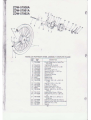
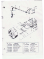
PARTS LIST FOR REAR WH EEL ASSEM BLY COM PLETE 734-0951
3
(j)
REF.
NO.
PART
NO.
1
734-0953
2
3
4
5
6
7
8
9
10
734-0774
734-0~
734-0 76
734-0955
755-0220
755-0183
710-2205
06847
750-0277
11
741-0290
12
750-0430
13
14
15
16
17
19
20
21
23
24
25
2S
27
734-0959
713-0246
06921
710-2201
732-0361
761-0173
711 -0692
06913
06917
736-0329
712-2003
712-2204
746-0345
750-0436
28
29
713-0252
713-0242
Hl
G)
DESCRIPTI ON
Rear Wheel Ass'y. Less Tire
and Tube
Tire Only 21 .0 x 2.25
Inner Tube 21 .0 x 2.25
Rim Band
Rim Only 1.35 x 17
Spoke 105 Oia. x 7.28" Lg.
Spoke Nipple 1 05 Oia.
Hex Scr. M12 X 1 .5 x 170
Chain Adjuster
Spacer .510 1.0. x .68.0.0. x
.44" Lg.
Ball Bearing 121.0. x 28 0.0.
x8
Spacer .5051.0. x .63 0.0. x
3.173" Lg.
105 Oia. Rear Cast Hub Ass'y.
Sprocket 57 Teet h .50 Pitch
Screw Lock Strip
Hex Self-Tap Scr. M6 x 20
Extension Spring
Brake Shoe Comp. 105mm
Brake Cam
Brake Arm Ass'y.-Rear
Brake Lever
L-Wash. 1/4" Scr.
Hex Nut M6
Hex Jam Ins. L-Nut
Brake Cable 64<.8"•Lg .
Spacer .480 1.0. x .81 0.0. x
.626" Lg.
#415,S Master Link
#415 S Chain .50 Pitch
97 tinks
25
/psfJPt
·fit~ rd-kr?'
~'
CiJ&j<';&
t;/1- 57tf-t.IY I~
~ft' - ?a~~ "7
/) VU!c~
f1) 4e,
am <--1:41f '
5
3
6
7
ZDW-57008A
ZDW-57061A
ZDW-57062A
8
9
_i
15-
-
---1
Jl.,----11
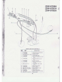
PARTS LIST FOR CONTROLS
REF.
PART
NO.
NO.
1
2
3
4
5
746-0284
746-0286
MA-270.51 -03.1 SZ
746-0349
746-0347
6
746-0348
7
8
746-0286
746-0285
9
MA-HL3-11 -1
10
11
12
13
14
15
16
746-0345
746-0288
MA-13.1-Z3.2SZ
MA-21 0.1-03. ?TP
746-0344
746-0346
MA-270.1 -03. 7TP
DESCRIPTION
Throttle Control Comp.
Nipple Holder
Choke Lever
Inner Cable 425
Throttle Cable 42 x 3.18"
Ext.
Choke Cable 42 x 2.0"
Ext.
Nippier Holder
Brake Lever Control
Comp.
Truss Mach. Scr. M6
x15
Brake Cable 64.8
Dummy Grip
Cort;~pression Lever
Brake Lever
Brake Cable 38.9
Starter Cable 37-5.5 Ext.
Brake Lever
26
~
11
26
--6#
1
~
6
8
32
2
~
1
33
17
3
5 -- - -- -----..
15 --~0!;;
~
\---21
9
u----22
~23
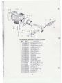
PARTS LIST FOR ENGINE CRANKCASE
IT
REP:'
NO.
PART
NO.
1
SL-2011570
SL-2011572
SL-0042208
SL-001 0161
SL-0020102
SL-0054203
SL-0066217
SL-0062112
SL-2061334
SL-0034107
SL-0020169
SL-2045460
SL-2045455
SL-0015158
SL-0034103
SL-00201 01
SL-0031292
SL-2012448
SL-2061284
SL-2074525
SL-2042289
SL-2063163
SL-0015226
SL-0054128
2
3
4
5
6
7
8
9
11
15
17
21
22
23
26
27
28
29
30
31
32
33
DESCRIPTION
Crankcase- R.H.
Crankcase-L.H.
Crankcase Pin
F. H. Screw M6 x 50
Hex Nut M6
Cran kshaft Seal 26 x 35 x 7
Ignition Cable Grommet
" 0 " -Ring
Crankcase Gasket
Spring Washer 86
Hex Nut M6
Cover- Clutch
Cover-Ignition
Stud Screw M5 x 15
Spring Washer 85
Hex Nut M5
Washer
Carburetor Flange
Carburetor Flange Gasket
Reed Valve Housing_
Reed Valve
Positioner
Stud Screw
Crankshaft Seal15 x 35 x 7
27
I
19
31
20
18
15
16
-
17
14
©
13
25
27
~
28
2
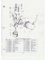
PARTS LIST FOR CRANKSHAFT-PISTON-CYLINDER
NO.
PART
NO.
1
2
3
SL-0050102
SL- 2200674
SL-0031375
6
8
9
10
11
12
13
14
15
16
18
19
20
21
24
SL-00151'01
SL-0030144
SL-0020161
SL-0034115
SL-2200593
SL-2048227
SL-2031238
SL-0055144
SL-0015201
SL-0030100
SL-0028100
SL-2200684
SL-2000685
SL-2061337
SL-2061346
736-0308
25
26
27
28
29
30
31
32
712-2200
SL-0052186
SL-0061255
SL-0010266
SL-0062159
SL-0055106
SL-0016126
SL-0061 210
1
REF.
17
DESCRIPTION
Ball Bearing 15 x 35 x 11
Crankshaft
Spacing Washer 15.3 x 22
x0.5
Woodruff Key 3 x 3.7
Washer8.4
Hex Nut M8LH Thd.
Crown Washer 8
Piston Complete
Piston Ring
Piston Pin 10 x 6 x 32
CirclipA10
Stud Screw
Washer6.4
Hex Nut M6 Thermae
Cylinder Comp.
Cylinder Head
Cylinder Head Gasket
Cylinder Foot Gasket
Beii. -Wash .. 430 1.0. x .90
0.0. x.030
Hex Jam Nut M10 x f
Needle Bearing 10 x 14 x 3
SealS x 9 X 1
F.H. Screw M5 x 15
I
"0"-Ring 101 .27 X 2.62
Snap Ring 35
Locking Screw M1 0 x 1
Seal10 x 14
28
- - - - - --
13
I
J
1-
4
-.
I
19
I
10-
-
I
-----j
I
I
~
3
T
/
PARTS LIST FOR CARBURETOR SL-2300341
REF.
NO.
(})
1
2
3
4
5
6
7
8
9
10
11
12
13
14
15
PART
NO.
SL-0064302
SL-2074597
SL-2500328
SL-0066132
SL-051 0658
SL-0510657
SL-051 0115
SL-051 0218
SL-051 0132
SL-0510460
SL-051 0188
SL-0510216
SL-051 0461
SL-0510462
SL-0510463
DESCRIPTION
Vinyl Tubing 14 x 2 X 178
Intake Silencer
Air Filter Insert
Intake Silencer Clamp
Float
Inlet Needle
Bowl
Gasket
Main Jet Size 58
Main Jet Seat
Fuel Line Nipple
Gasket
Adjusting Screw
Spring
Choke
I
29
REF.
NO.
PART
NO.
DESCRIPTION
16
17
18
19
20
21
22
23
24
25
26
27
28
29
SL-0510464
SL-0510465
SL-0510466
SL-0510467
SL-0510468
SL-051 0469
SL-0510470
SL-0510471
SL-0510472
SL-051 0473
SL-051 0185
SL-051 0127
SL-051 0189
SL-051 0458
Stud
Safety Washer
Torsion Spring
Screw
Carburetor Sl ide
Metering Needle
Needle Holder
Washer
Slide Spring
Cover
Cable Adjuster
Nut
Float Hing Pin
Clampi ng Screw
f,
•
I .
I
!
l
PARTS LIST FOR MU FFLER SL-2500371
REF.
NO.
PART
NO.
1
2
3
5
6
7
8
9
10
11
SL-2061316
SL-0030100
SL-2035854
SL-0062171
SL-2035859
SL-0018191
SL-001 0122
SL-0034114
SL-0018191
SL-0061255
DESCRIPTION
Muffler Gasket
Washer-Flat 6.4 Dia.
Tuning Tube
"0"-Ring 25 x 3
Exhaust Pipe
Star Hd. Scr. M5 x 20
Allen Hd. Scr. M6 x 45
L-Wash. A6
Star Hd. Scr. M5 x 20
SealS X 9 x 1
30
REF.
NO.
PART
NO.
12
13
14
15
16
17
18
19
20
SL-2011533
SL-2035856
SL-2042497
SL-0060122
SL-2011534
SL-2500372
SL-0028100
SL-0030100
SL-0010349
DESCRIPTION
Lower Muffler Housing
Inner Tubing
Muffler Screen
Damper
Upper Muffler Housing
Main fold
Hex Nut M6
Flat Washer 6.4 Dia.
Allen Hd. Scr. M6 x 20
~-
--· -
......
PARTS LIST FOR IGNITION SYSTEM
REF.
NO.
r
l
~
1
2
3
4
6
7
8
9
10
11
12
PART
NO.
SL-2300103
SL-0084100
SL-0084203
-
SL-2300302
SL-0520148
SL-0520149
SL-0520151
SL-0520150
SL-0520146
SL-0520147
DESCRIPTION
Spark Plug W225
Spark Plug Connector
Protective Cap
Ignition Cable 7 x 355mm
Ignition Coil, Outer
Ignition Coil , Inner
Lighting Coil Ill
Lighting Coil II
Lighting Colli
Breaker Point
Condenser
REF.
NO.
PART
NO.
13
SL-2300395
14
15
SL-0010293
710-0467
16
17
18
19
20
21
736-0722
712-0121
SL-0034156
SL-00301 01
SL-001 0119
SL-0010268
31 -
DESCRIPTION
Ignition Ass'y . Comp.
6V/376 Watt
F. H. Scr. AM4 x 16
Truss Mach. Scr. #1 0-24 x
1.00" Lg . •
L-Wash. #10 Scr. •
Hex Nut #10-24 Thd . •
Spring Washer 4
Washer 4.3
F.H . Screw M4 x 30
F.H. Screw M4 x 30