1
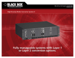
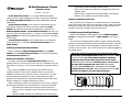
18-Slot Rackmount Chassis
Installation Guide
LMC5001A — LMC5002A
18-Slot Rackmount Chassis™ is a modular, SNMP-manageable
media converter chassis designed to be used in conjunction with Black
Box SNMP Manageable Modules (part numbers LMC5006C through
LMC5035C).
18-Slot Rackmount Chassis come in both AC (LMC5001A) and DC
(LMC5002A) versions and feature one slot for installing a Master
Module (LMC5003A) and 18 slots for installing any combination of
SNMP Manageable Modules. 18-Slot Rackmount Chassis ships with one
100-240 ±10% VAC (LMC5004AC) or -48 VDC (LMC5005DC) Power
Supply Module and features an additional slot for a second, redundant
power supply.
18-Slot Rackmount Chassis can be installed either as a managed or
unmanaged device. A managed 18-Slot Rackmount Chassis uses a
Master Module.
Installing 18-Slot Rackmount Chassis
Before installing any SNMP Manageable Modules and/or Master
Modules into the 18-Slot Rackmount Chassis, you should first install the
18-Slot Rackmount Chassis itself.
Rackmount Installation Instructions
To install a rackmountable 18-Slot Rackmount Chassis, you will
typically need four #10 screws and four clip nuts. (Hardware may vary
depending on rack type.) The rest of the hardware is supplied with the
unit.
First, mount the RETMA mounting ears to the chassis with the
supplied hardware. Then locate a suitable location in the rack for
installation and secure the clip-nuts onto the mounting rails. Use the
screws to attach the chassis to the rack. Finally, attach the cables
between the chassis and each device that will be interconnected, then
plug the chassis into a reliable, filtered power source.
When installing the chassis in an equipment rack, be sure to observe
the following precautions to prevent electrical or mechanical damage:
Stay within the chassis power rating to prevent overload of
supply circuits or damage to overcurrent protection and supply
wiring.
Maintain reliable earth ground, especially when connecting to
power strip instead of directly to branch circuit.
Protect your chassis from exposure to sunlight and electrical or
magnetic fields.
Ensure that the equipment rack remains stable, even with the
addition of the chassis and its associated cabling.
Tabletop Installation Instructions
Be sure that the unit is placed on a suitable flat surface, leaving some
space at the back of the unit to accommodate cooling. Attach the cables
between the chassis and each device that will be interconnected, then
plug the chassis into a reliable, filtered power source.
Configuring and Installing Modules
Refer to the installation guide shipped with the SNMP Manageable
Module for configuration information. Master Modules come ready to
install.
The process for installing these modules is simple. Remove the blank
bracket covering the slot where you’ll be installing the module. Slide the
module into the chassis, via the cardguides, until the module is seated
securely in the connector. Secure the module to the chassis by tightening
the captive screws.
NOTE: The first slot, located closest to the left-side of the chassis
(front view), is the management slot for the Master Module. Install
a Master Module only if using SNMP-management capabilities.
Otherwise, this slot must remain empty for the chassis and the
SNMP Manageable Modules to function properly. The 18 slots to
the right of the management slot are for SNMP Manageable
Modules. Do not install a SNMP Manageable Module in the
management slot or vice versa. SNMP Manageable Modules may,
however, be installed in any order within the 18 slots.
Figure 1: Installing a SNMP Manageable Module in an 18-Slot Rackmount Chassis
1
2
Connecting a Managed Chassis
A managed 18-Slot Rackmount Chassis is connected to the LAN via an
external 10Base-T hub connection. Connect a managed chassis to the
network by plugging one end of a twisted pair cable into the port
labeled “LAN” on the Master Module. Plug the other end of the twisted
pair cable into a device (e.g., switch, hub, etc.) in your existing 10 Mbps
Ethernet network.
LED Operation
SNMP Manageable Modules and Master Modules feature diagnostic
LEDs that provide information to help determine where failures reside
when they occur in your network. Refer to the installation guide
shipped with the module for LED information.
Installing Power Supply Modules
18-Slot Rackmount Chassis ships with one Power Supply Module
installed. It can operate on either AC or DC power, depending upon the
Power Supply Module(s) used. A second, redundant Power Supply
Module may be installed by removing the blank faceplate covering the
second slot on the rear of the unit. Note that both Power Supply
Modules must be of the same type — AC and DC cannot be mixed.
When removing a Power Supply Module for replacement, UNPLUG THE
POWER CORD to that module before sliding it out of the chassis.
Black Box Customer Service
Call: (724) 746-5500 Phone orders 24 hours a day, 7:00 AM
Monday to midnight Friday; 8:00 AM to 4:00 PM Saturday (EST)
Fax: (724) 746-0746 or in North America 1-800-321-0746
Mail order: Black Box Corporation, 1000 Park Drive, Lawrence,
PA 15055-1018
Technical Support and fax orders 24 hours a day.
Specifications
Environmental:
Operating Temperature: 32° - 104° F (0° - 40° C)
Storage Temperature: 22° - 160° F (-6° - 71° C)
Humidity: 5 - 95% (non-condensing)
Power:
AC Input Load: 100-240 VAC ±10%, 0.8/0.4A max.
DC Input Load: -48 VDC, 1.5A max.
Chassis Dimensions:
4.58” H x 17.42” W x 9.13” D (11.63cm H x 44.25cm W x 23.19cm D)
12.9 lbs (5.9 kg)
Heat Generation:
250 BTU/hr. maximum
Electrostatic Discharge Precautions
Electrostatic discharge (ESD) can cause damage to your add-in modules. Always observe the following
precautions when installing or handling an add-in module or any board assembly.
1) Do not remove unit from its protective packaging until you’re ready to install it.
2) Wear an ESD wrist grounding strap before handling any module or component. If you do not have a
wrist strap, maintain grounded contact with the system unit throughout any procedure requiring ESD
protection.
WARNING! Integrated circuits and fiber optic components are extremely susceptible to electrostatic discharge damage. Do not handle these components directly unless you are a qualified
service technician and use tools and techniques that conform to accepted industry practices.
3) Hold boards by the edges only; do not touch the electronic components or gold connectors.
4) After removal, always place the boards on a grounded, static-free surface, ESD pad or in a proper ESD
bag. Do not slide the board over any surface.
Warranty
Please contact Black Box for complete warranty information.
Federal Communications Commission Radio Frequency Interference Statement
This equipment has been tested and found to comply with the limits for a Class A computing device,
pursuant to Part 15 of the FCC Rules. These limits are designed to provide reasonable protection against
harmful interference when the equipment is operated in a commercial environment. This equipment
generates, uses and can radiate radio frequency energy and, if not installed and used in accordance with
the instruction manual, may cause harmful interference to radio communications. Operation of this
equipment in a residential area is likely to cause harmful interference in which the user will be required to
correct the interference at his own expense.
This digital apparatus does not exceed the Class A limits for radio noise emission from digital apparatus
set out in the Radio Interference Regulation of the Canadian Department of Communications.
Le présent appareil numérique n’émet pas de bruits radioélectriques dépassant les limites applicables aux
appareils numériques de classe A prescrites dans le Règlement sur le brouillage radioélectrique publié par le
ministère des Communications du Canada.
Safety Certifications
UL:
Listed to UL1950 and CSA 22.2, No. 950, Safety of Information Technology Equipment,
Including Electrical Business Equipment.
CE:
The products described herein comply with the Council Directive on Electromagnetic
Compatibility (89/336/EEC) and the Council Directive on Electrical Equipment Designed for
use within Certain Voltage Limits (73/23/EEC). Certified to EN 60950, Safety of Information
Technology Equipment, Including Electrical Business Equipment. For further details, contact
Black Box.
1000 Park Drive • Lawrence, PA 15055-1018 USA
TEL: (724) 746-5500 • FAX: (724) 873-7049
[email protected] • www.blackbox.com
© 2000 Black Box Corp. All rights reserved.
The information in this document is subject to change without notice. Black Box assumes no responsibility for any errors that
may appear in this document. Product names are trademarks of the manufacturer. Other brands or product names may be
trademarks and are the property of their respective companies.
Document Number 50-80935BB-00 A0
3
March 2000
4