1
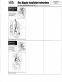
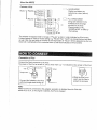
3 Positioning the various cords
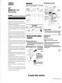
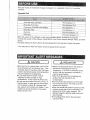
Components
(1) Adapter main unit
(2) Double-coated tape (2 pcs.) (3) Power cord
(4) Instruction manual
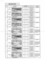
Remove the audio,
the floor console,the
side panel,etc.
iPod adapter
MODEL
MZ607411EX ( V-900IP-U )
Run the 13P DIN cable to
the back of the audio
space.
* When a 1DIN add-on
component will be
installed, also run the (3)
power cord together
with the DIN cable.
INSTALLATION MANUAL
WARNING
• Read these installation instructions thoroughly prior to starting installation work.
• Wiring should be performed after disconnecting the negative terminal of the battery.
Otherwise, electric shock or physical injury may occer.
• This equipment is only for vehicles equipped with 12V DC negative ground systems.
Do not install it in any vehicle equipped with a 24V system, such as a large truck or
diesel powered automobile equipped for cold regions. Such usage causes danger
of fire.
• All cords should be kept together to avoid interference with driving operations. It is
dangerous if they wind around the steering column, gear shift lever or brake pedal.
• If any cord comes in contact with a burr (sharp projection formed during the manufacture of parts) or any other sharp object, protect the cord by covering with tape
to avoid damage. Any damage to the covering may be a cause of fire or electric
shock.
• Never install in a manner that blocks front visibility, interferes with normal driving
operations of the steering wheel, gear shift lever or brake pedal or creates a danger
to any passenger in the case of a sudden stop. It may be the cause of a traffic accident or injury.
• Be sure to use all the accessory components as instructed and attach them securely. Never use a part other than that specified. Use of such a part may cause danger of damage to the internal components of the unit or loosening or detachment of
components.
• When attaching the ground to bolts or nuts attached to the vehicle, never use those
of any safety related component such as the steering, brake system or fuel tank.
Such usage may cause accidents.
• After completion of the wiring and installation work, ensure that all electric components, such as the brake system, lights, horn and turn signal lights operate normally
as before the installation. If operation is not normal, find the cause by checking the
wiring to make sure it is proper. Use with unknown problems may be the cause of
fire, electric shock and accidents.
• Never disassemble or modify the unit. It may be the cause of accident, fire or electric shock.
• If any abnormality, such as penetration by any foreign material, splashing, smoking
or if normal odors occur, stop use immediately and contact the dealer. Continuing
use may be the cause of accidents, fire or electric shock.
Existing harness
Remove the glove
compartment and
trim.
(5) Installation instructions
The slack harness should be
bundled up and attached to the
existing harness in the back of the
audio space in a way which will not
result in noise.
Run the dock connector into
the glove compartment and
run it so that about 20cm
can be pulled out.
Dock connector
( )
During use, connect the iPod
to the dock connector and put
it in the glove compartment.
(1) Adapter main unit
Needed Tools
Screwdriver
Tape measure
Ornament Remover
Check
Electrical Tape
4 About connections
The main points of connections will be different for each system. Please
refer to "Main Points Regarding Connection" on the back of this sheet.
Check
General main points regarding
installation
1 Setting of adapter main unit
The iPod adapter must be set ahead of time according to the system to
which it will be connected. Set the adapter main unit referring to the initial
settings on the back of this sheet.
2 Mounting adapter main unit
Top surface
Label
(1) Adapter main unit
Stick the (2) double-coated tape on the (1) adapter
main unit and stick them
to the mounting surface.
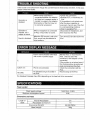
5 Operation check
1)Connect the iPod.
2)Operate the head unit to select the iPod.
3)Operate the head unit and check that the iPod sound is being
out-put.
If an iPod is not available, perform the following simple check.
1)Operate the head unit and select the iPod.
2)Check that the audio display shows the eject status display ("EJ", etc.)
If operation is not normal, recheck all connections and recheck the settings
of the adapter main unit.
*
Check
Check
Stick the (2) double-coated
tape to the bottom surface of the (1)
adapter main unit (the surface without
the label). If the (2) double-coated tape
will be stuck on the top surface, position the tapes so that they do not cover
the label.
(2)Double-coated tape (2 pcs.)
Bottom surface
Mounting surface
mb303
*
Caution
Wipe the area to which the tapes will be
stuck on clean and stick the tapes on
securely.
'06.05 I.P N871L65482 (1/2) Printed in Japan.
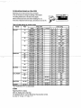
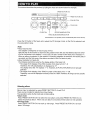
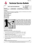
Main Points Regarding Connection
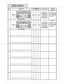
Initial settings
When connecting only the iPod adapter
Depending on the head unit that will be connected, it may be necessary to change the settings of this adapter. The setting
switches are on the side of the adapter. Set the switches as shown below before installing the unit. At the time of shipment from the factory, all switches are set to ON.
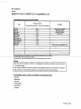
13P
iPod
Head unit
Switch section Switch
Name card
ONside
OFFside
Dock connector
Setting information
Not used
(1)Adapter main unit
13P
13P DIN connector
O
N
↑
Can be used to connect
An existing Satellite Radio(SIRIUSTM) .
1 2 3 4
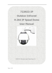
Details
(The head unit code is indicated on top or bottom surface.)
Switch settings
1
2
3
4
ON
ON
-
-
Album mode:Selects by the unit of Album and Play list.
-
-
ON
-
All songs mode:Selects by the unit of 100songs from all songs in
iPod.The listed head units be used only in All songs mode.
•MN141490 ( MONTERO,LANCER,LANCER SPORTBACK )
•MN141494 ( ECLIPSE,ECLIPSE SPYDER (~’05) )
•MN141488 ( MONTERO,MONTERO SPORT, OUTLANDER )
•MR587385 ( MONTERO SPORT,OUTLANDER )
•MN141496 ( GALANT )
•MR306775 ( GALANT )
-
-
OFF
-
When the head unit is equipped with a CD Scan function
-
-
-
ON
When the head unit is not equipped with a CD Scan function and
the Scan function will be used. 1
-
-
-
OFF
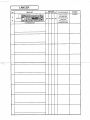
Setting according to con- Head unit code.
nected optional equipment
•MN141490 ( MONTERO,LANCER,LANCER SPORTBACK )
•MN141494 ( ECLIPSE,ECLIPSE SPYDER (~’05) )
•MN141488 ( MONTERO,MONTERO SPORT, OUTLANDER )
•MN587385 ( MONTERO SPORT,OUTLANDER )
•MN141496 ( GALANT )
•MR306775 ( GALANT )
•8701A011 ( ECLIPSE (’06~),ECRIPSE SPYDER(’07~) )
•8701A032 ( OUTLANDER )
•8701A045 ( ENDEAVOR,GALANT,ECLIPSE(’06~) )
•MN141259 ( ENDEAVOR )
Mode setting
• SIRIUS Satellite Inc. “SIRIUS” and related marks are trademarks of SIRIUS Satellite Radio Inc.
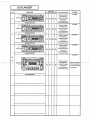
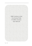
When connecting the iPod adapter and a 1DIN size add-on (6-disc CD changer) simultaneously
13P
20P
Head unit
13P
6-disc CD changer
iPod
Use tape, etc.
to protect the terminals.
Intermediate connector
(MZ598118EX; sold separately)
Scan function setting
*
(3)Power cord
1 The functions of the RPT or RPT/RDM buttons will be changed to Scan. As a result, RPT or RPT/RDM function cannot be used.
Fuse
BATT
Connect to BATT terminal.
(1)Adapter main unit
Vehicle-side 14P connector
Dock connector