1
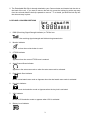
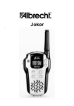
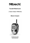
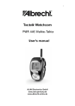
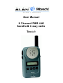
User Manual
8 Channel PMR 446
handheld 2-way radio
Tectalk
1
OPERATING INSTRUCTIONS
FUNCTIONS AND CONTROLS
1. Battery Door
2. Monitor Button
3. Detachable Belt Clip
4. Push-To-Talk (PTT) Button
5. Antenna
6. External Mic / Speaker
7. Built-in Speaker
8. LCD Panel
9. Built-in Microphone
10. Up Button & Volume Control
11. Down Button & Volume
Control
12. Function Button
13. Power On/Off & Enter Button
BATTERY INSTALLATION
Each Communicator unit operates on four ‘AAA’ size batteries.
1. Remove the Battery Door (#1) from the back cabinet by unclipping the lock at the bottom of the
door and lifting it upwards.
2. Following the polarity diagram shown inside the battery compartment, insert four ‘AAA’ size
batteries. Replace the
Battery Door (#1) and lock.
IMPORTANT: Be sure that the batteries are installed correctly. Wrong polarity may damage
the unit.
3. For better performance and longer operating time, we recommend the use of alkaline-type
batteries.
4. Do not mix old and new batteries.
5. Do not mix alkaline, standard (carbon-zinc) or rechargeable (Ni-MH) batteries.
6. If the unit is not to be used for an extended period of time, remove the batteries. Old or leaking
batteries can cause damage to the unit and will void the warranty.
WRIST STRAP AND DETACHABLE BELT CLIP INSTALLATION
The Wrist Strap and Detachable Belt Clip are provided to enable you to carry the
palm-sized Communicator easily and safely.
1. To use the Wrist Strap, simply attach it to the hole just above the Belt-clip (#3). Feed the small
loop on the end of the strap through the hole and then pass the strap through the loop and pull
tight.
2
2. The Detachable Belt Clip is already attached to your Communicator and locates into the slot on
the back of the unit. If you want to remove the belt clip, press the locking lug at the top away
from the unit and slide the belt clip upwards to remove. To re-install, just slide the belt clip into
the slot and snap in place.
LCD PANEL ICON DESCRIPTIONS
1.
RSSI (Receiving Signal Strength Indicator) or TX Bar Icon
Indicates the receiving signal strength and blinks during transmission.
2.
Monitor Indicator
Appears when the monitor button is used.
3.
CTCSS Indicator
Appears when the correct CTCSS tone is entered.
4.
Auto Channel Scan Indicator
Appears in the auto scan mode or when the auto scan mode is activated.
5.
Dual Watch Scan Indicator
Blinks in dual watch scan mode or Appears when the dual watch scan mode is activated.
6.
Key Lock Indicator
Blinks in auto lock selection mode or Appears when the key lock is activated.
7.
VOX Indicator
Blinks in VOX selection mode or appears when VOX is activated.
8.
Battery Level Indicator
3
Battery Level Meter indicates the remaining battery strength. If a battery becomes too weak
for transmit operation, You will be warned additionally by flashing the red LED every 5
seconds. At a too weak battery state the CPU may switch off the TX operation for some
seconds to allow the batteries to recover.
9.
Power Save Display
Blinks when the power save is activated. The rate at which the icon blinks varies with the
power saving ratio. Fast indicates a lower power saving while slow indicates a higher power
saving ratio.
10. Tx Indicator
Appears when a signal is being transmitted.
11. Rx Indicator
Appears when a signal is being received.
12. Large Segment Display
Indicates the channel number in use at the normal mode. When the Function Button is
pressed, it displays the function menu in sequence: CH / cTc / SC / dW / VO / Vdt / ALo /
CAL / ton
13. Small Segment Display
Displays the CTCSS tone option at the normal mode. CTCSS option is displayed in “Hz”.
Displays the SUBMENU of each MENU in the function mode. (e.g. CH 1-8 / cTc: hz / SC: up,
dn / dW: channel number / VO: high, off, low / Vdt 5sec, 3sec, 2sec, 1sec / ALo off, auto /
CAL number 1-7 / ton : no - freq )
CONTROL BUTTON FUNCTIONS
Power ON/OFF (#13) ( ↵ )
Power On - Short Touch
•
Press this button (#13) briefly to turn the unit on. A short confirming melody will play.
•
Power Off - Long Touch
Press this button (#13) for longer than 1.5 seconds to turn the unit off. A short confirming
melody will play.
ENTER BUTTON (#13) ( ↵ )
Press it to confirm the required option for respective functions during function edit mode.
Press it briefly in standby mode to convert the display of CTCSS sub code from frequency to
4
number or number to frequency in about 1 second.
PUSH-TO-TALK (PTT) BUTTON (#4)
1. Press it firmly and speak into the Built-in Microphone (#9) to transmit. The red Tx LED
Indicator at the right side of the LCD Panel (#8) will light.
2. Release it to revert to standby mode. When an incoming call is received, the green Rx LED
Indicator on the left side of the LCD Panel (#8) will light.
3. 2-Way Call Ringer: Press the PTT Button twice quickly to call another party on the same
channel. The word “CALL” and the Tx icon will appear in the display. The user selected call
ringer melody will play (see page 6 to change call melody). The Call melody can be switched
off with the same menu step to avoid accidential activation.
VOLUME CONTROL (#10 (5)& #11(6))
In the standby mode, adjust volume to a comfortable level by pressing the UP (#105) & the
DOWN button (#116) and adjusting the volume control at the same time.
UP BUTTON (#10) ( 5)
• Short Touch
In the standby mode, press this button briefly to move to the next higher main volume level.
In the function edit mode, press briefly to shift from the current option in each submenu to the
next option in the same submenu.
• Long Touch
Pressing this button for more than 1.5 seconds will allow you to navigate at a more rapid rate
through different volume level in the standby mode or through different menus in the function
edit mode.
DOWN BUTTON (#11) ( 6)
• Short Touch
In the standby mode, press this button briefly to move to the previous lower main volume
level.
In the function edit mode, press briefly to shift from the current option in each submenu to the
previous option in the same submenu.
• Long Touch
Pressing this button for more than 1.5 seconds will allow you to navigate at a more rapid rate
through different volume level in the standby mode or through different menus in the function
edit mode.
FUNCTION BUTTON (#12) ( F )
Short Touch
•
Press this button briefly to enter function edit mode in standby mode.
•
Long Touch
Press for longer than 1.5 seconds to activate or deactivate the KEY LOCK in the standby
mode. Please note all buttons will be disabled except the Monitor Button (#2) and PTT
Button (#4) will remain fully operational (see menu description to activate and disable the
auto key lock function).
MONITOR BUTTON (#2) (=disable automatic squelch)
• Press it to check activity on the current channel before you try to transmit.
5
•
•
•
•
You can use the Monitor button when You receive weak or interrupted signals. If You press
Monitor only for a short time, the squelch opens for the time pressed.
If You press the button longer than 7 seconds continuously, the squelch will remain open. You
may use this function if Your distant party’s signal remains weak for a longer time period.
Pressing again Monitor closes the squelch again.
Adjust the Volume Control (#10 5& #116) if necessary.
Other functions of the monitor button
•
•
•
•
•
When you press the Monitor Button, the LCD Panel (#8) will be illuminated with an amber
color back-light and both the Tx and Rx LED Indicators will light. After some seconds the LED
will switch off again.
If you press the Monitor Button during the function edit mode, you will return to standby mode
directly.
In the Auto channel scan mode, if you press it during Rx or scan wait time (about 5 seconds)
in specific channel, it skips the channel in the auto channel scan after that.
If You press Monitor longer during SCAN mode until You hear a beep tone, the channel will be
skipped during all following scan cycles, as long as scanning remains activated.
When you press it during VOX operation, discontinue it in about 10 seconds.
EXTERNAL MIC/SPEAKER (#6)
This jack accepts an optional headset/microphone for totally handsfree operation. Please refer to
the latest Albrecht accessory item listen in catalogue or internet (www.albrecht-online.de) or ask
Your dealer.
OPERATION / FUNCTION EDIT MODE
2. CHANNEL SELECT MODE
This feature allows you to select main channels to communicate with the party.
To access the Channel Select Mode,
- Press the Function Button (#12) until “CH” appears in the LCD Panel (#8).
- Press the Up Button (#10) or the Down Button (#11) to choose channels up or down from
the current channel
number.
- Press the Enter Button (#13) to confirm your selection.
3. CTCSS (Coded Tone Controlled Squelch System) SUBCHANNEL SELECTION MODE
This feature allows you to utilize a less used channel range (00-38) within a main channel.
This enables you to communicate with another party on the same main channel using the
same subcode. This helps to avoid congestion on the main channel and filters out unwanted
noise and static. There are 38 CTCSS subchannels for each main channel.
To change the CTCSS subchannel,
- Press the Function Button (#12) until the word “cTc” appears in the LCD Panel (#8).
- Press the Up Button (#10) or the Down Button (#11) to choose the desired subchannel to
use. The corresponding subcode frequency will be displayed in the lower right corner.
- Press the Enter Button (#13) to confirm your selection.
NOTE: To communicate with other PMR units, they must be switched to the same
channel and CTCSS subcode. To communicate with other PMR units that do not have
subcodes, switch your unit to the same channel with the subcode set to “OFF”.
6
4. AUTO CHANNEL SCAN MODE
This feature allows you to scan for an active channel and communicate with the party
transmitting.
To access the Auto Channel Scan menu,
•
•
•
•
•
•
•
•
Press the Function Button (#12) until the auto channel icon blinks and “SC” appears in the
LCD Panel (#8).
Press the Up Button (#10) or the Down Button (#11) to choose scanning up or down from the
current channel number.
Press the Enter Button (#13) to confirm your selection.
The unit will begin scanning for an active main channel. If a transmission is detected, the Rx
and RSSI icons will appear in the LCD Panel (#8).
To turn off the auto channel scan feature in the standby mode, simply press the Function
Button (#12) once.
Continuously busy or undesired channels can be skipped from scanning after scanner has
stopped on such a channel by pressing the MONITOR button:
Short pressing: channel will be skipped immediately for the same scan cycle
Long pressing (until You hear beep tone): channel will be skipped for all further scan cycles,
as long as scanning remains activated.
5. DUAL WATCH SCAN MODE
This feature allows you to monitor two different channels at the same time. If you pre-set any
priority channel other than the current channel in use, the pre-set channel will be scanned
every 0.5 second and signals you when a call is received.
To access the Dual Watch scan menu,
•
•
•
•
Press the Function Button (#12) until the dual watch icon blinks and “dW” appears in the
LCD Panel (#8).
Press the Up Button (#10) or the Down Button (#11) to select the desired channel number
you wish to closely monitor.
Press the Enter Button (#13) to confirm your selection.
To turn off the dual watch feature in the standby mode, simply press the Function Button
(#12) once.
6. VOX SELECTION MODE
The Voice Activated Transmission (VOX) function allows your voice to activate transmission
automatically when the Communicator is used with the optional handsfree mic/headset (refer
to enclosed Accessory Order Form). It also allows handsfree use when a mic/headset is not
being used without having to use the PTT Button (#4). The Vox menu allows not only
different vox sensing trigger levels, but is even coupled with automatic MIC sensitivities
dependimg on the surrounding noise conditions.
To access the VOX Selection menu,
• Press the Function Button (#12) until the VOX icon blinks and “UO” appears in the LCD
Panel (#8).
• Press the Up Button (#10) or the Down Button (#11) to select from High, Mid, low or OFF.
High, Mid or low setting determines VOX and mic response sensitivity. While High is for high
surrounding noise, this position has the lowest sensitivity and is designed for louder
7
•
•
•
speaking volules in such a high noise surrounding (preferable for motor bike drivers)
For baby monitoring use LOW position for highest sensitivity in the baby’s room.
Press the Enter Button (#13) to confirm your selection.
To turn off the VOX feature, enter the VOX selection mode and then select “OFF’’.
7. VOX RECOVERY TIME SELECTION MODE
This allows the response characteristics of the VOX function to be precisely adjusted to suit
individual needs.
To access the VOX Recovery Time Selection menu,
•
•
•
•
•
Press the Function Button (#12) until “Udt” appears in the LCD Panel (#8) with the VOX
icon blinking.
Press the Up Button (#10) or the Down Button (#11) to select from 5, 3, 2 or 1 second setting.
This setting determines the delay time between transmitting and receiving.
Press the Enter Button (#13) to confirm your selection.
Please note you may need to try different VOX time settings to determine the best value to
suit your speaking habit.
To turn off the VOX feature, enter the VOX selection mode and then select “Off’’.
8. AUTO KEY LOCK SELECTION MODE
This feature prevents accidental channel change and disturbance to the preferred settings of
the Communicator. Auto Key Lock temporarily disables the Up, Down and Enter Buttons.
To access the Auto Key Lock Selection menu,
•
•
•
•
•
•
Press the Function Button (#12) until the auto lock icon blinks and “ALo” appears in the
LCD panel (#8).
Press the Up Button (#10) or Down Button (#11) to select the “Auto” option.
Press the ENTER key to confirm your selection.
If you do not press any key for more than 15 seconds in the standby mode, all respective
keys will automatically be locked.
To turn the auto key lock on or off in standby mode, simply press and hold the Function
Button (#12) for more than 1.5 seconds.
To quickly activate the Key Lock, hold the Function Button (#12) for more than 1.5 seconds.
9. CALL RINGER MELODY (and Call OFF) SELECTION MODE
This feature provides 7 user selectable call ringer melodies to alert you of a calling party.
•
•
•
To select your favorite Call Ringer melody,
Press the Function Button (#12) until the call icon blinks and “CAL” appears in the LCD
panel (#8).
Press the Up Button (#10) or Down Button (#11) to preview the 7 available melodies or
select CAL OFF, if You do not desire to have this function (recommended for motor bike use).
Press the ENTER key to confirm your selection.
10. CTCSS SUB CODE DISPLAY SELECTION MODE
To select your favorite CTCSS sub code display, press the button in standby mode.
8
10. Beep tone switching
There is also a menu point which allows deactivation of the key beep tones. Beep tones are
good with loudspeaker operation, but should be switched off during ear phone operation.
•
•
•
Press the Function Button (#12) until the call icon blinks and “bEp ON” appears in the LCD
panel (#8).
Press the Up Button (#10) or Down Button (#11) to select between bEp ON and bEp OFF
use).
Press the ENTER key to confirm your selection.
11. Squelch tail noise elimination
A software switch can reduce the disturbing noise which happens after a distant party stops
transmission and releases the PTT button. The elimination function can be enabled among
tectalk models only and can reduce the noise burst in receive mode. Technically, the
transmission stop will be delayed for about 400 mseconds after releasing the PTT button.
The effect will be optimized together with CTCSS use.
•
•
•
Press the Function Button (#12) until the call icon blinks and “t Al OFF” appears in the LCD
panel (#8).
Press the Up Button (#10) or Down Button (#11) to select between tAl OFF or tAl ON.
Press the ENTER key to confirm your selection.
NOTES FOR GOOD COMMUNICATION
1. Your Communicator unit’s 8 channels are shared on a “take turns” basis. This means other
groups may be talking on any of the channels. A common code of ethics/courtesy is to
switch to another vacant channel and not to attempt to talk over someone who is already
using the channel you first selected.
2. Your Communicators have been designed to maximize performance and improve
transmission range in the field. To avoid interference, it is recommended that you do not use
the units closer than 5 feet apart.
3. For best transmission results, always keep your mouth about 2-3 inches from the
Microphone (#9) and speak slowly in a normal voice.
CARE AND MAINTENANCE
• Clean your unit with a damp (never wet) cloth. Solvent or detergent should never be used.
• Avoid leaving your unit in direct sunlight or in hot, humid or dusty places.
• Keep your unit away from heating appliances and sources of electrical noise such as
fluorescent
lamps or motors.
SPECIFICATIONS
Operating Main Channels
CTCSS Subchannels
Operating Frequency Range
Talk Range
Output Power
Power Source
8 CH (European international agreement)
38 for each main channel
UHF 446.00625MHz to 446.09375 MHz
Up to 2 –3 miles / 5 km
0.5 Watts max
‘AAA’ alkaline batteries X 4, 6 VDC
9
NiMH Rechargeable Battery AAA X 4, 4.8VDC
About 35 hours (5/5/90 duty cycle)
Battery Life
MAIN CHANNEL FREQUENCY TABLE (in MHz)
Main
Channel No.
1
2
3
4
5
6
7
8
Frequency
(in MHz)
446.00625
446.01875
446.03125
446.04375
446.05625
446.06875
446.08125
446.09375
CTCSS SUBCHANNEL FREQUENCY TABLE (in Hz)
CTCSS
Subchannel No.
1
2
3
4
5
6
7
8
9
10
11
12
13
14
15
16
17
18
19
Frequency
(in Hz)
67.0
71.9
74.4
77.0
79.7
82.5
85.4
88.5
91.5
94.8
97.4
100
103.5
107.2
110.9
114.8
118.8
123.0
127.3
CTCSS
Subchannel No.
20
21
22
23
24
25
26
27
28
29
30
31
32
33
34
35
36
37
38
Frequency
(in Hz)
131.8
136.5
141.3
146.2
151.4
156.7
162.2
167.9
173.8
179.9
186.2
192.8
203.5
210.7
218.1
225.7
233.6
241.8
250.3
CARE AND SAFETY
To assure optimal radio performance and to ensure RF energy exposure is within the guidelines
of the above standards, the following operating procedures should be observed:
FOR PORTABLE 2-WAY RADIOS
•
When transmitting with a portable radio, hold radio in a vertical position with its microphone 12 inches away from your mouth. Keep antenna at least 1 inch from your head and body.
10
•
If you wear a portable radio on your body, ensure the antenna is at least 1 inch from your body
when transmitting.
ELECTROMAGNETIC INTERFERENCE / COMPATIBILITY
Most electronic devices are susceptible to electromagnetic interference (EMI) if inadequately
shielded, designed or otherwise configured for electromagnetic compatibility.
• Turn off your radio in any facilities where posted notices instruct you to do so. Hospitals or
health care facilities may be using equipment that is sensitive to external RF energy.
• Turn off your radio when on board aircraft when instructed to do so. Any use of the radio must
be in accordance with airline regulations or crew instructions.
•
CAUTION
Damaged Antenna
Do not use any radio with a damaged antenna. If a damaged antenna comes in contact with the
skin, a minor burn may result.
Batteries
Do not short circuit exposed terminals of any batteries with any conductive materials. In doing so,
the material may become quite hot and cause property damage and/or body injury such as burns.
WARNING
Parts Replacement or Substitution
Replacement or substitution of parts other than those recommended by CP Tech may cause a
violation of the technical regulations of the ETS-300-296 Rules, or violation of Type Acceptance
requirements of the ETS-300-296 Rules.
Vehicles with an Air Bag
Do not place a portable radio in the area over an air bag or in the air bag deployment area. Air
bags inflate with great force. If a portable radio is placed in the air bag deployment area and the
air bag inflates, the radio may be propelled with great force and cause serious injury to occupants
of vehicle.
Potentially Explosive Atmospheres
Turn your radio off when in any area with a potentially explosive atmosphere, unless it is a type
especially qualified for such use. Sparks in such areas could cause an explosion or fire resulting
in body injury or even death.
Batteries
Do not replace or charge batteries in a potentially explosive atmosphere. Contact sparking may
occur while installing or removing batteries and cause an explosion.
11
Blasting Caps and Areas
To avoid possible interference with blasting operations, turn your radio off near electrical blasting
caps or in a “blasting area” or in areas posted:” Turn off 2-way radio”. Obey all signs and
instructions.
Areas with potentially explosive atmospheres are often, but not always, clearly marked.
Note:
They include fuelling areas such as below deck on boats, fuel or chemical transfer or storage
facilities; areas where the air contains chemicals or particles, such as grain, dust, or metal
powders; and any other area where you would normally be advised to turn off your vehicle engine.
Accessory – Desktop Charger
After removing the charger base and power supply from the packaging, plug the power supply’s
DC connector into the jack on the back of the base.
To charge a battery, simply place the radio into the front charging well. Cycle lasts up to 10 hours.
As option, a 12 V DC cable for Car use is available. This will allow charging the radio from car 12
V supply.
D.C Power Jack
Charging Well
European 2 years warranty
The distributor, dealer or retail shop warrants to the original retail purchaser of this product that should this
product or any part of it, under normal use and conditions, be proven defective in material or workmanship
within 2 years from the date of original purchase, such defect(s) will be repaired or replaced with new or
reconditioned product (at the company's option) without charge for parts and repair labor. To obtain repair
or replacement within the terms of this warranty, the product is to be delivered with proof of warranty
coverage (e.g. dated bill of sale), specification of defect(s), to the distributor, dealer or his authorized
repair center.
The Company disclaims liability for communications range of this product. The warranty does not apply to
any product or part there of which, in the opinion of the company, has suffered or been damaged through
alteration, improper installation, mishandling, misuse, neglect, accident, or by removal or defacement of
the factory serial number/bar code label(s). The warranty does not apply to accessory parts or problems
caused through not authorized or not recommended accessories like of the units like batteries, external
power supplies and over voltage caused through external power supplies, light bulbs, broken antennas,
broken swivel belt clips, broken or damaged acrylic glass windows and cabinet parts.
Please contact the dealer or person where You have purchased Your Tectalk.
12
Where to find service hints and documentation
The complete technical documentation is updated regularly. You can download the latest versions of user
manuals, technical documents and conformity declaration, as well as service hints or FAQ’s any time from
our server under
http://www.albrecht-online.de/service
If You should have a problem, please have a look to the service hints or frequently asked questions (FAQ)
before You send Your Tectalk back to the service center.
CE- Declaration of Conformity
Albrecht Tectalk / JDP-408 HX
This unit complies to all relevant European Standards and Regulations for PMR 446 radio service. This
radio may be used only in EU countries and some other states applying the R&TTE directive of the
European Community. However, there are still some restrictions (as of date of this user manual) to use
PMR 446 in following countries:
Italy and Norway:
PMR 446 is not yet established in these countries. Other radio services are still
legally using these frequencies. Travellers may take the radios with them, but
not operate them. Please ask local authorities for further informations!
France:
Channels 1 and 2 are not yet allowed to be used.
Belgium:
No restrictions for travellers using the radio in Belgium free of charge and
licence for less than 3 months. Residents of Belgium must apply for a radio
operating licence according to Belgian regulations.
Eastern Europe
Please ask the local authorities before using the radio, because only few
countries outside EU apply already the european R&TTE directive. Following
countries still apply special national approval regulations, not (yet) valid for PMR
446 radio Poland, Estonia, Letavia, Lithuania, Ukraine, Russia, Belarus,
Slowenia and some others.
This unit fully complies to the following European standards ETS 300 296, ETS 300 279, EN 60 950 . The
notified body 0499 (SEE Luxembourg) had been involved for the expert’s opinion about the conformity of
this radio. The unit is intended to be used in following European countries:
A, B, CH, CZ, D, DK, E, F, FIN, GB, GR, H, HR, IS, IR, L, NL, P, S, TR (JDP-408HX)
Lütjensee, 13.05.2002
ALAN Electronics GmbH
Note: The latest actual version of our „EC Declaration of Conformity“ may be downloaded from our Internet
server under http://www.albrecht-online.de/service .
© ALAN Electronics GmbH (05-2002)
www.albrecht-online.de
service-hotline:
service-fax:
service-e mail:
(+49) 4154 849 180
(+49) 4154 849 288
[email protected]
13