1
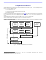
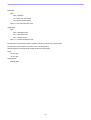
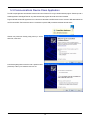
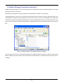
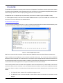
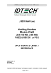
REG10J0134-0100
Renesas Starter Kit for H8SX1664
USB Sample Code User's Manual
RENESAS SINGLE-CHIP MICROCOMPUTER
H8SX FAMILY
Rev.1.00
Revision date 08.January.2008
Renesas Technology Europe Ltd.
www.renesas.com
Table of Contents
Table of Contents .................................................................................................................................................. ii
Chapter 1. Preface ..................................................................................................................................................3
Chapter 2. Introduction............................................................................................................................................4
Chapter 3. Development Environment....................................................................................................................5
3.1. Sample Code Configuration .........................................................................................................................5
3.2. Target Sample Code Options .......................................................................................................................5
3.3. Host Application Software ............................................................................................................................5
Chapter 4. USB Stack (Target)................................................................................................................................6
4.1. Hardware Abstraction Layer .........................................................................................................................6
4.2. USBCore ......................................................................................................................................................7
4.3. Human Interface Device Class.....................................................................................................................8
4.4. Communication Device Class ......................................................................................................................9
4.5. Mass Storage Class ...................................................................................................................................10
Chapter 5. Applications ......................................................................................................................................... 11
5.1. Introduction to Applications ........................................................................................................................ 11
5.2. Human Interface Device Application .......................................................................................................... 11
5.3. Communications Device Class Application ................................................................................................13
5.4. Mass Storage Class Demonstration ...........................................................................................................16
5.5. LibUSB .......................................................................................................................................................17
Chapter 6. Additional Information..........................................................................................................................19
ii
Chapter 1. Preface
Cautions
This document may be, wholly or partially, subject to change without notice.
All rights reserved. No one is permitted to reproduce or duplicate, in any form, a part or this entire document without the written
permission of Renesas Technology Europe Limited.
Trademarks
All brand or product names used in this manual are trademarks or registered trademarks of their respective companies or
organisations.
Copyright
© Renesas Technology Europe Ltd. 2007. All rights reserved.
© Renesas Technology Corporation. 2007. All rights reserved.
© Renesas Solutions Corporation. 2007. All rights reserved.
Website:
http://www.renesas.com/
Glossary
ADC
Analog to Digital Converter
USB
Universal Serial Bus
CPU
Central Processing Unit
DAC
Digital to Analog Converter
DMA
Direct Memory Access
E10A
“E10A for Starter Kits” debug module
FDT
Flash Development Tool
RSK
Renesas Starter Kit
LED
Light Emitting Diode
LCD
Liquid Crystal Display
3
Chapter 2.Introduction
The RSK USB sample code provides a basis for a developer to add USB device functionality to a system. It includes sample applications for
the three most common USB Device classes * :•
Human Interface Device (HID)
•
Communication Device Class - Abstract Control Model (CDC-ACM)
•
Mass Storage Class (MSC)
In addition to the three defined USB classes a LibUSB sample is included. LibUSB is an open source project with the aim of providing a library
that a user application can utilise to access a USB device regardless of operating system. A sample using a Microsoft Windows XP host is
provided.
The embedded software is available as source written in ANSI C and does not require an operating system.
The host applications software is also available as source written for MS Windows using VisualC++.
This manual describes the technical details of the RSK hardware. The Quick Start Guide and Tutorial Manual provide details of the software
installation and debugging environment.
Samples
Classes
HID
Demo
CDC
Demo
MSC
Demo
HID
CDC
MSC
LibUSB
Demo
USB Stack
USB Core Driver
HAL
USB Hardware
Figure 1 - Embedded SW, including Layers of USB Stack
* See specific sections for details. Tested with a USB Host PC running MS Windows XP SP2.
HID and
LibUSB samples both include a PC Application.
4
Chapter 3.Development Environment
3.1.Sample Code Configuration
The Sample code is provided as a project generator with the RSK. To create the sample code project follow the instructions in the RSK Quick
Start Guide.
When created the sample code will contain the source for both the Host and Target projects, including any configuration driver files.
3.2.Target Sample Code Options
When developing USB software it is useful to be able to get debug information out at runtime without stopping code from running such as
when stepping in a debugger. All modules of the USB Stack software include debug messages that can be utilised in a system that supports
printf. The sample Applications all support printf and the output is viewable via the serial port of the RSK. To view the serial output the
following settings are required:
Baud: 19200. Data: 8 Bit. Parity: None. Stop Bits: 1. Flow: None.
The level of debug message can be set using the #define VERBOSE_LEVEL. This is described in the file usb_common.h in the USBStack
directory. Note that a high level of debug messages can significantly slow down the system.
3.3.Host Application Software
To build the Microsoft Visual C++ Applications you will need to have the appropriate Windows Software Development Kit (SDK) and the
Windows Driver Development Kit (DDK) installed. These kits provide access to the library functions to access USB devices and are
available directly from Microsoft.
We have provided the links to the current locations for XP based downloads below however we cannot guarantee the suitability or accuracy
of these links. Both must be installed to be able to build the application, we suggest installing the SDK first.
www.microsoft.com/downloads
Windows SDK
Windows DDK
5
Chapter 4.USB Stack (Target)
The USB software is implemented in the form of a USB stack comprising of three layers.
At the top of the stack are the USB Device Classes consisting of HID, CDC and MSC which are all described later.
In the middle is a core layer (USBCore) that handles standard device requests. At the bottom is a hardware abstraction layer (HAL) that
provides a hardware independent API for the upper layers.
This modular design means this software can be still be used even if developing a proprietary USB interface. For example a proprietary
module could be implemented by calling functions directly exposed by both the USBHAL API and USBCore API.
4.1.Hardware Abstraction Layer
The HAL is a hardware specific layer that provides a non-hardware specific API. The HAL supports the following transfer modes:
Control (Setup, Data IN/OUT, Status)
Bulk (IN and OUT)
Interrupt (IN)
Some HAL implementations may not be able to support all these modes but the H8SX1664 implementation does.
Here is a list of the functions that make up the USBHAL API.
Name
Description
USBHAL_Init
Initialise the HAL. Register callback functions. If using the USB Core layer then this is done
automatically.
USBHAL_Config_Get
Get the current HAL configuration.
USBHAL_Config_Set
Set the current HAL configuration.
USBHAL_Control_ACK
Generate an ACK on the Control IN pipe. (Used following a setup packet)
USBHAL_Control_IN
Send data on the Control IN pipe. (Used following a setup packet)
USBHAL_Control_OUT
Receive data on the Control OUT pipe. (Used following a setup packet)
USBHAL_Bulk_IN
Send data on the Bulk IN pipe.
USBHAL_Bulk_OUT
Receive data on the Control OUT pipe.
USBHAL_Interrupt_IN
Send data on the Control IN pipe.
USBHAL_Reset
Reset this module. (Following an error).
USBHAL_Control_Stall
Stall the control pipe. (Used following a setup packet)
USBHAL_Bulk_IN_Stall
Stall the Bulk IN pipe.
USBHAL_Bulk_OUT_Stall
Stall the Bulk OUT pipe.
USBHAL_Interrupt_IN_Stall
Stall the Interrupt IN pipe.
USBHALInterruptHandler
The system must be setup so that this gets called when any USB Interrupt occurs.
The HAL module consists of the following files:usb_hal.c
usb_hal.h.
usb_common.h
6
4.2.USBCore
The USBCore layer handles standard USB requests common to all USB devices during the enumeration stage. This means that a developer
can concentrate on any class or vendor specific implementation. The USBCore requires initialising with the descriptors specific to the device
being implemented. It uses the USBHAL, which it initialises, to access the particular HW.
The following Get_Descriptor requests are handled:
Device
Configuration
String
Language ID (Only a single language ID is supported and this is currently English)
Manufacturer
Product
Serial Number
The USBCDC API consists of a single function called ‘USBCORE_Init’. This initialises the USBCore and the HAL. In addition to passing
device descriptors to this function it also requires call back functions for the following conditions:
A Setup packet has been received that this layer can’t handle. This enables a higher layer to handle class or vender specific requests.
A Control Data Out has completed following a setup packet that is being handled by the layer above.
The USB cable has been connected or disconnected.
An unhandled error has occurred.
The HAL module consists of the following files:usb_core.c
usb_core.h.
usb_common.h
7
4.3.Human Interface Device Class
The HID class as the name suggests is commonly used for things like keyboards, mice and joysticks where a human’s action is causing the
need for communication. However this does not need to be the case. The HID class is suitable for any device where the communication can
be achieved by sending data in ‘reports‘ of a predefined size where the data transfer rate is not critical.
The HID class has been supported by Microsoft Windows 98 onwards. Support is both at kernel level and user level. When a HID type device
is plugged into a Windows PC it will be automatically recognised and Windows will load its own drivers for it, so there is no need to develop
a custom Windows driver or even a Windows ‘inf’ file.
This implementation of the HID class supports a single IN report and a single OUT report. Both Interrupt IN and Control IN (via Get_Report)
transfers are supported for sending a report to the host. Reports from the host must use Control OUT (via Set_Report).
Here are the functions that make up the USBHID API.
Name
Description
USBHID_Init
Initialise the HID module. Register a callback functions to be called when a report is received from the host.
Provide the initial contents of a report to send to the host. Initialises the Core and HAL layers.
USBHID_ReportIN
Send a report to the host using Interrupt IN transfer.
The HID module consists of the following files:usb_hid.c
usb_hid.h.
usb_descriptors.c
usb_descriptors.h
usb_common.h
8
4.4.Communication Device Class
The CDC ACM allows a host to see a device as a standard serial (COM) port. This is particularly useful when working with legacy applications
that use serial communications. Bulk IN and Bulk OUT transfers are used for all non-setup data.
The CDC module utilises the USBCore layer for the processing of all standard requests. In addition it processes the following class requests.
GET_LINE_CODING
SET_LINE_CODING (As required by MS HyperTerminal)
SET_CONTROL_LINE_STATE
The CDC class is supported by MS Windows so there is no need to develop a custom Windows kernel driver. However a custom ‘inf’ file is
required, the sample CDC application includes such a file. When a CDC ACM device is plugged into a Windows PC an additional (virtual)
COM port will become available that applications can use just like a standard COM port.
Here are the functions that make up the USBCDC API.
Name
Description
USBCDC_Init
Initialise the CDC module. This also initialises the Core and HAL layers.
USBCDC_IsConnected
Returns the connected status of the device.
USBCDC_WriteString
A blocking function that sends a string to the host.
USBCDC_PutChar
A blocking function that sends a character to the host.
USBCDC_GetChar
A blocking function that gets a character from the host.
USBCDC_Write
A blocking function that sends a supplied data buffer to the host.
USBCDC_Write_Async
Starts an asynchronous write of a data buffer to the host. A call back is used to signal when the operation
has completed.
USBCDC_Read
A blocking function that reads from the host into a supplied data buffer.
USBCDC_Read_Async
Starts an asynchronous read from the host into a data buffer. A call back is used to signal when the
operation has completed.
USBCDC_Cancel
Cancel any asynchronous operations that are pending.
The CDC module consists of the following files:usb_cdc.c
usb_cdc.h.
usb_descriptors.c
usb_descriptors.h
usb_common.h
9
4.5.Mass Storage Class
The MSC class has become a very popular way for devices, such as cameras and USB Pens, to share data with PCs. The reason for the
success is that when the device is plugged in to a host PC it appears to the PC as just another drive and therefore users can use familiar
applications such as Windows Explorer to access the data. From Windows 2000 onwards the MSC class has been supported with no need
for custom drivers or ‘inf’ files.
Bulk IN and Bulk OUT transfers are used for all non-setup data.
The MSC module utilises the USBCore layer for the processing of all standard requests. In addition it processes the following class requests.
BULK_ONLY_MASS_STORAGE_RESET
GET_MAX_LUN
In addition to supporting the standard USB protocol a MSC device must support a set of SCSI commands. All SCSI commands are sent
packaged up in a Command Block Wrapper (CBW) within a Bulk OUT transfer. A data stage may follow in either direction and then to
complete the SCSI command the device sends a status response in the form of a Command Status Wrapper (CSW). The following SCSI
commands are supported:
INQUIRY
READ_CAPACITY10
READ10
REQUEST_SENSE
TEST_UNIT_READY
WRITE10
VERIFY10
PREVENT_ALLOW_MEDIUM_REMOVAL (Optional)
MODE_SENSE6 (Optional, Limited support)
The USBMSC API consists of a single function called ‘USBMSC_Init’. This initialises the MSC module and also the USBCore and HAL
layers.
This implementation of the MSC class directly accesses a simple RAM Disk block driver that uses 30KB of the RSK’s RAM. i.e. There is no
separation between MSC class and MSC application. Hence when using a different memory this will need to be changed to access that
rather than the sample RAM Disk.
The MSC module consists of the following files:usb_msc.c
usb_msc.h.
usb_msc_scsi.c
usb_msc_scsi.h
ram_disk.c
ram_disk.h
usb_descriptors.c
usb_descriptors.h
usb_common.h
10
Chapter 5.Applications
5.1.Introduction to Applications
The following sections introduce the sample applications that can be used to demonstrate each of the USB solutions. The HID and LibUSB
projects require specially written host applications that are supplied as both executables and as source. The CDC and MSC projects make
use of standard Windows applications.
All the applications require that the RSK has been programmed with the appropriate sample code for the application. Details of how to
program the RSK have been provided as part of the tutorial with the product. To obtain a digital copy of the manual please visit the Renesas
web site at www.renesas.com/renesas_starter_kits and select your RSK from the list.
5.2.Human Interface Device Application
The HID host sample application is written for a Windows host PC and is called RSK_HID.
The pre-built executable has been provided with the project generator. Navigate to the release directory under the project and run
RSK_HID.exe. The following window will be displayed:
Figure 2 - HID host PC application
Program the RSK with the HID application and run the code. Connect a USB cable between the PC and the RSK. The first time the device is
connected to a specific USB port windows will detect the new device and automatically load the intrinsic HID class driver.*
When windows has completed the enumeration process you need to make a connection from the application to the target. Click the
“Connect” button and you will be asked to confirm the VID and PID of the device you wish to connect with. If you have not altered the firmware
on the RSK to use your own VID and PID then the defaults will be correct. When a connection is successfully made information about the
device will be displayed and the rest of the buttons will be enabled.
The “Toggle LED” button enables a LED on the RSK to be toggled on and off.
The “Read ADC” button will command the RSK to read its ADC and return the value back to the host where it will be displayed.
The “Set LCD” button allows the text of the LCD on the RSK to be changed.
To demonstrate that the RSK can also instigate communications you can press a switch on the RSK and this will be indicated back to the host
resulting in a message being displayed on the dialog.
This demonstrates that Input and Output HID reports are being sent successfully between the RSK and the PC. The format of the reports is
as follows:
11
Input Report:
Byte 1
Bit 0 = LED status.
Bit 1 = ADC value valid indicator.
Bit 2 = Switch pressed indicator.
Byte 2-5 = 32 bit, little endian ADC Value.
Output Report:
Byte 1
Bit 0 = LED toggle request.
Bit 1 = ADC read request.
Bit 2 = LCD set request.
Byte 2-17 = 16 ASCII Characters for LCD.
An input report is sent whenever a switch on the RSK is pressed or when the host requests a report.
An output report is sent whenever a user clicks on one of the dialog buttons.
The HID application functionality specific to USB consists of the following files:Target:
usb_hid_app.c
usb_hid_app.h
Host Application:
\PC\RSK_HID\*
12
5.3.Communications Device Class Application
The CDC sample application demonstrates communication with a Windows PC using a standard terminal program. Windows provide a
suitable application called HyperTerminal. Any other serial terminal program will be able to be used if available.
Program the RSK with the CDC application and run the code as described in the RSK tutorial manual. Connect a USB cable between the
host PC and the RSK. The first time the device is connected to a specific USB port windows will detect the new device.
Windows will present the following dialog where you should
select “No, not this time”.
In the following dialog select “Install from a list or specific location
(Advanced)” to allow you to select the correct ‘inf’ file.
13
Either type or browse to the location of the CDC project you have
generated and built.
Press next to install the CDC support.
During the installation process a warning may be displayed as
shown. Please choose “Continue Anyway” to install the driver.
Please review the Microsoft website for details of the Windows
Logo Testing programme.
Windows will then complete the installation of the CDC USB
driver.
An additional COM port will become available to Window Applications. To be able to see the port that has been allocated you can open the
Windows Device Manager window. To do this go to the start menu and select run. In the dialog displayed type “devmgmt.msc”. This will
open the device manager. Expand the group of serial ports and the installed ports will be listed. When the Serial Terminal program
connects to this COM port * , it will receive a repeating message from the RSK saying:
“Renesas USB CDC Sample, Press Switch SW1.”
*
Note that the configuration settings for such things as baud rate and parity are irrelevant for this virtual COM port.
14
Pressing SW1 on the RSK will stop this repeating message and will bring up the main menu as shown below.
To demonstrate two way communication press SW2 to put the RSK into echo mode. In this mode anything typed on the Terminal will be
read by the RSK and then echoed back to the terminal. Pressing SW3 cancels this echo mode.
Figure 3 - Serial communication dialog
The CDC application functionality specific to USB consists of the following files:Target:
usb_cdc_app.c
usb_cdc_app.h
Host:
\PC\ CDC_Demo.inf
Note that the configuration settings for such things as baud rate and parity are irrelevant for this virtual COM port.
15
5.4.Mass Storage Class Demonstration
The MSC sample demonstrates how a host can view a MSC device as an external drive. There is no additional application for this as the
MSC support is inherent in Windows XP.
Start the MSC sample application running on the RSK then connect the RSK to a Windows PC via a USB cable.
Using Windows Explorer, or similar, look to find the new drive that Windows will have mounted. This drive is viewing the contents of the
sample RAM Disk on the RSK. It has been formatted with a FAT file system and given a volume name of “RENESAS”. The available space
for data is 4KB. It includes one example file called Renesas.txt which can be opened edited and saved. As you would expect from a normal
drive you can also copy files to it, although remember that this is a RAM Disk that will loose its contents when power is removed from the
RSK.
Figure 4 - Windows Explorer showing new Disk Drive mapping
There is an option in file ‘ram_disk.c’ that will prevent the RAM disk from initialising itself with a file system. To select this comment out the
#define of FORMAT_WITH_FAT_Example. In this case Windows will report that the drive is not formatted and give the user the option of
formatting it.
16
5.5.LibUSB
The LibUSB sample application is functionally similar to the previous HID application. The difference is that this sample includes software
for a Windows host PC called RSK_LibUSB. The intention of this open source library is to provide a platform independent operating system
interface allowing a device to be used on multiple operating systems with a common code base.
The target RSK code is not dependant upon any external library code however it is written to support the LibUSB functionality.
To use the supplied host SW you will need to have installed LibUSB-Win32 which is a port of the LibUSB code for Windows 32 bit
environments. This can be obtained from the LibUSB32 web site:
http://libusb-win32.sourceforge.net/
You can then build the supplied Microsoft Visual C++ project or use the pre-built executable which is located in the release directory under
the project and called RSK_LibUSB.exe. Run it and the following Window will be displayed:
Figure 5 - LibUSB application window
Note: This is a screen shot after a connection has been made and the ‘Read ADC’ button and the ‘Set LCD’ button have been used.
Program the RSK with the LibUSB sample code as described in the RSK tutorial manual. Then run the code. Connect a USB cable
between the host PC and the RSK. The first time the device is connected to a specific USB port Windows will detect the new device and
ask for the appropriate driver. This has been provided in a subdirectory of the sample code. Following the same process as described in the
Communications Device Class Application above navigate to the LibUSB driver as described and install it.
It should now be possible to make a connection from the application. Click the “Connect” button and you will be asked to confirm the VID
and PID of the device you wish to connect with. If you’ve not altered the firmware on the RSK to use your own VID and PID then the defaults
will be correct. When a connection is successfully made information about the device will be displayed and the rest of the buttons will be
enabled.
1.
The “Toggle LED” button enables a LED on the RSK to be toggled on and off.
2.
The “Read ADC” button will command the RSK to read its ADC and return the value back to the host where it will be
displayed.
17
3.
The “Set LCD” button allows the text of the LCD on the RSK to be changed.
To demonstrate that the RSK can also instigate communications you can press a switch on the RSK and this will be indicated back to the
host resulting in a message being displayed on the dialog.
This demonstrates that data can be sent successfully between the RSK and the PC. A fixed sized format of data has been chosen for all
messages, one for OUT and one for IN:
IN Message: (RSK to PC)
Byte 1
Bit 0 = LED status.
Bit 1 = ADC value valid indicator.
Bit 2 = Switch pressed indicator.
Byte 2-5 = 32 bit, little endian ADC Value.
OUT Message: (PC to RSK)
Byte 1
Bit 0 = LED toggle request.
Bit 1 = ADC read request.
Bit 2 = LCD set request.
Byte 2-17 = 16 ASCII Characters for LCD.
An IN message is sent whenever a switch on the RSK is pressed.
An OUT message is sent whenever a user clicks on one of the dialog buttons.
The LibUSB application consists of the following files:libusb_app.c
libusb_app.h
usbdescriptors.c
\PC\RSK_LibUSB\*
18
Chapter 6.Additional Information
For details on how to use High-performance Embedded Workshop (HEW), refer to the HEW manual available on the CD or installed in the
Manual Navigator.
For information about the H8SX/1664 series microcontrollers refer to the H8SX/1663 Group Hardware Manual
For information about the H8SX/1664 assembly language, refer to the H8SX Series Programming Manual
For information about the E10A Emulator, please refer to the H8S, H8SX Family E10A-USB Emulator User’s Manual
Further information available for this product can be found on the Renesas website at:
http://www.renesas.com/renesas_starter_kits
General information on Renesas Microcontrollers can be found on the following website.
Global: http://www.renesas.com/
19
Renesas Starter Kit for H8SX1664
USB Sample Code User's Manual
Publication Date Rev.1.00 08.Jan.2008
Published by:
Renesas Technology Europe Ltd.
Dukes Meadow, Millboard Road, Bourne End Buckinghamshire
SL8 5FH, United Kingdom
©2008 Renesas Technology Europe and Renesas Solutions Corp., All Rights Reserved.
Renesas Starter Kit for H8SX1664
USB Sample Code User's Manual
Renesas Technology Europe Ltd.
Dukes Meadow, Millboard Road, Bourne End Buckinghamshire SL8 5FH, United Kingdom