1
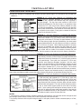
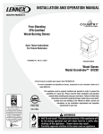
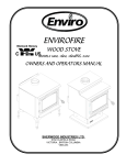
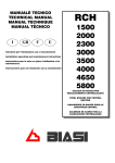
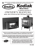
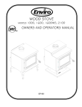
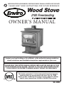
SHERWOOD INDUSTRIES IS AN ENVIRONMENTALLY RESPONSIBLE COMPANY. THIS MANUAL IS PRINTED ON RECYCLED PAPER.
PLEASE KEEP THESE INSTRUCTIONS FOR FUTURE REFERENCE
Wood Stove
2100 Freestanding
BY: SHERWOOD INDUSTRIES LTD
OWNER’S MANUAL
Contact your local building or fire officials, or the authority having jurisdiction
about restrictions and installation inspection requirements in your area.
PLEASE READ THIS ENTIRE MANUAL BEFORE INSTALLATION AND USE OF THIS
WOOD BURNING ROOM HEATER. FAILURE TO FOLLOW THESE INSTRUCTIONS
COULD RESULT IN PROPERTY DAMAGE, BODILY INJURY OR EVEN DEATH.
This heater meets the U. S. Environmental Protection Agencies
emission limits for wood heaters sold after July 1st, 1988.
Under specific conditions this heater has been shown to deliver
heat at rates ranging from 11,800 to 34,000 BTU per hour.
50-1084
Safety Precautions
FOR SAFE INSTALLATION AND OPERATION OF YOUR “ENVIRO” WOODSTOVE,
PLEASE CAREFULLY READ THE FOLLOWING INFORMATION:
● Please read this entire manual before you install and use your new heater. Failure to follow these
instructions may result in property damage, personal injury, and even death.
● If this appliance is not properly installed, operated and maintained a serious house fire could result. Do
not use any makeshift materials during installation.
● Never place wood, paper, furniture, drapes or other combustible materials near the stove, or let children
or pets touch it when it is hot.
● Operate only with the door and ash pan tightly closed and burn wood directly on the stove floor. Do not
operate if the door glass is broken or a gasket is missing or damaged. Do not alter the combustion air
control valves. Dangerous overfiring could occur which could ignite creosote in the chimney or cause
a house fire.
● At least 12 inches2 (77.4 cm2) of fresh outside air should be admitted into the room or directly to the
stove through a 4 inches (10.16 cm) diameter pipe. It would be dangerous to operate the stove with
the combustion-air inlet closed.
● Do not burn coal or charcoal as there is a danger of carbon monoxide being produced. Do not use
chemical fluids to start or re-fresh the fire. Do not burn garbage or flammable fluids such as gasoline,
grease, naphtha or engine oil. Never let the stove become hot enough to get any part red or glowing
red.
● Burning wet unseasoned wood could cause excessive creosote accumulation. When ignited it could
cause a chimney fire that could result in a serious house fire.
● Do not use grates, andirons or any other methods to support or raise the fire up off the hearth of the
appliance.
● In installations where there is constant or frequent high winds, install a flue damper to reduce the effect
that high winds have on increasing the draft. A significant increase in draft due to high winds may
cause your unit to overfire, which could be hazardous and will void the warranty.
2
Table of Contents
Safety Precautions.........................................................................................................2
Table of Contents...........................................................................................................3
Operating Instructions....................................................................................................4
Building Your Fire......................................................................................................5
How It Works............................................................................................................8
Specifications................................................................................................................9
Woodstove Specifications..........................................................................................9
Clearances To Combustibles - Freestanding.................................................................9
Installation..................................................................................................................10
Pedestal Installation................................................................................................10
Legs And Ash Pan Installation..................................................................................10
Chimney Installation Through Wall...........................................................................11
Installation...........................................................................................................12
Outside Air..............................................................................................................13
Installation Of A Listed, Factory Built Chimney...........................................................13
Brick Placement......................................................................................................14
Door Installation.....................................................................................................15
Optional Fan Installation..........................................................................................16
Wiring Diagram.......................................................................................................16
Parts List.....................................................................................................................17
Parts Diagram..............................................................................................................18
Warranty.....................................................................................................................19
Installation Data Sheet.................................................................................................22
3
Operating Instructions
FIRST START
When first installed, the chimney, firebricks and steel are cold and it usually takes several hours on a
fairly high burn for them to become hot and dry enough for the stove to function well. The paint will
smell a little for the first time or two as it cures. You may wish to open a door or window to eliminate
the smell.
DRAFT CONTROL:
Located on the front of the stove just below the ash sill is the Slider Air Damper. This damper will control
the amount of air to the fire. Pull this control all the way out when first starting the stove. Once the fire
has been established you may adjust this control to set the burn rate of the fire. If this damper is closed
at first start up the fire will burn very slowly and could soot the appliance.
FANS:
All models have been approved for operation with or without the optional fans supplied by the
manufacturer. On medium or high burns, using a fan will increase the heat transfer slightly. Route the
power supply cord along the floor behind the stove where it will remain cool.
DISPOSAL OF ASHES:
If you let the ashes accumulate two or three inches on the floor they tend to burn themselves up. Open
the small trap door located on the floor of the unit. Push the ashes that have accumulated into the hole
were the ashes would drop into the ash pan. Ensure that the trap door is closed properly before relighting
the unit. When necessary put the ashes in a metal container with a tightly fitting lid. Place the closed
container on a non-combustible floor, well away from combustible materials. If the ashes are to be buried
in soil or otherwise locally dispersed, keep them in a closed container until all cinders have cooled. If your
model has an ash pan, be sure to latch the ash pan tightly when finished. Small amounts of cold wood
ash can be used in the garden or compost.
REPLACING THE GLASS:
Never strike or slam the door, hit the glass or let burning wood rest against it. If the glass cracks when
the fire is burning, do not open the door until the fire is out and do not operate the stove again until
the glass has been replaced, preferably by your dealer. To remove the door, open and lift. To replace the
glass, remove the steel retaining clips and all loose glass. Replace only with Neoceram 5 mm glass selfadhesive fiberglass gasket; The use of substitute materials is prohibited use only part 10-000.
FIRE EXTINGUISHER AND SMOKE DETECTION:
All homes with a solid fuel burning stove should have at least one fire extinguisher in a central location
known to all in the household, and at least one smoke detection devise in the room containing the stove.
If it sounds the alarm, correct the cause but do not deactivate or relocate the smoke detection devise.
CREOSOTE - ITS FORMATION AND REMOVAL:
When wood is burned slowly, it may produce tar and other vapors that combined with moisture form
creosote. These vapors condense in the relatively cooler chimney flue of a slow burning fire, and if
ignited, make an extremely hot fire. So, the smoke pipe and chimney should be inspected bi-weekly
during the heating season to determine if a build-up has occurred. If creosote has accumulated it should
be removed to reduce the risk of a chimney fire.
4
Operating Instructions
CHIMNEY OR RUN AWAY FIRE:
1. Call local fire department (or dial 911)
2. Close the draft fully
3. Examine flue pipes, chimney, attic, and roof of the house, to see if any part has become hot enough
to catch fire. If necessary spray with fire extinguisher or water from the garden hose.
4. Do not operate the stove again until you are certain the chimney and its lining have not been
damaged.
MAINTENANCE:
At the end of each heating season clean the chimney and the smoke pipe. If soot has accumulated above
the top baffle bricks, remove, clean, and then replace them. If the secondary air tube is badly eroded,
replace it. Replace worn door gaskets and broken bricks as needed.
FAILURE TO INSPECT AND CLEAN YOUR CHIMNEY SYSTEM REGULARLY CAN RESULT IN A
CHIMNEY FIRE, WHICH COULD DAMAGE THE CHIMNEY OR CAUSE A HOUSE FIRE.
BUILDING YOUR FIRE:
Proper operation of your stove will help to ensure safe, efficient heating. Please take a few moments to
review these simple operating procedures.
1. Fuel Selection:
This stove is designed to burn natural wood only. Higher efficiencies and lower emissions generally
result when burning air-dried seasoned hardwoods, as compared to softwoods or to green or freshly cut
hardwoods. DO NOT BURN the following: treated wood, coal, garbage, solvents, colored papers, or trash.
Burning these may result in the release of toxic fumes and may poison or render the catalytic ineffective.
Burning coal, cardboard, or loose paper can produce soot, or large flakes of char or fly ash that can coat
the combustor, causing smoke spillage into the room, and rendering the combustor ineffective.
2. Building/Maintaining a Fire:
a) Open the primary air slide by pulling it all the way to the right.
b) Place a base of crumpled uncolored newspaper in the bottom of the stove. Lay pieces of kindling on
top of the newspaper and light it.
CAUTION: “Never use gasoline, gasoline-type lantern fuel, kerosene, charcoal lighter fluid,
or similar liquids to start or “freshen up” a fire in this heater. Keep all such liquids well
away from heater while it is in use.
c) As the kindling begins to burn, add several larger pieces of wood until the fire is burning well. At this
point, regular size logs may be added.
NOTE: Until the fire is burning well, leave the draft controls fully open.
d) Regulate the heat output of the stove by adjusting the draft controls to allow a larger fire and vice
versa. A short period of experimentation with the control settings will allow you to regulate the heat
output to keep your home comfortable.
Do not use a grate or elevate the fire. Build wood fire on the stove firebox hearth floor.
5
Operating Instructions
3. Refueling the Stove:
Use a long pair of gloves (barbecue gloves) when feeding the fire because these stoves burn at the front
they are clean and efficient, but they are also very hot and gloves are useful. Keep a small steel shovel
and whisk nearby for moving a log or lifting a fallen ember and for keeping the hearth clean.
a) Before attempting to add fuel to the stove, OPEN the damper control fully by pulling it all the way out.
This allows the chimney to carry away the additional smoke, which occurs when the door is open.
b) DO NOT OVERLOAD THE STOVE. Normally, three or four logs will provide heat for several hours.
Never operate this stove where portions glow red hot.
c) DO NOT OVERFIRE. If the heater or chimney connector glows, you are overfiring.
d) CAUTION: DO NOT PLACE FUEL WITHIN SPACE HEATER INSTALLATION CLEARANCES OR WITHIN
THE SPACE REQUIRED FOR CHARGING AND ASH REMOVAL.
4. For Maximum Efficiency:
When the stove is hot, load it fully to the top of the door opening, and burn at medium low settings.
When the fuel is mostly consumed, leaving a bed of red coals, repeat the process. Maximum heat for
minimum fuel occurs when the stove top temperature is between 250 °F (120 °C) and 550 °F (290 °C).
The most likely causes of dirty glass are: not enough fuel to get the stove thoroughly hot, burning green
or wet wood, closing the draft until there is insufficient air for complete combustion, or a weak chimney
draw. Indeed, the cleanness of the glass is a good indicator of the stove operating efficiently.
Helpful Hints Worth Repeating
1. Helpful advice on the correct way to start your fire.
a) You will need small pieces of dry wood, called kindling, and paper. Use only newspaper or paper
that has not been coated or had other materials glued or applied to it. Never use coated (typically
advertising flyers) or coloured paper.
b) Always open the door of the woodstove slowly to prevent suction and drawing smoke into the room.
c) Crumple several pieces of paper and place them in the center of the firebox and directly onto the
firebricks of the wood stove. Never use a grate to elevate the fire.
d) Place small pieces of dry wood (kindling) over the paper in a “teepee” manner. This allows for good
air circulation, which is critical for good combustion.
e) Light the crumpled paper in 2 or 3 locations. Note: It is important to heat the air in the stovepipe for
draft to start.
f) Fully open the air controls of the wood stove and close the door until it is slightly open, allowing for
much needed air to be introduced into the firebox. Never leave the door fully open, as sparks from
the kindling may fly out of the stove, causing damage or injury. As the fire begins to burn the kindling,
some additional kindling may be needed to sustain the fire. DO NOT add more paper after the fire has
started.
g) Once the kindling has started to burn, add some smaller pieces of seasoned, dry firewood. Note:
Adding large pieces at the early stages will only serve to smother the fire. Continue adding small pieces
of seasoned dry firewood, keeping the door slightly open until each piece starts to ignite. Remember
to always open the door slowly between placing wood into the fire.
h) Once the wood has started to ignite and the smoke has reduced, close the wood stove door fully. The
reduction of smoke is a good indication that the draft in the chimney has started and good combustion
is now possible. Larger pieces of seasoned, dry firewood can now be added when there is sufficient
space in the firebox. Adjust the air control setting to desired setting. Note: The lower the air control
setting, the longer the burn time of your firewood.
6
Operating Instructions
2. What type of wood is best to use as firewood?
Both hardwood and softwood burn well in this stove. Both woods contain about 8,000 BTU/lb (18,570
KJ/Kg), but hardwood is generally denser, will weigh more per cord, and burns a little slower and longer.
Cutting firewood so that it will fit horizontally, front to back, makes it easier loading and less likely for
the fuel to roll on the glass. Except for a cold start, there is no need to crisis-cross the logs. Ideal length
would be about 18“ (3457 mm) for the 2100. Burn only dry, seasoned wood. It produces more heat and
less soot or creosote. Freshly cut wood has about 50% moisture. A 10 pound (4.5 Kg) log contains 5
pound (2.3 Kg) of water. To season firewood split and stack it so that air can get to all parts of the wood.
Burn beach wood only if its salt content has been washed away in a season of rain and then the wood
dried. To prevent smoke spillage, when refueling, open the door slowly.
3. What does dry, seasoned wood mean?
Wood that has been dried for a period of one year in a well-ventilated and sheltered area would be
considered dry, seasoned wood. Wood from slow-growing trees is generally considered better than
wood from fast-growing trees. To season firewood split and stack it so that air can get to all parts of the
wood.
4. Will following the above-listed steps for starting a fire mean perfect results every time?
The quick answer is ‘most of the time’. There are many variables that may affect your success when
starting a fire. Most of those variables and how to deal with them will be learned through experience.
Your ability to start a good fire will significantly increase with time and patience. Some of the reasons for
poor stove performance will be covered in the next section of these instructions.
5. Why can’t I get the fire lit?
Damp or wet wood and poor drafts are the main reasons for poor results in starting a fire. Always use
dry, seasoned wood for your fire. Even wood dried for two years will be difficult to ignite if it has become
wet.
6. Is it normal for soot to cover the glass at the beginning of a fire?
Your stove has been built with an air-wash system that will help keep the glass clear when the firebox
has reached a good operating temperature and has a good draft. Normally a hot stove will keep the glass
clean, but if you must clean the glass, use a soft cloth with no abrasive and clean only when cold. Cold
firebox temperature and poor draft cause sooting of the glass. Once the firebox temperature and the
draft increase, the soot will burn off.
7. What is draft?
Draft is the ability of the chimney to exhaust or draw smoke produced during the normal combustion
process. Too much draft may cause excessive temperatures in the appliance and may damage the
appliance*. Inadequate draft may cause backpuffing or “plugging” of the chimney. There is a certain
amount of draft that is required to allow for your stove to function at its’ highest efficiency. A water
column gauge can be used to reference this amount.
7
Operating Instructions
8. What can cause a poor draft?
The most common factors for poor draft are:
a) Air supply
b) Environmental conditions
c) Cold chimney temperature
d) Poor chimney installation and maintenance
e) Atmospheric pressure
a) Air supply – Inside the home, normal household appliances such as clothes dryers and forced-air
furnaces compete for air, resulting in air starvation to the fire. This creates a condition in the house
known as negative pressure. When a house experiences negative pressure, the combustion gases
can be drawn from the chimney and into the house. This condition is commonly referred to as down
drafting. Increased amounts of insulation, vinyl windows, extra caulking in various places and door
seals can all keep heat in but may also make a home too airtight. An easy way to stop negative
pressure in a home is to crack a window in the room containing the stove.
b) Environmental Conditions - High trees, low-lying house location such as in a valley, tall buildings or
structures surrounding your house and windy conditions can cause poor draft or down drafting.
c) Cold Chimney Temperature - Avoid cold chimney temperatures by burning a hot fire for the first fifteen
to forty minutes, being careful not to over-fire the stove. If any part of the chimney or parts of the
stove starts to glow, you are over-firing the stove. Where possible, install a temperature gauge on the
chimney so temperature drops can be seen.
d) Chimney Installation and Maintenance - Avoid using too many elbows or long horizontal runs or height
of your chimney. If in doubt, contact a chimney expert and/or chimney manufacturer for help. Clean
chimney, rain caps and especially spark arrestor regularly, to prevent creosote build-up, which will
significantly reduce chimney draw and possibly a chimney fire.
9. Should I close or open the air control fully when shutting down the stove?
When shutting down the stove, fully open the air control. This allows the chimney temperatures to
remain as high as possible for as long as possible. Cold chimney temperatures create creosote.
Note: These instructions are intended as an aid and do not supercede any local, provincial or state
requirements. Check with officials or authorities having jurisdiction in your area.
HOW IT WORKS:
Double layer of Clayburn.
Insulated bricks keep a
high temperatures below
to burn up smoke.
Secondary air tube
and baffle.
Secondary air enters
at the bottom, it travels
up the rear vertical riser
into the top secondary
air tube, and out the
holes to burn up the
smoke.
Secondary air intake.
8
Primary air
window wash.
Smoke path
Dry seasoned wood
Primary air enters
at bottom, travels
up the side vertical
risers and down the
window.
Bottom (primary)
air outlet.
Single rod controls
for both openings.
Primary air intake.
Specifications
WOOD STOVE SPECIFICATIONS:
Model
2100 Freestanding
Width x Depth
24” x 30” (610 mm x 762 mm)
Height with pedestal or legs
33” (838 mm)
Height of body
22” (559 mm)
Fire box size (depth x width x height)
Capacity
211⁄2” x 18” x 12” (546 mm x 457 mm x 305 mm)
3.1 feet3 (0.0878 meter3)
2100 feet2 (195.1 meter2)
* Approximate heating area
**E.P.A. output rating
11,800 to 34,000 BTU/hour (3,455 to 9,956 watt)
*Duration on low burn
9 to 11 hours
Weight without bricks
414 pound (188 Kg)
Weight of bricks
103.2 pound (46.8 Kg)
E.P.A. Emissions
2.9 grams/hour (0.102 oz/hour)
* Figures Will Vary Considerably With Fuel And Conditions.
** E.P.A. output is calculated from a load of fir averaged from start until entirely consumed. The actual
heat output with refueling is very much greater.
CERTIFICATION: these stoves have been tested and listed by Intertek (ITS) (WH) to standards CSA
B366.2/ULC-S627, ULC-S628-M93, UL 1482-1994.
CLEARANCES TO COMBUSTIBLES - FREESTANDING:
MAINTAIN THESE MINIMUM CLEARANCES TO UNSHIELDED COMBUSTIBLES*
† FLOOR PROTECTION: If a stove is installed on a combustible floor, it must
have a pedestal attached and be on a NON COMBUSTIBLE hearth pad.
�
�����
�
������
���� ����
�
�
�
�
�����
�������� ����
�
�
�
��
��
�
CAUTION: An uninsulated smoke pipe must not pass through an attic, roof space,
closet or similar concealed space, or through a floor, ceiling, wall, or
partition, or any combustible construction.
�
���� ����
From side wall to side of unit
From rear wall to back of unit
From adjacent wall to corner of unit
From side wall to collar
From rear wall to collar
From adjacent wall to collar
† From front of unit to edge of hearth pad
† From side/back of unit to edge of hearth pad
�������� ����
A
B
C
D
E
F
G
H
With Single Wall Pipe
22” (559 mm)
12” (305 mm)
8” (203 mm)
31” (787 mm)
161⁄2” (419 mm)
19” (483 mm)
18” (457 mm)
8” (203 mm)
�
9
Installation
Please read and understand these instructions before installing pedestal or ash pan and leg option.
Failure to follow these instructions carefully could cause personal injury or property damage.All screws
are pre installed on the base of the unit.
PEDESTAL INSTALLATION:
• Remove the bricks from the unit before starting.
• Loosen the two (2) carriage bolts that secure the
unit to the pallet. Slide the pallet towards the front
to release carriage bolts from the key holed slots in
the unit. Place the unit on the pallet on its back.
• Slide the pedestal assembly over the bolts located
on the base of the unit using the key holed slots
provided.
• Tighten all four (4) bolts ensuring the pedestal is
properly aligned to the edges of the unit.
• Ensure that the gasket material is properly sealed
before continuing.
• Stand the unit on the pedestal and set the unit in
the location ready for installation.
• If fresh air supply is being supplied from the bottom
of the unit please install the cover plate supplied to
the rear of the pedestal covering the 4 inch (10 cm)
hole.
LEGS AND ASH PAN INSTALLATION:
• Remove the bricks from the unit before starting.
• Loosen the two (2) carriage bolts that secure the
unit to the pallet. Slide the pallet towards the front
to release carriage bolts from the key holed slots in
the unit. Place the unit on the pallet on its back.
• Slide the ash pan assembly over the bolts using
the key holed slots provided and tighten all four
(4) bolts.
• Ensure that the gasket material is properly sealed
before cleaning.
• Carefully remove the cast iron legs from the
packaging and secure each leg with two (2) bolts
provided.
• Secure all four (4) legs, push the leg towards the
center of the stove and align the legs with the
outer edges of the firebox.
• Stand the unit on the legs and set the unit in the
location ready for installation
10
Installation
CHIMNEY INSTALLATION THROUGH WALL:
Here are four methods of combustible wall chimney connector pass-throughs. This information was provided from
NFPA 211.
Method A. 12” (304.8 mm) Clearance to Combustible Wall
Minimum chimney clearance to brick
A
Member: Using a minimum thickness 3.5” (89 mm) brick and
and combustibles 2 inches (50.8 mm)
a 5⁄8” (15.9 mm) minimum wall thickness clay liner, construct a
Minimum clearance
The clay liner must conform to ASTM C315
12 inches (304.8 mm) wall pass-through.
of brick
(Standard Specification for Clay Fire Linings) or its equivalent. Keep
a minimum of 12” (305 mm) of brick masonry between the clay
Chimney
liner and wall combustibles. The clay liner shall run from the brick
connector
masonry outer surface to the inner surface of the chimney flue liner
Fire clay liner
Minimum 12 inches
Masonry
but not past the inner surface. Firmly grout or cement the clay liner
(304.8 mm) to combustibles
chimney
in place to the chimney flue liner.
Chimney Flue
}
}
Method B. 9” (229 mm) Clearance to Combustible Wall Member:
Using a 6” (152 mm) inside diameter, factory-built Solid-Pak chimney
section with insulation of 1” (25.4 mm) or more, build a wall passNon-soluble
Minimum clearance
retractory
9 inches (228.6 mm)
Factory-built
cement
through with a minimum 9” (229 mm) air space between the outer
chimney length
Chimney
connector
Chimney length
wall of the chimney length and wall combustibles. Use sheet metal
flush with inside
Use chimney
of flue
supports fastened securely to wall surfaces on all sides, to maintain
manufacturer’s
parts to attach
Air space 9 inches
the 9” (229 mm) air space. When fastening supports to chimney
connector
securely
(228.6 mm) minimum
Solid-insulated,
length, do not penetrate the chimney liner (the inside wall of the
listed factory-built
Masonry chimney
chimney length
Solid-Pak chimney). The inner end of the Solid-Pak chimney section
Sheet steel supports
shall be flush with the inside of the masonry chimney flue, and
sealed with a non-water soluble refractory cement. Use this cement to also seal to the brick masonry penetration.
Minimum chimney clearance from masonry to sheet
steel supports and combustibles 2 inches (50.8 mm)
}
Chimney
flue
B
}
Method C. 6” (152.4 mm) Clearance to Combustible Wall Member:
Starting with a minimum 24 gauge (.024” [0.6 mm]) 6” (152.4 mm)
metal chimney connector, and a minimum 24 gauge ventilated wall
Two air channels each
1 inch (25.4 mm)
thimble which has two air channels of 1” (25.4 mm) each, construct
}
a wall pass-through. There shall be a minimum 6” (152.4 mm)
Chimney
connector
separation area containing fiberglass insulation, from the outer
surface of the wall thimble to wall combustibles. Support the wall
Minimum 6 inches
(152.4 mm) glass
Two ventilated air channels
fiber insulation
thimble, and cover its opening with a 24 gauge minimum sheet
each 1 inch (25.4 mm).
Construction of sheet steel
metal support. Maintain the 6” (152.4 mm) space. There should
Masonry
chimney Sheet steel
also be a support sized to fit and hold the metal chimney connector.
supportrs
See that the supports are fastened securely to wall surfaces on all
sides. Make sure fasteners used to secure the metal chimney connector do not penetrate chimney flue liner.
Minimum chimney clearance to sheet steel
supports and combustibles 2 inches (50.8 mm)
Chimney flue
C
}
}
D
Method D. 2” (50.8 mm) Clearance to Combustible Wall Member:
Start with a solid-pak listed factory built chimney section at least
12” (304 mm) long, with insulation of 1” (25.4 mm) or more, and
an inside diameter of 8” (2” [51 mm] larger than the 6” [152.4 mm]
chimney connector). Use this as a pass-through for a minimum 24
gauge single wall steel chimney connector. Keep solid-pak section
concentric with and spaced 1” (25.4 mm) off the chimney connector
by way of sheet metal support plates at both ends of chimney
section. Cover opening with and support chimney section on both
sides with 24 gauge minimum sheet metal supports. See that the
supports are fastened securely to wall surfaces on all sides. Make
sure fasteners used to secure chimney flue liner.
NOTES:
1. Connectors to a masonry chimney, excepting method B, shall extend in one continuous section through the wall
pass-through system and the chimney wall, to but not past the inner flue liner face.
2. A chimney connector shall not pass through an attic or roof space, closet or similar concealed space, or a floor,
or ceiling.
11
Installation
INSTALLATION:
A non-combustible floor protector is required under all freestanding units, refer to “Clearances To
Combustibles - Freestanding”. When venting into a masonry chimney the floor protector must be installed
directly below the chimney vent and 2” (50.8 mm) on either side of the chimney vent.
Vent the stove into a clean, lined, approved masonry chimney in good condition, conforming to local
building codes or a listed 6” (150 mm) factory built chimney suitable for use with solid fuels and conforming
to, ULC-S629 in CANADA or UL-103HT in the U.S.A.. Connect the stove to this chimney with a short and
straight 6” (150 mm), 25 gauge or heavier, single wall black or blued steel smoke pipe. Connection to all
masonry chimneys must be a metal or masonry thimble cemented in place. All smoke pipes must slope
upwards, all connections must be tight and secured with three sheet metal screws equally spaced. The
smoke pipe length should not exceed 40% of the chimney height above the stove.
DO NOT CONNECT THIS UNIT TO A CHIMNEY FLUE SERVING ANOTHER APPLIANCE.
��� �������� �� ������ ���� �� ����� ����� ���� �
�� ���� ��� ��������� ����� ����� ���� ��� �������
��������� �� ��� ��� �� ��� ��������
������� �������� ��������������� �������
�� ������ ��� ���� �� �������� �� ������
�� ����
����� ��
�������
������ �� ������ ������ ����
������� ����������
���������
��������
���
��������
����� ������ �� �����
���������
������� ��� ����������
������� ���� �� �����
�����
NOTE: In installations where there is constant or frequent high winds, install a flue damper to reduce
the effect that high winds have on increasing the draft. A significant increase in draft due to high winds
may cause your unit to overfire, which could be hazardous and will void the warranty.
12
Installation
OUTSIDE AIR:
A 4” (10.2 cm) fresh air adapter kit is available. This adapter
can be installed either on the back pedestal or through the floor
under the pedestal.
Place the 1⁄4” mesh screen between the fresh air adapter and the
body of the pedestal (as shown to right).
���� �� ��������
NOTE: Fresh air connection to the unit must be a non combustible
pipe, example: 4” (10.2 cm) single wall aluminum flex
pipe.
NOTE: Remove the 4” (10.2 Cm) knock out on the rear of the
pedestal if room air is to be used for combustion air
INSTALLATION OF A LISTED, FACTORY BUILT CHIMNEY:
1.
Set floor protector and stove in location in accordance with the “Clearances To Combustibles Freestanding”
2.
Mark the position for the ceiling hole by using a plumb bob.
3.
Move this location, if necessary, to avoid floor joists, ceiling rafters while still maintaining required
clearances.
4.
Mark the hole for the outside air kit.
5.
Move the stove out of the way.
6.
Cut a pilot hole in the ceiling.
7.
Cut a hole for the ceiling penetration components and frame in the sides of the hole in both the
ceiling and roof. Check, and follow chimney manufacturer’s instructions for all of these steps.
8.
Install the support box and chimney through the roof. Install the slip section for the chimney
connector.
9.
Slip the roof flashing over the chimney and secure to the roof, being careful to keep the pipe
centered in the opening. To meet the code, the chimney must extend above the roof at least 3 feet
(91.4 cm), and 2 feet (60.9 cm) above any area of the roof, within 10 feet (304.8 cm) of the end of
the chimney.
10. Be sure all pieces including outside rain cap, flange, collar and pipe are installed and then place the
stove back into position.
11. Install the smoke pipe with the lower (crimped) edge of the pipe inside the smoke collar. Any
creosote formed will then run back down into the stove. All connections must be tight and secured
with three sheet metal screws equally spaced.
12. Also install an outside air flex pipe to the stove.
13
Installation
BRICK PLACEMENT:
COMPLETE THE STOVE AND SMOKE PIPE INSTALLATION BEFORE PLACING THESE BRICKS.
3”
3”
3”
3”
3”
3”
3”
3”
1. Place the bottom layers of the sides and back of the firebox.
2. Place the floor bricks. The spaces between the bricks will soon fill with ashes.
3. Finish the sides and back ready to accept the top, ceiling bricks.
4. On the right and left sides, leave the front top brick out and install this brick last. Start with a 3” wide
brick first, lift this brick up and rest the brick on the center baffle plate and the top of the side bricks,
make sure that it is slid all they way to the back of the stove. Place a full width brick next, and then
place another full width brick on the top so that all the joints are staggered. Complete both sides of
the ceiling bricks in this manner.
5. Install the last two bricks in the right and left side, uppermost front corners.
6. Make sure that all bricks are secure before starting a fire in this unit.
Remove the ceiling bricks and clean above them once a year. Replace any broken bricks.
When replacing bricks use only Clayburn type fire bricks.
TOTAL BRICKS:
39 - Full size bricks 9” long x 41⁄2” wide x 1.25” thick
(22.9 cm long x 11.4 cm wide x 3.2 cm thick)
8 - Partial bricks
9” long x 3” wide x 11⁄4” thick
(22.9 cm long x 7.6 cm wide 3.2 cm thick)
3 - Half brick
41⁄2 “ long x 41⁄2” wide x 11⁄4” thick (11.4 cm long x 11.4 cm wide x 3.2 cm thick)
14
Installation
DOOR INSTALLATION:
Remove the door from the packaging. Inspect the door assembly for damage. DO NOT USE DOOR IF
GLASS IS BROKEN.
Place the door assembly on the two (2) hinge pins mounted on the body of the unit. Open and close the
door, applying pressure down, to ensure the door assembly is properly seated on the hinges.
���
���� �����
������ ����
������ ������
�����
������
����� ��� ����
�������� ��� ����
��� ���� ������
��������� �����
���� �� ������
������ ������ ������ ������ ���� ������
������ ������� �� ��� ���� �� ��� �����
15
Installation
OPTIONAL FAN INSTALLATION:
This appliance when installed, must be electrically connected and grounded in accordance with local
codes or in the absence of local codes, with the current CSA C22.1 CANADIAN ELECTRICAL CODE. Part
1, SAFETY STANDARDS FOR ELECTRICAL INSTALLATIONS, or THE NATIONAL ELECTRICAL CODE ANSI
/ NFPA 70 in the USA.
CAUTION
Label all wires prior to disconnection when
servicing controls. Wiring errors can cause
improper and dangerous operation. Verify
proper operation after servicing.
1) Remove the fan assembly from the box and inspect
for any damage to the assembly. Contact your dealer or
courier if there is damage.
2) Remove the knock out at the bottom of the back
panel of the appliance by using a flat head screwdriver
as a lever, hook the tip of the screwdriver under the
panel beside the tabs and push the panel out.
3) Install two (2) screws into the top two holes. Place
the blower assembly over these two (2) screws and
tighten. Install the two (2) bottom screws and tighten.
4) Plug the fan assembly in and check for proper
operation.
DO NOT cut or remove the grounding prong from the plug.
DO NOT route the power cord beneath the heater.
WARNING: This appliance is equipped with a three-prong (grounding) plug for your protection against
shock hazard and should be plugged into a properly grounded three-prong receptacle.
WIRING DIAGRAM:
This is a basic wiring diagram for the
option fan installation.
�����
���
1) Plug the fan assembly into a threeprong (grounded) receptacle.
2) Turn the fan controller to the desired
setting.
3) Once the unit has reached operating
temperature, the fan temperature sensor
will turn the fan on automatically.
4) When the unit cools down the fan
temperature sensor will shut the fan off
automatically.
16
�����
�����
�����
���
�����������
������
����� ������
���
����������
Parts List
Reference Number
1
Description
Part Number
120ºF (49ºC) Ceramic Fan Temperature Sensor
EC-001
Domestic Power Cord - 115V
EC-042
2
Convection Blower - 115V
EC-069
3
Fan Controller With Knob - 115V
EF-045
Door Gasket - 7 feet (2.1 m)
EF-168
4
Brick - 3” X 9”
EF-169A
4
Brick - 41⁄2” X 9”
EF-169B
4
Brick - 41⁄2” X 41⁄2”
EF-169C
5
Secondary Air Tube
EF-171
Ash Pan Gasket - 9 feet (2.7 m)
EF-177
6
Ash Pan Latch
EF-178
7
Rear Secondary Air Chamber
EF-182
8
Fresh Air Kit
EF-186
Door Hinge Pin (2 Pieces)
EF-195
9
Ash Dump Cover Plate
EF-196
10
Ash Drawer
EF-198
11
One Leg - Painted
EFW-253
11
One Leg - Gold
EFW-254
11
One leg - nickel
EFW-255
12
Pedestal
EFW-257
13
Fan Kit
EFW-261
14
Four (4) Legs With Ash Pan - Painted
EFW-265
14
Four (4) Legs With Ash Pan - Gold
EFW-267
14
Four (4) Legs With Ash Pan - Nickel
EFW-269
15
Glass With Tape
10-000
16
Door Handle Assembly (Rod, Cast Latch, Brass Spring)
10-001
17
Damper Handle Spring - Nickel
10-005
17
Damper Handle Spring - Brass
EF-191
18
Door Handle Spring - Brass
10-006
18
Door Handle Spring - Nickel
10-007
19
Cabinet Side
50-090
20
Slide Damper
50-959
21
Cast Iron Door With Glass - Painted
50-987
21
Cast Iron Door With Glass - Gold
50-988
21
Cast Iron Door With Glass - Nickel
50-989
Owner’s Manual
50-1084
17
Parts Diagram
�
��
��
�
�
��
�
�
��
�
�
�
��
��
�
��
��
��
��
�
��
��
��
���� ���������
������ ����
18
Warranty
Sherwood Industries Ltd. is the manufacturer of the Enviro line of heating products. At Sherwood
Industries, our commitment to the highest level of quality and customer service is the most important
thing we do. Each Enviro stove is built on a tradition of using only the finest materials and is backed by
our Exclusive Lifetime Limited Warranty to the original purchaser. With Enviro, you’re not just buying a
stove, you’re buying a company with years of unequalled performance and quality.
Limited Lifetime Warranty:
Under this warranty, Sherwood Industries Ltd. covers the stove body and accessories against defects
in materials and workmanship, for part repair or replacement for the first seven (7) years and limited
labour for the first two (2) years to the original purchaser. This Warranty covers: Firebox, Stainless Steel
Secondary Air Tubes, Cabinet Sides, Ceramic baffle Baffle, Surround Panels, Pedestals, Legs, Ceramic
Glass, Slider Control and Cast Iron Door Assembly against defects. Please see the exclusions and
limitation section below as certain restrictions and exclusions apply to this warranty.
Limited Two (2) Year Warranty:
Under this warranty, Sherwood Industries Ltd. covers all electrical components against defects in
materials and workmanship, for part repair or replacement for the first two (2) years and limited labour
for the first two (2) years to the original purchaser. Please see the exclusions and limitation section below
as certain restrictions and exclusions apply to this warranty.
Limited One (1) Year Warranty:
Under this warranty, Sherwood Industries Ltd. covers all exterior surface finishes against defects in
materials and workmanship, for part repair or replacement and limited labour for the first year to the
original purchaser. Please see the exclusions and limitation section below as certain restrictions and
exclusions apply to this warranty.
How the Warranty Works
1. All warranties by the manufacturer are set herein and no claim shall be made against the manufacturer
on any oral warranty or representation. All claims under this Limited Warranty must be made in writing
by your dealer.
2. Any stove or part thereof that is repaired or replaced during the Limited Warranty period will be
warranted under the terms of the Limited Warranty for a period not exceeding the remaining term of
the original Limited Warranty or six (6) months, whichever is longer.
3. For any part or parts of this stove, which in our judgment show evidence of defects, Sherwood
Industries Ltd. reserves the option to repair or to replace the defective product through an accredited
distributor or agent, provided the defective part is returned to the distributor or agent, transportation
prepaid, if requested. Sherwood Industries Ltd. may chose to buy back the item at the cost the dealer
was invoiced.
4. If you discover a problem that you think may be covered by the Limited Warranty, you MUST REPORT
it to your Enviro dealer WITHIN 30 DAYS, giving them proof of purchase and the date of purchase.
The dealer will investigate the problem and work with Sherwood Industries Ltd. to determine whether
the problem:
a) Is covered by the Limited Warranty or
b) Can be fixed in your home or does the product need to be returned to Sherwood Industries Ltd.
for repair.
19
Warranty
5. If Sherwood Industries Ltd. determines that the stove needs to be returned to Sherwood Industries
Ltd. for repair, the customer has the responsibility and the expense of removing it from their home and
shipping it to Sherwood Industries Ltd. If the problem is covered by the Warranty, Sherwood Industries
Ltd. will replace the item at their discretion and the customer will be responsible for return shipping
and re-installation in their home.
6. If the problem is not covered by the Limited Warranty, the customer will be responsible for all repair
costs, as well as all storage, shipping and the cost of removing and re-installing the stove.
If you are not satisfied with the service provided by the Enviro dealer, write to Sherwood Industries Ltd.
at the address listed on the last page of the Owner’s Manual. Include the date you bought the product
and a description of the problem.
Exclusions and Limitations:
1. This Warranty does not cover tarnish, discoloration or wear on the plating or paint.
2. This Warranty does not cover gasket material.
3. A qualified installer must install this stove. This Limited Warranty covers defects in materials and workmanship
only if the product has been installed in accordance with local building and fire codes; in their absence refer to
the owner’s manual. If the product is damaged or broken as a result of any alteration, willful abuse, mishandling,
accident, neglect, or misuse of the product, the Limited Warranty does not apply.
4. The stove must be operated and maintained at all times in accordance with the instructions in the Owner’s
Manual. If the unit shows signs of neglect or misuse, it is not covered under the terms of this Warranty policy.
Performance problems due to operator error will not be covered by the Limited Warranty policy.
5. As this is a heating appliance, some changes in colour of surface finishes may occur. This is not a flaw and as
such is not covered under this warranty.
6. Some minor expansion, contraction, or movement of certain parts and resulting noise, is normal and not a defect
and, therefore, is not covered under this Limited Warranty.
7. Misuse includes over-firing. This will result if the stove is used in such a way that one or more of the plates
glows red. Over-firing can be identified later by warped plates and paint pigment being burnt off. Over-firing this
appliance can cause serious damage and will nullify the Limited Warranty.
8. The Limited Warranty will cover glass thermal breakage only and will not cover misuse of the stove glass,
including but not limited to:
a) Glass that is struck, has surface contaminates or has had harsh or abrasive cleaners used on it.
b) If the door is slammed or is closed while wood in the firebox is protruding out the stove opening thus striking
the glass.
9. This warranty does not cover products made or provided by other manufacturers and used in conjunction with
the operation of this stove without prior authorization from Sherwood Industries Ltd. The use of such products
may nullify the Limited Warranty on this stove. If unsure as to the extent of this Limited Warranty, contact your
authorized Enviro dealer before installation.
10. Sherwood Industries Ltd. will not be responsible for inadequate performance caused by environmental
conditions.
11. The Limited Warranty does not cover installation and operational related problems such as use of downdrafts
or spillage caused by environmental conditions. Environmental conditions include but are not limited to nearby
trees, buildings, roof tops, wind, hills, mountains, inadequate venting or ventilation, excessive offsets, negative
air pressures or other influences caused by mechanical systems such as furnaces, fans, clothes dryers etc.
12. The Limited Warranty does not cover damage caused by burning salt-saturated wood, corrosive driftwood,
chemically treated wood or any fuel not recommended in the Owner’s Manual (use cord wood only).
The Limited Warranty is void if:
a) The stove has been operated in atmospheres contaminated by chlorine, fluorine or other damaging
chemicals.
b) The stove is subject to submersion in water or prolonged periods of dampness or condensation.
c) Any damage to the unit, combustion chamber or other components due to water, or weather damage which
is the result of, but not limited to, improper chimney/venting installation.
20
Warranty
d) Salt air in coastal areas or high humidity can be corrosive to the finish; these environments can cause
rusting. Damage caused by salt air or high humidity is not covered by the Limited Warranty.
13. Exclusions to the Limited Warranty include: injury, loss of use, damage, failure to function due to accident,
negligence, misuse, improper installation, alteration or adjustment of the manufacturer’s settings of components,
lack of proper and regular maintenance, alteration, or act of God.
14. The Limited Warranty does not cover damage caused to the stove while in transit. If this occurs, do not operate
the stove and contact your courier and/or dealer.
15. The Limited Warranty does not extend to or include paint, door or glass gaskets or firebricks damage caused
by normal wear and tear, such as paint discoloration or chipping, worn or torn gaskets, chipped or cracked
firebrick, etc.
16. The Limited Warranty does not include damage to the unit caused by abuse, improper installation, or
modification of the unit.
17. Damage to plated surfaces caused by fingerprints, scratches, melted items, or other external scores and residues
left on the plated surfaces from the use of abrasive cleaners or polishes is not covered in this warranty.
18. The Limited Warranty does not cover tarnish, discoloration or wear on the plated surfaces.
19. Sherwood Industries Ltd. is free of liability for any damages caused by the stove, as well as inconvenience
expenses and materials. The Limited Warranty does not cover incidental or consequential damages.
20. The Limited Warranty does not cover any loss or damage incurred by the use or removal of any component or
apparatus to or from the Enviro stove without the express written permission of Sherwood Industries Ltd. and
bearing a Sherwood Industries Ltd. label of approval.
21. Any statement or representation of Enviro products and their performance contained in Enviro advertising,
packaging literature, or printed material is not part of the Limited Warranty.
22. The Limited Warranty is automatically voided if the stove’s serial number has been removed or altered in any
way. If the stove is used for commercial purposes, it is excluded from the Limited Warranty.
23. No dealer, distributor, or similar person has the authority to represent or warrant Enviro products beyond the
terms contained within the Limited Warranty. Sherwood Industries Ltd. assumes no liability for such warranties
or representations.
24. Sherwood Industries Ltd. will not cover the cost of the removal or re-installation of the stove, hearth, facing,
mantels, venting or other components.
25. Labour to replace or repair items under this Limited Warranty will be covered per our warranty service fee
reimbursement schedule. Labour rates are set per component and as such total labour costs may not be
covered.
26. Sherwood Industries Ltd. is not liable for freight or labour on any stove replaced in-field and is not liable for
travel costs for service work. In the event of in-home repair work, the customer will pay any in-home travel fees
or service charges required by the Authorized Dealer.
27. At no time will Sherwood Industries Ltd. be liable for any consequential damages which exceed the purchase
price of the unit. Sherwood Industries Ltd. has no obligation to enhance or modify any stove once manufactured
(example: as a stove evolves, field modifications or upgrades will not be performed).
28. This Limited Warranty is applicable only to the original purchaser and it is non-transferable.
29. This warranty only covers Enviro products that are purchased through an authorized Enviro dealer.
30. If for any reason any section of the Limited Warranty is declared invalid, the balance of the warranty remains in
effect and all other clauses shall remain in effect.
31. The Limited Warranty is the only warranty supplied by Sherwood Industries Ltd., the manufacturer of the stove.
All other warranties, whether express or implied, are hereby expressly disclaimed and the purchaser’s recourse
is expressly limited to the Limited Warranty.
32. Sherwood Industries Ltd. and its employees or representatives will not assume any damages, either directly or
indirectly, caused by improper usage, operation, installation, servicing or maintenance of this stove.
33. Sherwood Industries Ltd. reserves the right to make changes without notice. Please complete and mail the
warranty registration card and have the installer fill in the installation data sheet in the back of the manual for
warranty and future reference.
34. Sherwood Industries Ltd is responsible for stocking parts for a maximum of seven (7) years after discontinuing
the manufacture or incorporation of the item into its products. An exception to this would be if an OEM supplier
is not able to supply a part.
Installation Data Sheet
The following information must be recorded by the installer for warranty purposes and future reference.
NAME OF OWNER:
NAME OF DEALER:
_________________________________________
_________________________________________
ADDRESS:
ADDRESS:
_________________________________________
_________________________________________
_________________________________________
_________________________________________
_________________________________________
_________________________________________
PHONE:___________________________________
PHONE:___________________________________
MODEL:___________________________________
NAME OF INSTALLER:
SERIAL NUMBER:___________________________
DATE OF PURCHASE: ______________(dd/mm/yyyy)
DATE OF INSTALLATION:___________(dd/mm/yyyy)
_________________________________________
ADDRESS:
_________________________________________
_________________________________________
INSTALLER’S SIGNATURE:
_________________________________________
_________________________________________
PHONE:___________________________________
MANUFACTURED BY:
SHERWOOD INDUSTRIES LTD.
6782 OLDFIELD RD. SAANICHTON, BC, CANADA V8M 2A3
www.enviro.com
December 28, 2006
C-11243
22