1
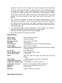
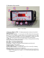
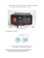
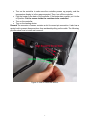
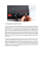
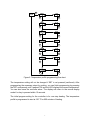
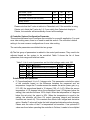
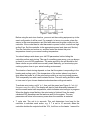
Operation Instruction Manual WS-1500EBPM Precision PID Temperature Controller Version 1.1 Auber Instruments 5755 North Point Parkway, Suite 99 Alpharetta, GA 30022 770-569-8420 www.auberins.com May, 2013 Introduction Thank you for purchasing the Auber WS series temperature controller. We sincerely appreciate your decision and trust that our machine will meet your expectations in both the quality of the result and the value of our product. While we are delighted that you may be anxious to operate the controller for your project, a few minutes of your time reading through this manual will only serve to enhance your experience in the months and years ahead. In particular, we urge you to read through the safety warnings below. Although this plug-and-play controller is very easy to operate, the process involves high temperature and high wattage appliances, and your safety is paramount. SAFETY WARNINGS This controller is designed only to be used with devices that have limited power and their own thermal cutoff protection, such as a thermostat or thermal fuse in case of controller failure. Do not place any objects on the top of controller surface which is used to vent excess heat during its operation. The maximum electric current this controller can handle is 15 Ampere. For 120 volt AC in US and Canada, this limits the heater power to 1800 watts. Due to its compact size and the splash proof design for kitchen applications, the controller has a limited ability to dissipate the heat generated by the internal solid state relay during the initial heat up. The initial full power heat up process cannot be more than 90 minutes. If you system need take longer time to warm up, please read Appendix 1 “Managing the heat generated by the controller” Always place the sensor in the controlled subject when the controller is on. Before turning on the controller, please make sure the sensor is placed inside the container to be controlled. Leaving the sensor outside will form an open loop 1 operation. If the sensor is left outside, the controller will assume the temperature is low even if the controlled subject is already very hot. The controller will provide full power to the heater. It will not only overheat the controller, but also damage your appliance possibly causing a fire. If the sensor is not permanently mounted on the system and is left outside of the system, this could become a potential problem, you should enable the open loop alarm function (see page 11 for details). This controller is designed to control the devices recommended by Auber Instruments only. Using it to control a not recommended device can be dangerous and cause fire. Auber Instruments is not liable for damages caused by misuse of the controller. If you are not sure the controller can be used, please contact Auber Instruments before use. If an abnormal display or noise is observed, turn the controller off, unplug the power cord and contact the manufacturer before using it again. Clean the controller only when it is cool and unplugged. Do not allow children to operate the controller. Specifications Input voltage: Output voltage: Maximum Current: Fuse Size: Control Action: Control Mode Output switching device: 100 to 240 VAC 50 /60 Hz Same as the input. 15A at 120V, 10A at 240V 15A Fast blow. Heating (reversed action) or cooling (direct action) PID, PI, PD, P or On/off Built-in optically isolated solid state relay with zero voltage crossing switching. Sensor type: Pt100 RTD sensor Sensor tip dimensions: 4 mm diameter x 50 mm long. Sensor cable length, 3 ft (915 mm) Alarm: High limit alarm and Open loop alarm with LED and buzzer. Timer Range: 1 to 9999 minutes for each step. 6 steps total. Temperature resolution: 0.1 °C or 0.1 °F Temperature display range: -50.0 to 200.0 °C or -58.0 to 392.0 ° F Temperature accuracy: 0.1°C or 0.2 °F for 0-85 °C (32.0 to 185.0 ° F) Dimension: 6x3x7 inch (155 x80x180 mm) W x H x D. Weight: 2.8 lb (1.3 kg) Warranty: 1 year for controller and sensor Operating Instructions 2 1) Description of the controller. Figure 1. Front Panel (1) Parameter Window (LED) - For displaying temperature values and controller's system parameters. (2) Output status indicator - In normal mode, this LED indicates the heater status. When it is on (lit), the heater is powered. When it is off, the heater power is off. When it is flashing, it means the heater is on and off intermittently to reduce the power output. It should be synchronized with the power light on the cooking device. (3) SET Key - For showing current temperature settings, entering parameters setting mode and confirming various actions taken. (4) “+” Key - To increment displayed value. (5) “-”Key - To decrement displayed value. (6) Time Key - Change the Parameter Window between current timer and temperature values, when pressed. (7) Alarm indicator - Lit when the alarm is on. (8) Timer status indicator - In normal mode, when “(8)” is on and “(9)” is flashing, LED shows the time passed since it’s powered on. (9) Mode indicator - the small “dot” is used to indicate what mode the controller is in. When it is flashing and “(8)” stays on, “(1)” is the time that has elapsed since it’s powered on. 3 When it is flashing “(8)” is off, the controller is in the parameter setting mode. “(1)” is the value can be changed by using (4) and (5) key. Figure 2. Back Panel 2) Connecting the controller Figure 3. Typical connection between the controller and the heating device (in this example, the cooker). The connection of the controller should be done in the following steps. Plug the temperature sensor to the back of the controller. Plug the power cord to the power outlet on the wall. 4 Turn on the controller to make sure the controller powers up properly, and the temperature display is in the range expected. Then, turn off the controller. Plug the heater to the back of the controller. If the heater has a switch, put it in the off position. Put the sensor inside the container to be controlled. Turn on the controller. Turn on the heating device. Remark The connector of sensor contains a slot for correct pin connection. It also has a spring lock to prevent disconnections from accidental pulling on the cable. The following pictures show how to install and remove it. Figure 4. How to install the sensor. 5 Figure 5. How to remove the sensor. 3) Programming the temperature profile. A total of 6 steps can be programmed with this controller. Each step contains the temperature (C0X) and time duration (T0X) setting. They are represented by the symbol C0X and T0X, where “X” is the step number (e.g. Step 4 temperature is represented by C04 and step 4 time is represented by T04). The character, “T”, is displayed as the symbol, “ ”. Time is defined as the duration between the last step and the next step. Please make sure the time is long enough for the heater to heat up the oven. If the time is set too short, the temperature may not be able to reach the current step temperature setting, before it jumps to the next step. The time unit is in minutes with 1 minute resolution. If the recipe only needs one step, you can program the time of the rest of the steps to zero. To program the temperature profile, press SET key once. The display will show C01 for one second and then display the temperature setting for step 1. Use “+” and “-” keys to change the temperature setting. When finished, press the SET again to confirm the change. The display will show T01 for a second and then change to the cook time setting for step 1. Use “+” and “-” keys to change the cook time setting. When finished, press the SET again to confirm the change. The display will go the step 2 setting. The following is the flow chart for the setting procedure. 6 SET 4 sec SET SET SET SET SET SET SET SET SET SET SET SET SET SET Figure 6. Temperature profile programming flow chart. The temperature setting will not be changed if SET is not pressed (confirmed). After programming the necessary steps for cooking, you can finish programming by pressing the SET continuously until it passed T06 and the LED displays the current temperature. You can also leave the controller alone. The display will return to the normal display mode if no key is pressed within 15 seconds. The initial program setting for the controller is for one step heating. The temperature profile is programmed to start at 150 °F for 600 minutes of heating. 7 Table 1. Initial program setting Step # Temp (C) Step # Time (min) C01 60.0 T01 600 C02 0 T02 0 C03 0 T03 0 C04 0 T04 0 C05 0 T05 0 C06 0 T06 0 4) Checking the current step and display the time This is done by pressing the Time Key “(6)” once. The display will show T0X for one second before it displays the time it has been on that step. e.g., it will display t03 for a second, if the controller is in step 3 of the process. When “(8)” is on (lit) and “(9)” is flashing at the same time, LED is in timer mode and shows the actual time passed since the controller was in the current step. Please note that this is not the total time since the controller is powered up. Pressing the Time key again will switch the display to the current temperature. Both “(8)” and “(9)” will be off. 3.4 Tuning the controller This controller is shipped with parameters set for commercial rice cookers. You can try to use these settings for other cooking device also because they are suitable for a typical slow response and balanced system. If you feel the performance is not ideal, you can try to use the recommended PID parameters listed in Table 2. These are the parameters we obtain from tuning the system manually. If your cooker is not listed in the Table 2 of our pre-selected cookers, or the PID parameters we provided are not working for your liking, you can use the auto-tuning function to let the controller to determine the PID parameters automatically. You can also manually tune the PID parameter if you are familiar with PID control technology. To activate the auto-tuning processes or change the P, I and D parameters, please see the next section and Figure 8. Table 2. Recommended PID parameters that can be used as reference point. Symbol P I d Display P I d Commercial Rice cooker, steam table 180 700 40 Commercial Rice cooker, steam table 18 0 150 Home use rice cooker, 54 60 15 17 0 40 Home use rice cooker, wine fermentation. (PD mode) Switch set at Warm position 8 Slow cooker, 7 quart 180 700 40 Slow cooker, 4 quart 54 60 15 Slow cooker, PD mode (low overshoot) 40 0 40 Bradley Smoker 70 600 150 Please note that the P value in table is in Fahrenheit unit. If the controller is using Celsius unit, divide the P value by 1.8. If you switch from Fahrenheit display to Celsius, the controller will automatically convert all the settings. 4) Controller System Configuration Parameter. This section discusses how to configure the controller for a specific application. For most sous vide cooking users, there is no need to read this section. The controller’s default setting is for most common configurations of sous vide cooking. The controller parameters are divided into two groups. A) The first group of parameters is related to the control performance. They need to be adjusted based on the system to be controlled. Table 3 shows the list of these parameters, their range and initial set value. Table 3. List of control parameters and its initial settings under code 166. Symbol P I d AT T Display Description Proportional band (in 0.1 Degree) P Integral constant (second) I Derivative constant (second) d AC Auto-tune Cycle rate (second) C Range 0-600 0-900 0-300 0=off 1=on 1-100 Initial 180 700 40 0 2 Details about each parameter P. Proportional band. It is in 0.1 degree units. This parameter controls the output of the controller based on the difference between the measured and set temperature. Larger the P number means the weaker the action (lower gain). e.g. If P=100, the proportional band is 10 degree (100 x 0.1=10). When the sensor temperature is 10 degrees below the proportional band (10 degrees below the setting), the controller will have 100% output. When the temperature is 5 degrees below the set point, the output is 50%. When the temperature is equal to the setting, the controller will have 0% output (assuming integral and derivative functions are turned off). This constant also affects both integral and derivative action. Smaller P values will make the both integral and derivative action stronger. Please note the value of the P is temperature unit sensitive. If an optimized P value was found when operating the controller in Celsius, it needs to be multiplied 9 by 1.8 when changed to Fahrenheit. On/off mode. If P is set to 0, the control mode will be changed from PID mode to On/off mode. On/off mode should be used for controlling an external relay, a solenoid valve, or a compressor of freezer. You also need to set the hysteresis band (dead band) for the on/off mode. In the on/off mode, Integral and Derivative parameters are not valid. I. Integral time. The unit is in seconds. This parameter controls the output of the controller based on the difference between the measured and set temperature integrated with time. Integral action is used to eliminate temperature offset. Larger numbers mean slower action. e.g. assuming the difference between the measured and set temperature is 2 degree and remain unchanged, the output will increase continuously with time until it reaches 100%. When temperature fluctuates regularly (system oscillating), increase the integral time. Decrease it if the controller is taking too long to eliminate the temperature offset. When I=0, the system becomes a PD controller. For very slow response systems such as those with slow cookers and large commercial rice cookers, setting I = 0 will significantly reduce the temperature overshoot. d. Derivative time. The unit is in seconds. Derivative action contributes the output power based on the rate of temperature change. Derivative action can be used to minimize the temperature overshoot by responding to its rate of change. The larger the number is, the faster the action will be. e.g. when the door of an oven is opened, the temperature will drop at a very high rate. The derivative action changes the controller output based on the rate of change rather than the net amount of change. This will allow the controller to act sooner. It will turn the heater to full power before the temperature drops too much AT, Auto-tuning Every type of cooker has its own unique set of tuning parameters. For the controller to heat with stability, it should have programmed with the tuning parameters for the cooker currently being used. When Should the Controller be Tuned? The Auto-tuning function (it’s often known as self-tuning) can automatically optimize the PID parameters for your chosen cooking system. The auto-tuning function will heat up your cooker then let it cool down. It will repeat this heat/cool cycle several times. Based on the response time of the whole cooking system, the controller will calculate and set the PID parameters for your cooker. 10 Figure 7. Auto-Tuning Before using the auto-tune function, you must set the cooking equipment up in the exact configuration it will be used. For example, to tune a rice cooker, place the sensor in the room temperature pot filled with water and plug the cooker into the controller. If the cooker has its own thermostat or power control, turn both as high as they’ll go. Set the controller to the appropriate power level (see next Section). Turn the controller and cooker on, and then enter the desired set point temperature close to your normal cooking temperature. You should always write down your old PID parameters, before letting the controller perform auto-tuning. This way if something goes wrong, you can always go back to your old PID parameters. The water amount in the pot should be the same volume as you would have normally used. Basically, you must setup your cooking system close to your actual cooking environment. The duration of auto-tuning depends on how fast the system is responding to the heating and cooling cycle. If the temperature of the cooker takes a long time to drop when the heater is off, the auto-tuning could be a very long tuning process. This is especially true with a well insulated cooker. The auto-tuning should be able to tune most of your chosen heaters/cookers/smokers with great results. To activate auto-tuning, set A to 1; then, exit the menu (see Figure 8. Code 166 Parameter setup flow chart). The display will start to flash alternately between A and the current water bath temperature, which indicates auto-tuning is in progress. When the display stops flashing, the auto-tuning is finished. Now, the newly calculated PID parameters are set and are used for the system. The new parameters will store in the memory even when the controller is restarted T, cycle rate. The unit is in seconds. This unit determines how long for the controller to calculate each action. e.g. If T is set to 10 seconds, when the controller decides the output should be 10%, it will turn on the heater 1 second for 11 every 10 seconds. This parameter should set at 2 second for heating with an electric heater. When controlling a solenoid valve or a compressor of refrigerator, the T should be set to 10-20 to reduce the frequency of on/off. To prevent changing critical parameters by accident, an access lock, LCK is used. Special code is needed to open the lock for these parameters. This group of parameters can be accessed by input code 166. Figure 8 is the flow chart that shows how they can be changed. Figure 8. Code 166 Parameter setup flow chart Press and hold SET key for 4 seconds until LED displays “LCK.” Then release the SET key. The display will show “0”. To get into parameters setting mode, you need to key in the pass code. Use “+” and “-” keys to adjust the display to 166 (which is the pass code) and press SET. The LED will show “P” for a second and then its P setting value, Use “+” and “-” keys to change the setting. When finished, press the SET again to confirm the change. The display will show the “I” for a second and its I setting value next, use the same “P” setting procedure to set the I value. When finished, press the SET again to confirm the change. The display will show the “d” for a second and its value next. Use the same “P” setting procedure to set the d value. When finished, press the SET again to confirm the change. The next setting is A, the auto-tune. Use “+” to set the value to 1 12 and press SET will activate the auto-tune. The next setting is the “t” setting, use “-” and “+” to set the cycle time value. This value should remain 2 for most application. After change the PID parameter, the controller needs to be turned off and on again for the best result. B) The second group is about the system configuration and set up. Once they are set, they normally do not need to be changed. This group of parameters can be accessed by input code 155. If you don’t want your system to be altered by other people, do not let others know this code. Table 4 shows the list of the parameters, their range and initial set value. Table 4. List of control parameters and the initial settings under code 155 Symbol SC AL FA OAL Hy COOL Out C-F Display Description SC AL FA OAL HY COOL 00t C-F Range Initial Off set (degree) -20.0 ~+20.0 Alarm Setting -58.0-392.0°F -50.0-200.0°C 180.0 Alarm buzzer 0=off 1=on 0 Open loop alarm 0=off 1=on 0 Hysteresis band 0-100 0.3 0=heat 1=cool 0 1-100 100 °C or °F °C Control mode (heating or cooling) Output power reduction (%) Temperature unit Details about each parameter. SC, calibration offset. The parameter is used to make the input offset to compensate for the error produced by sensor. Each unit is 0.1 degree. e.g. if the temperature displays 2.0 °C in ice water mixture, set SC=-2.0 will make the display to shown 0.0 degree. AL, Alarm temperature in degree. When the temperature passes the alarm set value, the alarm LED and buzzer will be turned on. When the temperature drops to that value, the LED and buzzer will be turned off. The alarm is for high limit alarm only. It will not shut off the out. FA. Alarm buzzer control. When FA=1, the buzzer will be on when the alarm LED is lit. When the FA=0, the buzzer will not be turned on at the alarm temperature. oAL. Open loop alarm. This parameter is for detecting an open loop in the control system. e.g. if the sensor was forgotten to be inserted in the oven, or the sensor is defective, or the heater is defective. When enabled (oAL=1), it will shut off the 13 output if the temperature increased less than 3 °C (5 °F) after the controller was powered up for 5 minutes. The alarm buzzer will be turned on at the same time. The display will flashing OPEN (oPEn). Hy. Hysteresis band (or dead band). This parameter is used for on/off control only. In the on/off heating mode, the heater will be turned off when T = SV, and turned on again when T<SV-Hy. e.g. If SV=100 °C. Hy=3.0 °C, the heater will heat until temperature reaches 100.0 °C. It will be turned on again when temperature drops below 97.0 °C. For the cooling mode, the compressor will be turned off when T=SV. It will be on again when T>SV+Hy. CooL. When Cool=0, the controller is set for heating control (reverse action). When Cool=1, the controller is set for cooling control (direct action). Out, Output power reduction. It is expressed as a percentage value. This function will allow you to control the maximum output power delivered by the heater. For example, if you set Out=50 and your heater is 1000 watts, the output will use 50% of the 1000 watts as the full output. It treats the 1000W heater as a 500W heater. When the PID algorithm determines 50% output value, the actual power output will be 250 watts. This function can be used in two situations. 1) When you have a very powerful heater and are using a very small pot of water to cook at very low temperature, for example, a 1400 watts heater with a one litter (1 qt) pot of water at 130 °F. The heater is too powerful for the small water volume. The moment it is on, it releases too much energy and overshoots the temperature. Although it is still possible to stabilize the temperature with proper PID parameters, it is much easier to control if you limit the maximum output to 25%. Ideally, an optimized temperature control system should consume about 25 % of the heater power at set temperature (steady state), for example, if you found out that only 50 watts of energy is needed to maintain the temperature at 60 °C (141°F), ideally you should use only a 200 watts heater for the job. Too much power will make the system over react too quickly. Too little power will make the system too slow in response. By using the OUt function, you can make the 1400 watts heater to act as a 200 watt heater for stable temperature control. 2) When the cooker consumes more power than controller can handle, for example, if you have a 12A, 120V AC heater and your cooker contains more than 38 liter (10 gallon) of water. It might take more than 90 minutes of full power heating for controller to heat up the pot. Long time of full power operation might cause the controller to over heat. You can set the output to 80%. It will prevent the controller from over heating from staying at full power too long. For details, please see Appendix 1. C-F, Display unit setting. You can set the display either Celsius or Fahrenheit. This group of parameters is accessed by input code 155. Figure 9 is the flow chart that shows how they can be changed. 14 Figure 9. Code 155 Parameter setup flow chart Press and hold SET key for 4 seconds until the Parameter Window displays “LCK”. Release the SET. The display will show “0”. Use “+” and “-” keys to adjust the display to 155 (another pass code) and press SET. Setting the calibration offset. The parameter window will first show “SC “for a second and then its value, Use “+” and “-” keys to change the setting. When finished, press the SET again to confirm the change. For example, if the temperature is 1 °C too high during calibration then use “-” to set the value to -1 to offset value. Setting the output reduction. The parameter window will first show “OUt “for a second and then its value, Use “+” and “-“ keys to change OUt value to your desired limit value and press SET. Setting Celsius (C) or Fahrenheit (F). When SET is pressed, the display will show “CF” and then its value of either “C” or “F”. Press “-” for C or “+” for F. 15 The setting for AL, FA, oAL, Hy, Cool and TK are similar as the rest of parameters. Warranty Auber Instruments warrants this controller to be free from defects in material and workmanship for a period of one (1) year from the date of the original purchase when utilized for normal use, subject to the following conditions, exclusions and exceptions. If your appliance fails to operate properly while in use under normal conditions within the warranty period, return the complete appliance and accessories to Auber Instruments 5755 North Point Parkway, Suite 97 Alpharetta, GA 30022 If the appliance is found by Auber Instruments to be defective in material or workmanship, Auber Instruments will repair or replace it free of charge. A dated proof of purchase may be required. The liability of Auber Instruments is limited solely to the cost of the repair or replacement of the unit at our discretion. This warranty does not cover normal wear of parts and does not apply to any unit that has been tampered with or used for commercial purposes. This limited warranty does not cover damage caused by misuse, abuse, negligent handling or damage due to faulty packaging or mishandling in transit. This warranty does not cover damage or defects caused by or resulting from damages from shipping or repairs, service or alterations to the product or any of its parts which have been performed by a repairperson or facility not authorized by Auber Instruments. This warranty is available to the original purchaser of the unit and excludes all other legal and/or conventional warranties. The responsibility of Auber Instruments, if any, is limited to the specific obligations expressly assumed by it under the terms of the limited warranty. In no event is Auber Instruments liable for incidental or consequential damages of any nature whatsoever. Some states/provinces do not permit the exclusion or limitation of incidental or consequential damages and therefore the above may not apply to you. This warranty gives you specific legal rights and you may also have other rights which vary from state to state or province to province. *Important: Carefully pack item(s) to avoid damage in shipping. Be sure to include proof of purchase date and to attach tag to item before packing with your name, complete address and phone number with a note giving purchase information, model number and what you believe is the problem with item. We recommend you insure the package (as damage in shipping is not covered by your warranty). Mark the outside of your package 16 “ATTENTION CUSTOMER SERVICE”. We are constantly striving to improve our products and therefore the specifications contained herein are subject to change without notice. 17 Appendix 1 Managing the heat generated by the controller The heat dissipation of the controller is directly related to the electric current drawing power of the heater. If your cooker consumes less than 10 ampere of current or your pot is less than 5 gal (19 liters), you do not need to worry about the heat generated by the controller. Sometimes, the AC current requirement might not be marked on the cooking appliance. To find out how much current it will draw, divide the power (in wattage) by the line voltage, for example, an 1800 watts 120V heater will draw 15A. A 2000 watts 240V heater will draw 8.3 Ampere. Why the heat becomes an issue? The solid state relay (SSR) used in the controller is a critical component for the precision temperature control. With the SSR, the power can be switched at high speeds with no noise and no life time limitation. Compared with electromechanical relays, however, SSRs have one drawback. They generate heat when passing the current. SSR’s are made of semiconductors that have a limited conductance. When passing current, the heat will be produced from the resistance. Each ampere of current will produce about 1.3 watts of heat. When 12 Amp is passing through the controller, 16 watt of heat is produced in the controller. As more heat is produced, the temperature inside the controller will rise. If it reaches to higher than 70 °C, it can shorten the life or even damage some other components in the controller. The temperature inside of the controller depends on the amplitude of the current, how long the controller needs to run at full power and the ambient temperature. The heat is only an issue during the start of the heating when the heater is running at full power. Once the temperature is close to the set point, the controller will probably need less than 50% of the power to maintain the temperature. Since the heat is directly related to the current passing the controller, the heat produced at steady state will be insignificant and can be ignored. When the heat becomes an issue? This controller can run at 10A continuously without worry of the temperature of the controller. At 12A, the temperature of the controller will increase with time. The bottom of the controller where the heat sink is located can rise by 63 °F (35 °C) from ambient if running at full power continuously for 90 minutes. For this reason we don’t recommend running the controller at full power for more than 90 minutes. For 120 VAC, 15 A for 90 18 minutes will provide enough energy to heat 10 gallons (38 liters) of water up by 108°F (60 °C). If your have a pot that is bigger than 10 gallons and the heater is drawing 15 A, and you need to raise the temperature by 108 °F, you better use one of the methods mentioned below to reduce the heat in the controller. Otherwise, you might damage the controller. Please note that when the ambient temperature is hot, as it often is the case in some commercial kitchens, the temperature of the controller will get hotter. This is because the heat dissipation is mostly determined by the temperature gradient (the temperature difference between the ambient and the controller) instead of absolute temperature of the controller itself. If the controller reaches 50 °C when the ambient is at 20 °C, it will reach 70 °C when the ambient is at 40 °C. Solutions to reduce the heat stress on the controller. 1) Use hot water. If you fill the pot with hot water that has a temperature close to the set temperature, the heat dissipation of the controller is not an issue. As we have mentioned, once the temperature is close to the set point temperature, the controller starts to pulse (PWM) the power. The effective current is much lower, making heat not an issue. 2) Limit maximum output power. If you set output reduction parameter to 80%, then, a 15A heater will become a 12A heater. It will take 25% longer time to heat up the pot, but the controller will not over heat. In addition to these solutions, following information will also help you to manage the heat. Place the controller in the right place. The SSR of Auber WS series controller is mounted in the bottom of chassis. The chassis is made of 3 mm thick aluminum for good heat dissipation. Do not cover the controller with any insulation. If you are running at 15 A with a large pot, placing the controller in a well ventilated area and tilting the instrument up with its front legs will help remove the heat more efficiently. However, the tilted position may result in water collected at the back frame. Although the controller is splash proof, you should avoid water to be dripped on the controller when you open the lid of the cooker. Increase the P value. This can only provide limited help for reducing the heat. P is the proportional band. P=200 means the proportional band is 20.0 degrees. When the temperature is raised to less than 20 degree from the set point temperature, the controller will start to reduce the power sooner. But if the integration time is set to very short, the controller might start to run at full power again soon. 19