1
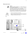
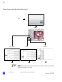
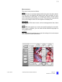
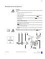
OPMI® Pentero®
Software Release 2.2
Brief instructions
G-30-1702-en
Issue2.0
Printed on 17. 03. 2008
2
Contents
Key to symbols
Page 3
Powering up and positioning the system
Page 4
Positioning the microscope
Page 5
Attaching sterile drapes
Page 6
Balancing the system
Page 7
Central user interface (touchscreen)
Page 8
Menu structure
Page 9
Illumination
Page 10
Lamp change
Changing the lamp module
Page 11
Page 11
Adjusting the position of the handgrips
Page 12
Configuring the handgrips
Page 13
Configuring the foot control panel
Page 14
Mounting the tube and eyepieces
Page 15
Attaching documentation / coobservation equipment
Page 16
Adjusting the tubes and eyepieces
Page 17
Setting the eyepieces (compensation for ametropia)
Page 18
Setting the adjustment speeds of focus and zoom
Page 19
OR layout drawings
Page 20
Exporting patient data to CD/DVD/USB/DICOM
Page 22
Connecting an external monitor
Page 24
What to do in an emergency - brief instructions
Page 26
Lamp change during power failure
Failure of the zoom function
Failure of the focusing function
Failure of the magnetic brakes
Failure of the touchscreen
Failure of the line voltage
Error messages in the data injection system and on the touchscreen
Failure of all control functions (Emergency mode)
Blocking of individual magnetic brakes
G-30-1702-en
OPMI® Pentero® Software Release 2.2
Page 28
Page 30
Page 31
Page 32
Page 32
Page 32
Page 33
Page 34
Page 35
Issue 2.0
Printed on 17. 03. 2008
3
Caution:
These brief instructions are only an excerpt from the complete user
manual. They cannot replace the detailed description provided in
the user manual.
Therefore, make yourself thoroughly familiar with the comments
and warning notes included in the complete user manual G-30-1458.
Key to symbols
Different symbols used in this manual draw your attention to safety aspects and useful tips. These symbols are explained in the following.
Warning!
The warning triangle indicates potential sources of danger which may
constitute a risk of injury for the user or a health hazard.
Caution:
The square indicates situations which may lead to malfunction, defects,
collision or damage of the system.
Note:
The hand indicates hints on the use of the system or other tips for the
user.
Read the user manual!
OPMI® and Pentero® are registered trademarks of Carl Zeiss Surgical
GmbH.
AutoDrape™, Superlux, FlexiTrack™ and MultiVision™ are trademarks of Carl Zeiss Surgical GmbH.
G-30-1702-en
OPMI® Pentero® Software Release 2.2
Issue 2.0
Printed on 17. 03. 2008
4
Switching on the system
Warning!
– The correct use of the system is absolutely vital for safe operation.
Therefore, please thoroughly familiarize yourself with the content of
user manual G-30-1458 before starting up the system.
–
Before starting, make sure to read the chapters "Safety" and "Preparations for use" of the user manual!
On / Off
ro
nte
Pe
MI
OP
3
2
1
G-30-1702-en
OPMI® Pentero® Software Release 2.2
Issue 2.0
Printed on 17. 03. 2008
5
Positioning the microscope
Warning!
For safety reasons, the system must only be used when correctly balanced.
Before starting, make sure to read the chapter "Preparations for use" of
the user manual!
•
Press the brake release buttons (AB) to unlock all magnetic brakes.
Keep the brake release buttons (AB) pressed and move the ceiling
mount into the working position required using the handgrips. When
you let go of the brake release buttons (AB), all magnetic brakes are
locked.
AB
G-30-1458
G-30-1458
G-30-1702-en
OPMI® Pentero® Software Release 2.2
Issue 2.0
Printed on 17. 03. 2008
6
Positioning the system at the operating table
The stand is provided with a handle which allows the reliable and easy
guidance of the system during relocation. Please only use this handle for
this purpose.
The stand base is equipped with the new FlexiTrak technology which
makes it considerably easier for you to move and position the system in
the OR. Two additional pedals on the base allow you to conveniently select the required condition of the stand:
1
2
–
None of the pedals has been pressed:
Exact and sensitive positioning in the OR and at the operating table in
all directions with a minimum of effort.
–
Right-hand pedal (2) is pressed down hard until it snaps in:
Reliable and precise straight-ahead movement, also over low thresholds (elevator). Press this pedal until it snaps in to set the two front
casters for straight-ahead travel. The other casters remain steerable.
When you slightly press pedal (1), all four casters will be steerable
again.
–
Pressing left-hand pedal (1) to the stop will lock the stand base in position, preventing it from inadvertently rolling away. After the system
has been finally positioned at the operating table, you should step on
this pedal.
3
4
Possible positions for cranial procedures
Possible positions for face-to-face procedures (spine)
5
6
Surgeon
Assistant
Note:
The system allows overhead positioning and can therefore be placed in
any position behind the surgeon or assistant.
G-30-1702-en
OPMI® Pentero® Software Release 2.2
Issue 2.0
Printed on 17. 03. 2008
7
5
3
6
5
6
4
G-30-1702-en
OPMI® Pentero® Software Release 2.2
Issue 2.0
Printed on 17. 03. 2008
8
Attaching sterile drapes
Caution:
When attaching the drape, please ensure that there is sufficient space for
the tilt and rotation movements of the surgical microscope.
Effective range
of drape vacuum system
1
Sterile area
Non-sterile
area
DRAPE
Hier luftdicht abschließen
Make airtight here
Fermer hermétiquement ici
Cerrar hermélicamente aqui
MENU
PHOTO
FOCUS
ZOOM
LIGHT
359 mm
5.9x
33%
FREEZE
2
DRAPE
AUTOBALANCE
REC START
PAT-FILES
VOICE CTRL
USER
DICTATION
TELEPHONE
CONFIG
FULL SCREEN
G-30-1702-en
OPMI® Pentero® Software Release 2.2
FOCUS
SPEED
ZOOM
SPEED
LIGHT
INTENSITY
Issue 2.0
Printed on 17. 03. 2008
9
Balancing the system
Warning!
Make sure to observe the instructions in the chapter "Balancing the
system" of user manual G-30-1458.
For safety reasons, the system must only be used when correctly balanced. Despite the autobalance function, it may happen in exceptional
cases that the surgical microscope is not correctly balanced.
With an incorrectly balanced system, brake release may lead to uncontrolled movements of the suspension system. For this reason, the balancing procedure and the subsequent test must not be performed above
the patient and only at a safe distance from other persons and devices.
SB
AB
•
Hold the microscope tightly at both handgrips.
•
Unlock the magnetic brakes (AB) and swing out the microscope until
indicator (1) is centered in the blue area (2). Then you can perform the
"Autobalance Complete System" procedure.
PHOTO
MENU
Autobalance
Autobalance Complete System
START
Autobalance Microscope
START
Drape Compensation
START
FREEZE
30. 01. 04
User:
17:56
DRAPE
XXXXXXXX
Patient:
XXXXXXX
Recorder Capacity:
AUTOBALANCE
STOP
Int:.......% Ext:.........%
REC START
1
PAT-FILES
VOICE CTRL
USER
2
DICTATION
TELEPHONE
CONFIG
Fine adjustment mouth switch
-
-3
+
FULL SCREEN
CLOSE
G-30-1458
Fine adjustment for mouth switch
G-30-1702-en
OPMI® Pentero® Software Release 2.2
Issue 2.0
Printed on 17. 03. 2008
10
Central user interface (touchscreen)
Start
MENU
PAT-FILES
USER
CONFIG
Note:
For detailed information on the submenus and their configuration, please
see user manual G-30-1458.
G-30-1702-en
OPMI® Pentero® Software Release 2.2
Issue 2.0
Printed on 17. 03. 2008
11
Menu structure
The menu is structured as follows:
MENU
The main menu is constantly displayed after the system has been started.
You can use it for triggering still camera and video recording, for automatic balancing of the system, for activating the drape vacuum system
and for switching the illumination on and off. The full-screen mode permits
you to view images or the live video signal in full display size.
PAT-FILES
Use the Patient Files menu to save, edit and manage patient data, videos
and images.
USER
The USER menu permits you to save user-specific settings for several different users. In addition, you can select several different languages for
user guidance here.
CONFIG
The CONFIG menu permits you to enter the settings for the microscope
and suspension system parameters.
PHOTO
MENU
FOCUS
ZOOM
359 mm
5.9x
LIGHT
33%
FREEZE
30. 01. 04
17:56
User:
45%
DRAPE
XXXXXXXX
Patient:
XXXXXXX
Recorder Capacity:
AUTOBALANCE
Int:.......% Ext:.........%
REC START
PAT-FILES
VOICE CTRL
USER
CONFIG
DICTATION
TELEPHONE
FOCUS
FULL SCREEN
G-30-1702-en
359 mm
OPMI® Pentero® Software Release 2.2
ZOOM
SPEED
LIGHT
INTENSITY
Issue 2.0
Printed on 17. 03. 2008
12
Illumination
Warning!
Before starting, make sure to read the notes on "Risk of phototoxic injuries
caused by high illumination intensity" in chapter "Safety"!
Setting the illumination on the touchscreen
PHOTO
MENU
FOCUS
ZOOM
359 mm
5.9x
LIGHT
ON
LIGHT
ON/OFF
FREEZE
17:56
30. 01. 04
User:
3
DRAPE
XXXXXXXX
33%
Patient:
XXXXXXX
AUTOBALANCE
Recorder Capacity:
Int:.......% Ext:.........%
REC START
PAT-FILES
VOICE CRTL
USER
CONFIG
2
DICTATION
TELEPHONE
FULL SCREEN
FOCUS
SPEED
ZOOM
SPEED
LIGHT
INTENSITY
1
Setting the illumination in the "Light" configuration menu
LIGHT
MENU
OPMI
Light
On
Brightness
Speed
Light Intensity
Control
Low
On
Medium
Off
LIGHT
30. 12. 04 17:56
User:
XXXXXXXX
Patient:
XXXXXXX
Recorder Capacity:
Int:.......% Ext:.........%
Off
STAND
AUDIO/VIDEO
High
Threshold Value
Light Warning
25%
FLUORESCENCE
PAT-FILES
MULTIVISION
G-30-1458
USER
CONFIG
G-30-1702-en
Intensity
Start Value
24%
Remaining
lamp lifetime
200h
Lamp 2
in use
Yes
TELEPHONE
SYSTEM INFO
OPMI® Pentero® Software Release 2.2
Issue 2.0
Printed on 17. 03. 2008
13
Lamp change
Open the cover. The lever for changing the lamp moves out.
Pull out the lever as far as it will go without using force.
If the lever has not been properly pulled, the lamp will not be changed. Pull
the lever again to make the lamp snap into position.
Close the cover again.
3
2
G-30-1458
1
Changing the lamp module
6
defective
lamp
3
1
5
2
4
G-30-1702-en
OPMI® Pentero® Software Release 2.2
Issue 2.0
Printed on 17. 03. 2008
14
Adjusting the position of the handgrips
You can adjust the position of the handgrips to meet your specific needs.
•
Open locking lever (1) and adjust the mounting bar or the handgrip
only to the position required.
•
Choose a position of the handgrips which is most convenient for the
surgical procedure to be performed. Make sure that there is enough
room between the handgrips and the accessories mounted on the microscope.
•
Firmly re-tighten locking lever (1).
Note:
The handgrips including the locking levers can be rotated through approx.
180°.
1
1
G-30-1702-en
OPMI® Pentero® Software Release 2.2
Issue 2.0
Printed on 17. 03. 2008
15
Configuring the handgrips
1
Focus +
Focus -
Zoom +
C
You can trigger the functions of the surgical microscope using the buttons
on the handgrips or on a foot control panel. Programmable buttons can be
configured for the requirements of each user.
Both handgrips are identical. In the basic setting, joystick (1) can be used
for motorized fine movement in the XY directions.
You can configure both handgrips with the same functions (CONFIG), or
you can configure different functions in the right and left handgrip.
The CONFIG menu / STAND / HANDGRIPS permits you to select the
functions to be assigned to programmable buttons A, B, D or E. The
rocker switches for Zoom and Focus can be reconfigured by the user.
Briefly press button (C) on the touchscreen.
The display and functions will be swapped.
Zoom -
A
B
1
FOCUS
ZOOM
D
E
HANDGRIP
FOOT
SWITCH
LEFT
MENU
31.12.
04 23:56
User:
XXXXXXXX
Patient:
: Ext:.........%
LIGHT
Photo
Autofocus
RIGHT
Autofocus
Photo
Focus +
Zoom +
Aux
MultiVision
AUDIO/VIDEO
Focus -
Zoom -
Light +
Light -
FLUORESCENCE
2
Fluorescence
Light Intensity
No function
MULTIVISION
CONFIG
Videorec
STAND
PAT-FILES
USER
BRAKES
MOTORS XY
OPMI
TELEPHONE
SYSTEM INFO
Factory settings
CONFIG
RESET
Configuring the handgrip buttons
Press CONFIG to configure both handgrips. For separate programming
of the left or right handgrip, press the LEFT or RIGHT button respectively.
The buttons are only displayed if the CONFIG button has been pressed.
Press the button (A, B, D, E) to which you would like to assign a different
function.Then press the relevant function in selection menu (2) to assign
it to the selected button. The labeling of the button is changed and indicates the new function.
Press the RESET button to restore the factory settings.
Note: The joystick on the right handgrip is used for special functions in optional applications.
G-30-1458
G-30-1702-en
OPMI® Pentero® Software Release 2.2
Issue 2.0
Printed on 17. 03. 2008
16
Configuring the foot control panel
Zoom -
Fokus -
Zoom +
Fokus +
You can trigger the functions of the surgical microscope using the buttons on the handgrips or on a foot control panel. Programmable buttons can be configured for the requirements of each user.
The joystick on the foot control panel permits motorized fine movement of the microscope in the XY directions.
The rocker switches for Zoom and Focus can be reconfigured by the
user. Briefly press button (E) on the touchscreen. The display and
functions will be swapped.
E
Fokus +
Fokus -
Zoom +
Zoom -
HANDGRIPS
MENU
17:56
30. 12.
User:
XXXXXXXX
Patient:
XXXXXXX
OPMI
LIGHT
STAND
MOTORS XY
FOOT SWITCH
ROCKER
SWITCH
BRAKES
FOOT
SWITCH
CONTROL
PANEL
MultiVision
Autofocus
Videorec
A
B
C
D
Photo
AUDIO/VIDEO
Zoom -
FLUORESCENCE
Zoom +
Focus
Light -
Light +
Focus -
E
PAT-FILES
MULTIVISION
USER
CONFIG
TELEPHONE
SYSTEM INFO
Autofocus
MultiVision
Videorec
Fluorescence
Photo
Light Intensity
Aux
No function
Factory settings
RESET
1
Configuring the programmable buttons A, B, C, D
G-30-1702-en
•
Press the button (A, B, C, D) to which you would like to assign a different function.
•
Then press the relevant function in selection menu (1) to assign it to
the selected button. The labeling of the button is changed and indicates the new function.
•
Press the RESET button to restore the factory settings.
OPMI® Pentero® Software Release 2.2
Issue 2.0
Printed on 17. 03. 2008
17
Mounting the tube and eyepieces
Warning!
Change the modules and accessories before surgery and without the patient!
•
Loosen securing screw (8) by a few turns.
•
Remove cover (4).
•
Attach spine adapter (3) to the microscope body and firmly tighten securing screw (8).
•
Attach binocular tube (2) to spine adapter (3) and firmly tighten securing screw (7).
•
Insert widefield eyepieces (1) as far as they will go in the mounts provided on the binocular tube.
•
Attach binocular coobservation tube (5) to the microscope body and
firmly tighten securing screw (9).
•
Insert widefield eyepieces (6) as far as they will go in the mounts provided on the binocular tube.
•
Before starting up the system, remove protective cap (10) from the objective.
Warning! Check that all modules are securely seated. Firmly tighten securing screws (8) and (9)! Balance the surgical microscope, page 9.
G-30-1458
1
2
3
7
G-30-1702-en
OPMI® Pentero® Software Release 2.2
4
2
5 5
8
10
6
9
Issue 2.0
Printed on 17. 03. 2008
18
Attaching documentation / coobservation equipment
•
Loosen knurled ring (1).
•
Remove dust cover (2) and keep it in a safe place.
•
Insert accessory module (3) in the mount of the image exit port and
carefully turn it until the guide projections fit into the grooves. Push the
accessory module into the mount as far as it will go.
•
Screw knurled ring (1) onto accessory module (3) and firmly tighten it.
The type of coobservation (lateral image exit ports: left/right, or opposite
image exit ports: face to face) can be configured at the touchscreen
(CONFIG/OPMI/TUBE).
The sliding mirror has two positions:
Left/Right: The light is directed to the lateral image exit ports.
Face to Face: The light is directed to the tube mount at the back.
The position of the sliding mirror can also be switched manually using
knob (4).
Warning! Check that all modules are securely seated. Firmly tighten securing screws (8) and (9)! Balance the surgical microscope, page 9.
G-30-1458
4
3
G-30-1702-en
2
1
OPMI® Pentero® Software Release 2.2
2
3
Issue 2.0
Printed on 17. 03. 2008
19
Adjusting the tubes and eyepieces
1
Adjusting the interpupillary distance
This is done by pressing the two eyepieces together or pulling them
apart. The correct position has been reached when the two eyepiece
images merge into one.
2
PD adjustment knob
The correct position has been reached when the two eyepiece images
merge into one.
3
Eyecup
Adjust the eyecups in such a way that the entire field of view can be
seen.
–
Viewing with eyeglasses:
Screw in the eyecups all the way.
–
Viewing without eyeglass- Adapt the eyecups to the viewer's
es:
field of view by screwing them outward. The three white marking rings
facilitate the adjustment.
4
Diopter setting ring
The eyepieces provide compensation for ametropia. Eyeglass
wearers using their glasses during work should set the diopter setting
ring to 0. Turn the ring until the optimum setting has been achieved
(see following page).
5
Diopter scale
For reading off the prescription set.
1
3
G-30-1702-en
4 5
2
3
OPMI® Pentero® Software Release 2.2
4
5
Issue 2.0
Printed on 17. 03. 2008
20
Setting the eyepieces (compensation for ametropia)
Bring the surgical microscope into its starting position within the focusing range. Adjust the minimum magnification on the surgical
microscope. Bring the surgical microscope into the position required. Adjust your interpupillary distance on the binocular tube. Adjust
your prescription on the eyepieces. Please note that instrument myopia can occur.
Emmetropes
adjust the diopter scale to 0 diopter
(D).
Ametropes (who do not know their prescription and perform surgery without wearing their glasses)
Eyeglass wearers
(who perform surgery wearing their
eyeglasses) adjust the diopter scale
to 0 diopter (D).
Adjust both eyepieces on the main microscope to +8 D.
Adjust both eyepieces on the assistant's microscope to +8 D (if applicable).
Ametropes
(who know their prescription and
perform surgery without wearing
their glasses) adjust the diopter scale to their prescription.
Eyepieces without reticle:
Eyepieces with reticle:
Remove the binocular tube and the
eyepieces from the microscope
body and point them at a distant object*), i.e. use them like a pair of binoculars. The image of the object is
still unsharp.
Turn the diopter scale on the eyepiece
slowly clockwise until the reticle is
imaged sharply.
Turn the diopter scale of one eyepiece slowly clockwise until the object is imaged sharply. If necessary,
repeat this procedure three times
and take the average of the readings. Adjust the second eyepiece
in the same manner.
Focus the surgical microscope on the
object. The reticle and the object must
be in focus at the same time.
Mount the tube and eyepieces on
the microscope body and tighten
the securing screw firmly.
Adjust the second eyepiece in the same
manner until the object is seen sharply.
Adjust the eyecups in such a way that you can see the full field of view. Adjust maximum magnification on the surgical microscope
and focus on the object. Adjust the working magnification required. When the magnification is changed, the focal plane is retained,
but the depth of field changes.
Note: Enter the prescription values in the relevant user profile.
*) Warning! Never use the sun as the distant object!
G-30-1702-en
OPMI® Pentero® Software Release 2.2
Issue 2.0
Printed on 17. 03. 2008
21
Setting the adjustment speeds of focus and zoom
Press the focus or zoom button in the main menu. Use the displayed
slider to set the focus or zoom speed as required.
These settings can also be performed in the configuration menu. Press
CONFIG/OPMI and select the Focus or Zoom tab. Use the slider to set
the focus or zoom speed as required.
In the main menu:
FOCUS
359 mm
MENU
ZOOM
5.9x
FOCUS
359 mm
MENU
ZOOM
5.9x
50%
50%
4
2
FOCUS
SPEED
FOCUS
SPEED
ZOOM
SPEED
3
1
In the configuration menu:
2
FOCUS
OPMI
MENU
LIGHT
30. 12. 04 17:56
User:
XXXXXXXX
Patient:
XXXXXXX
Autofocus
Automatic
4
DIAPHRAGM
ZOOM
Micromanipulator
Focus Stop
FOCUS
TUBE
Focusing Aid
Laser Spots
On
On
On
Off
Off
Off
MENU
Focus
Speed
Focus
Start Value
50%
300 mm
FLUORESCENCE
Focus
Zoom Link
30. 12. 04 17:56
User:
XXXXXXXX
Patient:
XXXXXXX
CONFIG
G-30-1702-en
TUBE
STAND
AUDIO/VIDEO
Gamma
Start
Speed
50%
1.2
FLUORESCENCE
PAT-FILES
MULTIVISION
1
DIAPHRAGM
OPMI
On
Off
PAT-FILES
USER
ZOOM
LIGHT
STAND
AUDIO/VIDEO
ZOOM
SPEED
MULTIVISION
USER
TELEPHONE
SYSTEM INFO
3
CONFIG
OPMI® Pentero® Software Release 2.2
TELEPHONE
SYSTEM INFO
5
Issue 2.0
Printed on 17. 03. 2008
22
Exporting patient data to CD/DVD/USB stick/DICOM
•
Open PAT-FILES menu (1).
•
Open "LIST" tab (2).
•
Activate the required patient in list (3).
•
Open the image folder of the patient (4).
USB
•
Select the images you want to export and mark them by pressing Mark
button (5).
DVD
•
Press "SAVE" button (6).
•
Select the storage medium to be used in the SAVE menu: CD/DVD,
USB STICK or DICOM (7).
Note:
The display shows the number of images selected for export.
•
Insert a new, blank data carrier in the CD/DVD drive or plug a USB
stick into the port on the touchscreen (8).
9
Export in the DICOM format
See DICOM option
10 Save images anonymously
Enables anonymous saving of the selected images.
•
Press "COPY" (11) to export the images.
The data export process is indicated by a progress bar.
•
Press the button on the CD/DVD drive to remove the CD/DVD.
In the local image folder, exported images are marked by the storage
symbol
.
Note:
The system is not intended for the permanent saving of data. You can use
CDs/DVDs, a USB stick, an external hard drive or a hospital server
(DICOM option) for data backup. All users are responsible for saving their
own data.
G-30-1702-en
OPMI® Pentero® Software Release 2.2
Issue 2.0
Printed on 17. 03. 2008
23
2
LIST
MENU
PATIENT
DELETE
30. 12. 04 17:56
User:
XXXXXXXX
Patient:
Benninger Ralph
Recorder Capacity:
Int:.......% Ext:.........%
1
ADD
EDIT
IMAGES
Bachmann E.
VIDEOCLIPS
3
Benninger Ralph
Busch W.
PAT-FILES
LOAD
USER
SAVE
CONFIG
SORT
BACK
MENU
4
12 X
4X
1X
INDEX
PATIENT
IMAGES
30. 12. 04 17:56
User:
XXXXXXXX
Patient:
Benninger Ralph
Recorder Capacity:
Int:.......% Ext:.........%
VIDEOCLIPS
PAT-FILES
LOAD
USER
BACK
SAVE
NEXT
SELECT ALL
EDIT
Delete
FULL
CONFIG
Mark
6
5
7
CD/DVD
MENU
9
30. 12. 04 17:56
User:
XXXXXXXX
Patient:
Benninger Ralph
Recorder Capacity:
Int:.......% Ext:.........%
USB STICK
DICOM
PATIENT
3
0
0
8
IMAGES
VIDEOCLIPS
Export in
DICOM format
On
Off
Archive images
anonymously
On
Off
PAT-FILES
10
LOAD
USER
SAVE
Data export
!
CONFIG
Files are being transferred
This process may take a few minutes.
COPY
11
G-30-1702-en
CANCEL
OPMI® Pentero® Software Release 2.2
Issue 2.0
Printed on 17. 03. 2008
24
Connecting an external monitor
Caution:
Only connect the monitor to a wall outlet which is provided with a properly
connected protective ground conductor.
1
Video signal output port BNC (VBS)
for connecting an external monitor.
Suitable for devices capable of processing VBS signals, or if video signals have to be transmitted over relatively long distances.
2
Video signal output port for an external monitor (Y/C)
for connecting a further external monitor.
Y/C provides higher video image quality than VBS.
The two ports on the control panel are independent of each other and can
be used as required.
Note:
Monitors connected to the video signal output ports (BNC or Y/C) display
the live image of the camera.
G-30-1702-en
OPMI® Pentero® Software Release 2.2
Issue 2.0
Printed on 17. 03. 2008
25
1
2
G-30-1702-en
BNC
Y/C
OPMI® Pentero® Software Release 2.2
Issue 2.0
Printed on 17. 03. 2008
26
What to do in an emergency
1
Failure of illumination - changing the xenon lamp:
•
2
Open flap (1)
• Change the xenon lamp by pulling grip (8)
Failure of the zoom function:
page 28
•
3
Manually adjust the magnification using zoom knob
(2). If the motorized zoom function becomes active of
its own accord (e.g. travels to the stop), set emergency
switch (7) to the emergency mode (position 2).
page 30
Failure of the focusing function:
•
4
Manually adjust the working distance using focusing
knob (3). If the motorized focusing function becomes
active of its own accord (e.g. travels to the stop), set
the emergency switch to the emergency mode (position 2)
page 31
Some of the magnetic brakes are blocked:
•
Switch off power switch (4). As soon as the blue
screen appears (approx. 10 sec), switch the system
back on.
The OPMI functions (zoom, focus, light and magnetic
brakes) are available again after approx. 15 seconds.
The computer and touchscreen, however, are disabled.
If the magnetic brakes are still blocked:
•
5
Hold the microscope on its body (not on the handgrips)
and position it manually by overcoming the braking effect.
page 35
Failure of the touchscreen:
•
6
Do not under any circumstances touch the touchscreen, since this can result in changes to settings and
parameters. Zoom, focus, illumination and brakes can
still be operated.
page 32
Error messages in the data injection system:
•
G-30-1702-en
System errors are displayed in the microscope's integrated data injection system. You can delete these
messages by acknowledgement using the joystick of
the right handgrip (pushbutton) or the touchscreen.
page 32
OPMI® Pentero® Software Release 2.2
Issue 2.0
Printed on 17. 03. 2008
27
7
Failure of control functions:
•
Set emergency switch (7) to the emergency mode (position 2). Zoom and focus must then be operated manually (2, 3).
•
Hold the microscope on its body (not on the handgrips)
and position it manually by overcoming the braking effect.
page 34
6
3
2
5
8
1
7
4
G-30-1702-en
OPMI® Pentero® Software Release 2.2
Issue 2.0
Printed on 17. 03. 2008
28
Emergency instructions - overview
Illumination failure - changing the xenon lamp
•
Open flap (3) as far as it will go.
Lever (1) for changing the lamp moves out.
•
Pull out lever (1) as far as it will go, without using too much force.
If you do not properly pull the lever, the lamp is not changed. Pull the
lever again to make the lamp snap in.
•
Close the flap again.
•
Order a new xenon lamp. Cat. No. (2) is shown on the lamp module.
Note:
– Only change the used lamp if replacement is available on site.
Always operate the illumination system with both xenon lamps. If one
of the lamp fails, switch to the second lamp. Leave the failed lamp in
the lamp housing until it is replaced by a new lamp.
–
G-30-1702-en
Every time you switch on the system, it indicates that you are using
the backup lamp, until the used lamp is replaced.
OPMI® Pentero® Software Release 2.2
Issue 2.0
Printed on 17. 03. 2008
29
1
2
3
G-30-1702-en
OPMI® Pentero® Software Release 2.2
Issue 2.0
Printed on 17. 03. 2008
30
Failure of the zoom function
Failure of the zoom function while all other functions of the suspension system work correctly
•
Adjust the magnification manually using zoom knob (1).
Failure of the zoom drive
In the event of a failure of the zoom drive (e.g. zoom drive moves constantly into an end position):
•
Set the mode selector switch on the connection panel to emergency
operation. This ensures that the light source continues to be operative
without any restrictions.
•
Adjust the magnification manually using zoom knob (1).
•
Continue surgery by manually operating the suspension system and
the surgical microscope by overcoming the locking effect of the
brakes.
1
G-30-1702-en
OPMI® Pentero® Software Release 2.2
Issue 2.0
Printed on 17. 03. 2008
31
Failure of the focusing function
Failure of the focusing function while all other functions of the suspension system work correctly
•
Adjust the working distance manually using focusing knob (1).
Failure of the focusing drive
In the event of a malfunction of the focusing drive (e.g. focusing drive
moves constantly into an end position):
•
Set the mode selector switch on the connection panel to emergency
operation. This ensures that the light source continues to be operative
without any restrictions.
•
Adjust the working distance manually using focusing knob (1).
•
Continue surgery by manually operating the suspension system and
the surgical microscope by overcoming the locking effect of the
brakes.
1
G-30-1702-en
OPMI® Pentero® Software Release 2.2
Issue 2.0
Printed on 17. 03. 2008
32
Failure of the magnetic brakes
If the magnetic brakes fail (magnetic brakes are locked), you can manually move the axes of the stand by overcoming the locking effect of the
brakes.
Touchscreen failure
Warning!
Do not under any circumstances touch the touchscreen. There is a possibility that only the illumination of the display has failed. In this case, you
would inadvertently call menus or change settings when touching the
screen.
Note:
If the touchscreen no longer responds to your entries, you can still continue to operate the OPMI Pentero with the current settings.
To restore the touchscreen function, proceed as follows:
•
Switch the suspension system off and back on again after a short time
(approx. 2 minutes).
After power-up, the system automatically goes into the standard operating mode after it has completed a self-test (approx. 30 seconds).
•
Check all functions of the surgical microscope and suspension system.
You can continue surgery in the standard operating mode.
Failure of the line voltage
In the event of power failure, the uninterruptible power supply (UPS) automatically starts to operate. It ensures for a short period of time that no
data will be lost.
Note:
The UPS does not power the light source and microscope functions.
G-30-1702-en
OPMI® Pentero® Software Release 2.2
Issue 2.0
Printed on 17. 03. 2008
33
If no power is available over a prolonged period of time, the system is shut
down. As soon as line power is back, the user is informed accordingly
(Power OK) and all subsystems are re-initialized.
In the event of power failure (magnetic brakes are locked), you can manually position the arm of the suspension system with the microscope by
overcoming the locking effect of the brakes.
Error messages in the data injection system and on the touchscreen
1
G-30-1702-en
Major system errors are displayed in the microscope's integrated data injection system. You can delete these messages by acknowledgement
using joystick (1) of the right handgrip (pushbutton) or the touchscreen.
OPMI® Pentero® Software Release 2.2
Issue 2.0
Printed on 17. 03. 2008
34
Failure of all control functions (Emergency mode)
•
Check whether power switch (3) has been switched on.
•
Remove magnetic plate (1) which covers emergency mode switch (2).
•
Set switch (2) from position 1 to position 2 (emergency mode).
The microscope and suspension system functions have now been completely deactivated. The emergency mode ensures that the illumination
continues to function with constant and sufficient intensity.
1
2
3
G-30-1702-en
OPMI® Pentero® Software Release 2.2
Issue 2.0
Printed on 17. 03. 2008
35
Individual magnetic brakes are blocked
(OPMI can not be moved at all or only to a limited extent)
It is possible that the integrated safety switches are activated and block
some magnetic brakes. This can considerably restrict maneuverability of
the microscope.
Proceed as follows to reset the microscope functions and to allow surgery
to be finished:
•
Turn off the system at the power switch. It can be switched on again
as soon as the blue screen appears (approx. 10 seconds).
–
The system is operative again after approx. 15 seconds.
–
Computer and touchscreen are inoperative.
The following microscope functions are still available:
G-30-1702-en
–
Motorized focusing via handgrip or foot control panel
–
Motorized magnification setting via handgrip or foot control panel
–
Focus and zoom speeds correspond to the speeds set before the malfunction
–
Brake functions AB (All Brakes) and SB (Selected Brakes) on the
handgrip
–
Brightness setting of xenon illumination via handgrip or foot control
panel.
Perhaps only a constant illumination value of approx. 70% (depending
on the respective cause of the defect).
–
Video image on an external monitor (external video cable of microscope camera).
–
System balancing is retained with the same setting as before the malfunction. Unfortunately, new autobalance is not possible. Therefore,
please do not change the OPMI configuration.
–
After completion of surgery, we recommend you to contact the responsible Carl Zeiss service team to ensure that no hardware defect is
present.
OPMI® Pentero® Software Release 2.2
Issue 2.0
Printed on 17. 03. 2008
36
CE label
The system meets the essential requirements stipulated in Annex I to the
93/42/EEC Directive governing medical devices.
The system is labeled with:
0297
Subject to change
Subject to changes in design and scope of delivery as a result of ongoing
technical development.
G-30-1702-en
OPMI® Pentero® Software Release 2.2
Issue 2.0
Printed on 17. 03. 2008
37
Index
Index
A
Adjustment speeds of focus and zoom, setting of 21
Archiving, not permanent 22
B
Brief instructions, no replacement for user manual 3
C
CE label 36
Changing the xenon lamp 28
Compensation for ametropia 20
Computer and touchscreen are inoperative. 35
CONFIG 11
Configuring the foot control panel 16
Connecting the stand 6
Control functions, failure of 34
D
Data export to CD/DVD/USB/DICOM 22
Diopter scale 19
Diopter setting ring 19
Drapes, attaching 8
E
Emergency instructions, overview 28
Emergency mode 34
Emergency, what to do 26
Error messages in the data injection system and on the touchscreen 33
Exporting patient data to CD/DVD/USB/DICOM 22
External monitor, connection of 24
Eyecup 19
Eyepieces, mounting of 17
Eyepieces, setting of 20
F
Failure of all control functions 34
Failure of magnetic brakes 32
Failure of the focusing function 31
Failure of the graphic touchscreen 32
Failure of xenon lamp 28
Focusing function, failure 31
H
Handgrips, adjustment 14
G-30-1702-en
OPMI® Pentero® Software Release 2.2
Issue 2.0
Printed on 17. 03. 2008
38
Index
I
Individual magnetic brakes are locked 35
Interpupillary distance 19
L
Lamp change 28
M
Magnetic brakes, failure 32
Main menu 11
MENU 11
P
PAT-FILES 11
PD adjustment knob 19
Positioning at operating table, system 6
R
Risk of phototoxic injuries 12
S
Subject to change 36
Switching on the system 4
System, positioning at operating table 6
T
Touchscreen 10
Tube, mounting of 17
Tubes and eyepieces, adjustment of 19
U
Uninterruptible power supply 32
USER 11
User interface (touchscreen) 10
V
Video signal output port BNC (VBS) 24
Video signal output port for an external monitor (Y/C) 24
X
Xenon lamp, failure 28
Z
Zoom function, failure 30
G-30-1702-en
OPMI® Pentero® Software Release 2.2
Issue 2.0
Printed on 17. 03. 2008
39
G-30-1702-en
OPMI® Pentero® Software Release 2.2
Issue 2.0
Printed on 17. 03. 2008
Carl Zeiss Surgical GmbH
A Carl Zeiss Meditec Company
73446 Oberkochen
Germany
G-30-1702-en
Fax: ++49 (0) 7364-20 48 23
Email: [email protected]
Internet: www.meditec.zeiss.com
Printed in Germany
CG-ST