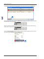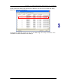
1
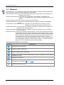
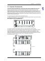
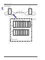
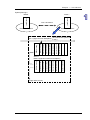
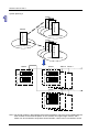
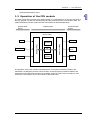
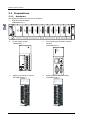
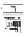
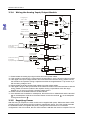
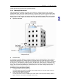
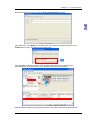
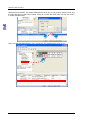
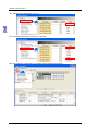
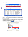
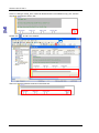
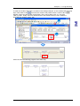
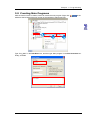
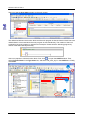
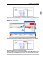
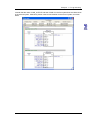
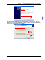
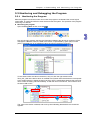
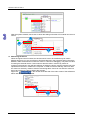
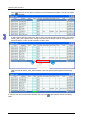
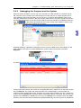
Chapter 1
Introduction
Table of Contents
1.1
1.2
1.3
Manuals.....................................................................................................1-2
System Frameworks..................................................................................1-3
Operation of the CPU module ...................................................................1-9
1-1
A H 5 00 Q uick Star t
1.1 Manuals
Delta Electronics, Inc. provides users with the manuals related to the AH500 series programmable
logic controllers according to different application requirements.
AH500 Hardware Manual: It introduces hardware specifications, addressing, wiring, maintenance,
troubleshooting, and etc.
AH500 Operation Manual: It introduces the configuration of the hardware, the setting of the
connection, the operation of the CPU module, the setting of the software,
and etc.
AH500 Programming Manual: It introduces devices and instructions.
AH500 Module Manual: It introduces module specifications, installation, setting, troubleshooting,
and etc.
AH500 Motion Control Module Manual: It introduces the specifications for the motion control
modules, the wiring, the instructions, and the functions.
ISPSoft User Manual: It introduces the use of ISPSoft, including the variables, the connection, the
programs, and the function blocks.
PMSoft User Manual: It introduces the use of PMSoft, including the editing mode, the connection,
and the encryption.
AH500 Quick Start: It helps users create and use the system in a short time. AH500 Quick Start not
only introduces the basic system frameworks, but also teaches users to write a
program step by step by means of simple examples, and download the program
which includes the variables and the function blocks to the CPU module. Users
can experience the convenience brought by the new functions. If an error
occurs when the system runs, please refer to section 3.3.2 for more information
about debugging the program. (Please refer to chapter 12 in AH500 Operation
Manual for more information about the troubleshooting.)
The graphic representations in the manual
Graph
Significance
Clicking the left mouse button
Clicking the right mouse button
Double-clicking the left mouse button
Pressing and holding the left mouse button, and then moving the mouse without
releasing the button.
Typing with a keyboard
Operating sequence (The graphic representation is used when the operating sequence
is mentioned. For example,
and
.)
Number used with a picture
1-2
Ch ap te r 1 In tro duc tio n
1.2 System Frameworks
The AH500 series programmable logic controller is a medium type of programmable logic control
system. The execution speed and the memory capacity are increased. Besides, the complete
program development function of function blocks is supported. In order to meet users’ more
advanced application requirements, the AH500 series programmable logic controllers provide more
flexible system extension frameworks. Under such system frameworks, users do not need to use
several CPU modules to control the system because of the fact that there are too many I/O points or
the equipment is too far away. The completeness of the system is retained, and users can be more
efficient in developing the projects.
The minimum framework requirement for the AH500 system:
To create the AH500 system, one main backplane, one power supply module, and one CPU module
are needed for the operation of the CPU module.
Main backplane (four-slot AHBP04M1-5A)
Power supply
module
CPU module
The common framework of the AH500 system (for original equipment manufacturers):
The AH500 system can meet most equipment development requirements in the application field of
original equipment manufacturers. Generally speaking, one eight-slot main backplane or one
twelve-slot main backplane is chosen. Some advanced equipment can be used with a six-slot
extension backplane or an eight-slot extension backplane under the original framework to increase
the number of I/O points and the number of axes, or decrease the wiring cost.
The framework: Rack 1~rack 8
.
.
.
.
.
.
7 backplanes
1-3
A H 5 00 Q uick Star t
The configuration is as follows.
Rack 1 (eight-slot main backplane)
Motion control module
Motion control module
Motion control module
Motion control module
Motion control module
Motion control module
Network module
CPU module
Power supply
Rack 2 (eight-slot extension backplane)
Serial communication
module
Temperature
measurement module
Analog input module
Digital output module
Digital input module
Digital input module
Power supply
Eight racks at most
Note: Owing to the consideration to the data transmission speed, the motion control modules and
the network modules (exclusive of the serial communication modules) have to be installed
with the CPU module on the same backplane. Otherwise, the system can not operate
properly.
The common framework of the AH500 system (for system integration):
The AH500 system can meet most system control requirements in the application field of the system
integration. Generally speaking, the system framework is related to the positions of the equipments.
A control panel is usually placed among the equipments which are concentrated to save the wiring
cost. However, there is usually more than one concentration point, and the distance between the
concentration points is over 100 meters. If it is necessary for users to place more than two control
panels, the RTU modules are required. The remote framework of the AH500 system not only fills the
remote requirement, but also is combined with the extension of the local I/O. Under most conditions,
a control panel instead of a backplane can be regarded as a remote I/O station. In addition, the
backplanes, the power supply modules, and other modules are compatible with one another. The
convenience of planning the system is increased, and the difficulty of choosing the products is also
decreased.
1-4
Ch ap te r 1 In tro duc tio n
System framework: Rack 1~rack 8+RTU modules
Remote I/O
...
.
.
.
.
.
.
.
7 backplanes .
.
.
.
.
7 backplanes
Note: Users are provided with the special cables to connect the extension backplanes. The length of
a special cable can be up to 100 meters. They are also provided with the fiber cables which
are used with the special adapters. The length of a fiber cable can be up to 2 kilometers.
1-5
A H 5 00 Q uick Star t
System planning 1
Concentration point
Concentration point
Serial communication
module
Master
Rack 2 (eight-slot main backplane)
Remote master
Digital input module
Analog output module
Power supply
Digital output module
Digital output module
Digital output module
Analog input module
Analog input module
Analog input module
Digital input module
Digital input module
Digital input module
Digital input module
Digital input module
Network module
CPU module
Power supply
Eight racks at most
Control panel
Over 100 meters
Control panel
1-6
Slave 1
Master
Slave 1
Master
Rack 1 (eight-slot main backplane)
Ch ap te r 1 In tro duc tio n
System planning 2
Slave 1
Master
Control panel
Control panel
Over 100 meters
Concentration point
Concentration point
Sixty-three racks at most
Slave 1
(The remote I/O system is
Rack 1 (eight-slot main backplane) in use.)
Digital output module
Digital output module
Digital output module
Digital input module
Digital input module
Digital input module
Remote slave
Power supply
Slave 1
Rack 2 (eight-slot extension backplane)
Serial communication
module
Analog output module
Analog output module
Analog output module
Analog input module
Analog input module
Analog input module
Power supply
Eight racks at most
1-7
A H 5 00 Q uick Star t
System planning 3
Control panel
Control panel
設備集中區
設備集中區
Concentration point
Slave 1
Slave 2
Slave 3
Control panel
Control panel
Control panel
Concentration point
Control panel
Master
Control Panel
Slave 1
Slave 2
Slave 3
設備集中區
設備集中區
Concentration point
Master
Slave 1
Slave 2 Slave 3
Slave 1
Slave 2 Slave 3
Note: The remote masters in DeviceNet are the network modules. They have to be installed with the
CPU modules on the same backplane. A CPU module can support eight masters, and a
master can be connected to sixty-three slaves. Besides, a slave can be connected to seven
1-8
Ch ap te r 1 In tro duc tio n
extension backplanes at most.
1.3 Operation of the CPU module
The CPU module is the nucleus of the AH500 system. It is responsible for not only the execution of
the logic program, but also the data exchange and the processing of the communication data. The
relation between the AH500 system and the external devices are illustrated below.
External input
device
External output
device
AH500 system
CPU module
Switch
I/O
refresh
Program
operation
Relay
Output module
Pressure
Input module
Temperature
System
operation
AC motor
drive
Electric
valve
The operation of the CPU module is illustrated above. The system procedures related to the
initialization, the diagnosis, and the communication, and the program procedures related to the
external interrupts and timed interrupts are simplified. Users can refer to other manuals for more
information. The operation of the CPU module is described below.
1-9
A H 5 00 Q uick Star t
The CPU module is supplied with power.
The system enables the initialization.
y The non-latched memory is initialized.
y The user program is checked.
y The parameters in the CPU module are
checked.
y The parameters in the module table are
checked.
y The module table in the CPU module is
compared with the actual I/O configuration.
y The I/O setting is downloaded to the I/O
module.
y If the memory card is installed, whether to
execute the system copy procedure or not is
checked.
Diagnosis processing:
y The memory card and other setting are
checked.
y The I/O bus is checked.
y The system parameter is checked.
The data sent to the I/O module is refreshed.
y The data sent to the digital I/O module is
refreshed.
y The data sent to the analog I/O module is
refreshed.
y The data sent to other modules are refreshed.
Program execution:
y The user program is executed.
y The interrupt task is executed.
The data sent from the I/O module is refreshed.
y The data sent from the digital I/O module is
refreshed.
y The data sent from the analog I/O module is
refreshed.
y The data sent from other modules are
refreshed.
Communication service:
y The communication through the CPU module
y The communication through other I/O modules
y The internal communication between the CPU
module and the I/O module
1-10
Chapter 2
Programming
Table of Contents
2.1
Preparations ..............................................................................................2-2
2.1.1
Hardware............................................................................................2-2
2.1.2
Software .............................................................................................2-3
2.1.3
Tools and Materials ............................................................................2-3
2.2
Installation .................................................................................................2-3
2.2.1
Installing Modules...............................................................................2-3
2.2.2
Installing Removable Terminal Blocks ................................................2-4
2.3
Wiring ........................................................................................................2-6
2.3.1
Wiring the Power Supply Module .......................................................2-7
2.3.2
Wiring the Digital Input Module...........................................................2-9
2.3.3
Wiring the Digital Output Module........................................................2-9
2.3.4
Wiring the Analog Input/Output Module............................................2-10
2.3.5
Supplying Power ..............................................................................2-10
2.4
Exemplification ........................................................................................2-11
2.5
Creating Projects .....................................................................................2-12
2.6
Hardware Configuration...........................................................................2-14
2.7
Creating Global Symbols.........................................................................2-19
2.8
Creating Function Blocks.........................................................................2-20
2.9
Creating Main Programs..........................................................................2-29
2-1
A H 5 00 Q uick Star t
2.1 Preparations
2.1.1
Hardware
The hardware needed in the example is as follows.
1.
Eight-slot main backplane
AHBP08M1-5A x 1
POWER
2.
CPU
I/O0
I/O1
I/O2
I/O3
3.
Power supply module
AHPS05-5A x 1
PS05
PO WER
I/O4
I/O5
I/O6
I/O7
CPU module (with the built-in network
function)
AHCPU530-EN x 1
C PU5 3 0-EN
RU N
ERR OR
BU S FAUL T
SYST EM
COM
VS
Ether net
VS
NC
FG
USB
LG
COM
N
INPUT
L
4.
Digital input module (16 inputs)
AH16AM10N-5A x 1
16AM10N
5.
Digital output module (16 outputs)
AH16AN01R-5A x 1
16AN01R
5
5
7
0
1
7
0
1
8
9 10 11 12 13 14 15
8
9 10 11 12 13 14 15
2
0
3
4
6
L
1
2
6
1
3
CO M0
5
6
8
L
11
12
13
6
7
CO M1
L
8
9
L
L
10
11
L
14
15
5
L
9
10
4
L
L
7
CO M2
12
L
L
13
14
L
S /S
S /S
2 4VD C 5 m A
4
2
L
4
3
0
L
L
3
2
L
15
CO M3
2 4VD C
/2 4 0VA C 2 A
2-2
Ch ap te r 2 Prog ramming
6.
Analog input/output module (6 channels)
AH06XA-5A x 1
06XA
RUN
E RRO R
V0
V0
R0
V1
V1
R1
AI
V2
V2
R2
V3
V3
R3
V0
I0
AO CO M
V1
I1
ZP
UP
FE
1 0V, 2 0m A
1 0V,0 /4 ~ 20 m A
2.1.2
Software
The software needed in the example is as follows.
z
ISPSoft version 2.0 or above
z
COMMGR version 1.0 or above
2.1.3
Tools and Materials
The tools and the materials need in the example are as follows.
z
A personal computer in which the software mentioned above is installed
z
A 100~240 V AC and 50/60 Hz power supply socket
z
A 24 V DC power supply
z
A cable
z
A screwdriver
z
An USB cable or a network cable (If users want to connect the Ethernet port or the COM port
(RS-232/RS-485) on the CPU module to the computer, they can refer to section 2.3.2 in
ISPSoft User Manual for more information. If users want to know more about installing the
USB driver, they can refer to appendix A in AH500 Operation Manual.)
z
If necessary, users can prepare the accessories such as a switch and a bulb (to simulate the
activity of the external equipment).
2.2 Installation
2.2.1
Installing Modules
Please install the modules on the main backplane, as illustrated below.
Connect the module to the connector on the backplane, make sure that the module is installed on
the backplane properly, and tighen the the screw.
2-3
A H 5 00 Q uick Star t
1.
2.
Insert the projection under the module into the hole in the backplane.
Push the module in the direction indicated by the arrow until it clicks.
3.
Tighten the screw on the module.
2.2.2
Installing Removable Terminal Blocks
Please install the removable terminal block on the module, as illustrated below.
z Installation
1. Level the terminal block at the printed circuit board, and press it into the module.
2-4
Ch ap te r 2 Prog ramming
2. Press the clip in the direction indicated by the arrow.
z Removal
1. Pull the clip in the direction indicated by the arrow.
2. Pull up the clip.
2-5
A H 5 00 Q uick Star t
3. The terminal block is removed.
2.3 Wiring
After the modules are installed, the wiring of the modules follows. In order for the following example
to proceed smoothly, the power supply module and the analog module have to be wired. Be sure to
cut off the power supply before wiring the modules. To lend convenience and reality to the
simulation, the signal lines can be connected to the switch and the bulb according to the personal
needs. The rough framework is as follows.
100~240 V AC
+
DC 24 V
power supply -
L
N
UP
ZP
CPU530-EN
PS05
POWER
16AM10N
RUN
ERROR
2
3
16AN01R
0
1
8
9 10 11 12 13 14 15
4
5
6
7
2
3
06XA
0
1
8
9 10 11 12 13 14 15
4
5
6
RUN
7
ERROR
BUS FAULT
SYSTEM
COM
0
L
1
L
3
Ethernet
6
8
NC
L
FG
L
INPUT
10
L
11
12
L
V3
VI3
9
I3
10
VO0
11
IO0
COM2
15
L
L
S/S
AO AG
12
L
S/S
VO1
13
IO1
14
ZP
15
UP
COM3
SG
24VDC
/240VAC 2A
24VDC 5mA
S/S
Switch
2-6
VI2
I2
8
L
14
V2
6
L
+
DC 24 V
power supply -
AI
5
7
L
N
L
I1
COM1
13
LG
V1
VI1
4
L
9
COM
3
L
7
USB
VI0
I0
COM0
5
VS
V0
1
2
L
4
VS
0
L
2
±10V,± 20mA
±10V,0/4~20mA
COM
Bulb
Signal
simulator
Ch ap te r 2 Prog ramming
The wiring of the modules is described in detail below. (Please refer to AH500 Hardware Manual for
more information.)
2.3.1
z
z
z
z
z
z
Wiring the Power Supply Module
The alternating-current input voltage is within the range between 100 V AC and 240 V AC.
Please connect the power supply to the terminals L and N. If the 110 V AC or the 220 V AC
power supply is connected to the input terminals VS+ and VS-, the PLC will be
damaged.
In order to ensure that the 24 V DC external power supply is provided stably, it can be
connected to VS+ and VS-. If the PLC detects that the voltage of the external power supply is
lower than the working voltage, users can write a protective program. (Please refer to section
6.6 in AH500 Operation Manual for more information.)
The length of the wire connecting with the ground is 1.6 millimeters.
If the power cut lasts for less than 10 milliseconds, the PLC keeps running without being
affected. If the power cut lasts for long, or if the voltage of the power supply decreases, the
PLC stops running, and there is no output. When the power supply returns to normal, the PLC
resumes. (Users have to notice that there are latched auxiliary relays and registers in the PLC
when they write the program.)
Please use the single-core cable or the twin-core cable. The diameter of the cable used should
be with the range between 12 AWG and 22 AWG. The torque applied to the terminal screw
should be within the range between 5 kg-cm (4.3 Ib-in) and 8 kg-cm (6.9 Ib-in). Please use the
copper conducting wire. The temperature of the copper conducting wire should be 60/75°C.
Safety wiring: The PLC controls many devices, and the activity of any device affects the
activity of other devices. If a device breaks down, the whole automatic control system goes out
of control, and the danger occurs. The protection circuit is as follows.
2-7
A H 5 00 Q uick Star t
④
⑤
⑥
⑦
Alternating-current power supply: 100~240 V AC, and 50/60 Hz
Circuit breaker
Emergency stop: The emergency stop button can be used to cut off the power when an
emergency occurs.
Power indicator
AC power load
Fuse (2A)
The ground impedance is less than 100 Ω.
○
8
Direct-current power supply: 24 V DC
①
②
③
2-8
Ch ap te r 2 Prog ramming
2.3.2
Wiring the Digital Input Module
The input signal is the direct-current power input. Sinking and sourcing are current driving
capabilities of a circuit. They are defined as follows.
z
Sinking
z
Sourcing
2.3.3
Wiring the Digital Output Module
The output unit can be the relay output, the transistor output, or the TRIAC output.
Relay output
Transistor output
TRIAC output
2-9
A H 5 00 Q uick Star t
2.3.4
Wiring the Analog Input/Output Module
AG
Voltage input
-10 V~+10 V
CH0
*3
V0+
I0+
1M
1M
VI0Shielded cable*1
CH0
250
*6
SG
AG
Current input
CH3
-20 mA~+20 mA
V3+
*2
1M
250
VI3Shielded cable*1
*6
SG
Voltage output
-10 V~+10 V
An AC motor drive,
a recorder,
a proportioning valve...
CH0
VO0
*5
CH0
IO0
Shielded cable*4
AG
*6
SG
Current output
AG
CH1
0 mA~20 mA
An AC motor drive,
a recorder,
a proportioning valve...
CH3
1M
VO1
CH1
IO1
AG
Shieleded cable*4
AG
*6
SG
*7
DC24V
SG
ZP
DC/DC
UP
converter
+15V
AG
-15V
*1. Please isolate the analog input signal cables from other power cables.
*2. If the module is connected to a current signal, the terminals V+ and I+ have to be short-circuited.
*3. If the ripple in the input voltage results in the noise interference with the wiring, please connect
the module to the capacitor having a capacitance within the range between 0.1 μF and 0.47 μF
with a working voltage of 25 V.
*4. Please isolate the analog output signal cables from other power cables.
*5. If the ripple is large for the input terminal of the load and results in the noise interference with the
wiring, please connect the module to the capacitor having a capacitance within the range
between 0.1 μF and 0.47 μF with a working voltage of 25 V.
*6. Please connect the shielded cables to the terminal SG.
*7. Once AH06XA-5A is installed on a backplane, the terminal SG on AH06XA-5A and the terminal
on the backplane will be short-circuited. Please connect the terminal
on the backplane
.
to the ground terminal
2.3.5
Supplying Power
After the wiring is complete, the CPU module can be supplied with power. Make sure that the CPU
module is set to STOP before the CPU module is supplied with power. The CPU module executes
the initialization after it is supplied with power. Owing to the fact that there is no hardware
configuration in the CPU module, the error LED indicator is ON after the check is complete. This is a
2-10
Ch ap te r 2 Prog ramming
normal phenomenon which can be ignored temporarily.
2.4 Exemplification
After the hardware is installed, the wiring of the modules is complete, and the CPU module is
supplied with power, users can write the program. In order for users to have a precise object and
direction, the manual provides users with an example before they write the program. The manual
teaches users how to create a new project and how to download the program to the CPU module
step by step. The following are the contents of the example and the illustration of the framework.
z
System framework
z
Control action
The example is the basic design of the water supply of the multi-storey building. The tap-water is
automatically supplied to the underground pool, and the water in the underground pool can be
transported to the water tower on the top of the building through the pump. The water is distributed
to every story in the building by means of gravity, and the action of the pump is controlled by the
level switch of the underground pool and that that of the water tower. In order to monitor the water
supply, the level meter is installed in the underground pool. The water storage capacity of the
underground pool is monitored at all times.
The devices connected to the modules:
1.
A single-point level switch (contact A)
The single-point level switch is installed in the underground pool, and the signal contact is
connected to the digital input module.
2.
A two-point level switch (contact A)
The two-point level switch is installed in the water tower on the top of the building, and the
signal contact is connected to the digital input module.
2 - 11
A H 5 00 Q uick Star t
3.
4.
A pump
The pump is installed near the underground pool. However, the device to which the PLC
actually connects is not the pump but the control panel. Generally speaking, three digital inputs
and one digital output are connected to the digital input/output module. (Remote control x 1 (DI)
& Run x 1 (DI) & Trip x 1 (DI) & Start x 1 (DO))
A level meter
The level meter is installed in the underground pool, and the signal contact is connected to the
analog input module. (0~10V correspond to 0~10M. 0 V represents that the water is 0.0 meters
deep, and 10 V represents that the water is 10.0 meters deep.)
The control condition of the pump:
1.
Start: If the water level inside the water tower is low and that inside the underground pool is not
low, the pump will refill the water tower.
2.
Stop: If the water level inside the water tower is high, or if the water level inside the
underground pool is low, the pump stops running.
2.5 Creating Projects
After users install the hardware and understand the control logic in the example, they can write the
program.
Step 1: Open ISPSoft (StartÆProgramsÆ Delta Industrial
AutomationÆPLCÆISPSoftx.xxÆISPSoftx.xx)
The start screen of the software:
Entering the main screen of the software:
Step 2: Click
to create a project. The example is related to the water supply, and therefore the
project name is SPW. The PLC type is AHCPU530-EN, and the file path is the default path.
Finally, click OK.
2-12
Ch ap te r 2 Prog ramming
Next, the environment of the project is displayed, and the project name SPW appears in the upper
left corner.
The operation interface of the software:
n Function area: The main functions of the software are in this area. Many functions which are
frequently used are placed on the toolbar, and other functions are placed on the menus.
o Project management area: The framework of the project is displayed in this area. Users can
understand the relation among the objects on the basis of the tree structure. The efficiency in
managing the project is also increased.
p Work area: The editing work is in this area.
q Output area: The information resulting from the execution of the function is displayed in this
r
area.
Status area: The project and the communication information are displayed in this area.
2-13
A H 5 00 Q uick Star t
2.6 Hardware Configuration
After the project is created, users can configure the hardware. Suppose the configuration is as
follows.
z Digital input module 16AM10N-5A/16AM30N-5A (16 inputs)ÆX0.0~X0.15
z Digital output module 16AN01R-5A/16AN01T-5A/16AN01P-5A/16AN01S-5A (16 outputs)
ÆY0.0 ~ Y0.15
z Four-channel analog input module AH06XA-5AÆD0~D7
z Two-channel analog output module AH06XA-5AÆD100~D103
z The water level inside the underground pool is low.ÆX0.0
z The water level inside the water tower is low.ÆX0.2
z The water level inside the water tower is high.ÆX0.3
z Remote control of the pumpÆX0.5
z The pump runs.ÆX0.6
z The pump trips.ÆX0.7
z The pump starts.ÆY0.0
z Water level inside the underground poolÆD0
With the information above, users can configure the hardware practically. Double-click
in the window at the left side of the main screen of the software to open the configuration window.
Users can configure the hardware according to the information above. After users type “SPW PLC
Control Station”, the project can be shared.
2-14
Ch ap te r 2 Prog ramming
Double-click the CPU module to open the PLC Parameter Setting window.
Type “SPW PLC” in the Name box, and then type “The example in AH500 Quick Start” in the
Comment box. Finally, click OK, and close the window.
User can begin to place the modules. First, find the first module which is needed, that is,
AH16AM10N-5A, in the product list. Then, drag the module to I/O 0 and drop it.
After the module is placed in the appropriate position, the system automatically distributes the
2-15
A H 5 00 Q uick Star t
addresses to the module. The default addresses are X0.0~X0.15. They exactly meet the need, and
therefore they do not need to be modified. If they do not meet the need, users can click the column
to modify the addresses.
Users can drag AH16AN01R-5A to I/O 1 and drop it. The addresses are Y0.0~Y0.15.
2-16
Ch ap te r 2 Prog ramming
Users can drag AH06XA-5A to I/O 2 and drop it. The input device range is D0~D7, and the output
device range is D100~D103. (The default output device range is D8~D11. Please remember to
modify it.)
In addition to specifying the input device range and the output device range, users also have to
specify the version of the firmware for the analog input/output module. Please select the version of
the firmware according to the version of the firmware in the module.
In order to complete the basic setting, users need to set the relation between the signals and the
conversion values for the analog module. Double-click the module to open the Parameter Setting
window.
2-17
A H 5 00 Q uick Star t
The voltages of the signals are 0 V~10 V.
The conversion values are 0.0 and 10.0. Click OK.
After the hardware configuration is complete, please save the file and exit.
2-18
Ch ap te r 2 Prog ramming
2.7 Creating Global Symbols
In order to make the program more readable and the connection with the SCADA system more
convenient, the I/O addresses are accompanied with the global symbols. Users can use the
symbols when they write the program. The global symbol table also supports import and export. As
to the system equipped with many inputs and outputs, users can use Microsoft Excel to make the
editing more convenient.
The global symbols created are as follows.
Global symbol table
Bit (for the I/O on the PLC)
Address
Identifier
Data type
X0.0
Tank_B1F_LSW
BOOL
X0.2
Tank_RF_LSW
BOOL
X0.3
Tank_RF_HSW
BOOL
X0.5
SPP01_Remote
BOOL
X0.6
SPP01_Run
BOOL
X0.7
SPP01_Trip
BOOL
Y0.0
SPP01_Start
BOOL
D0
Tank_B1F_LT
REAL
Bit (for the SCADA system)
M0
SPP01_Auto
BOOL
M1
SPP01_Man_SW
BOOL
With the information above, users can create the global symbols. Double-click
in the
window at the left side of the main screen of the software to open the Global Symbols window.
Double-click the blank to open the Add Symbol window. Type “X0.0” in the Address box. The
default values in the Type… box, the Initial box, and the Comment… box remain unchanged. Click
OK to complete the typing.
2-19
A H 5 00 Q uick Star t
Users can see a new piece of data.
Users can create the global symbols for the data in the table above in the same way. (For the analog
module, the data type is a real floating-point number. Therefore, the symbol occupies two data
registers, and the address in the Address box is the initial address.)
2.8 Creating Function Blocks
The procedure in this example is to create a function block first. Users also can create the main
program first. There is no absolute relation between the function block and the main program. They
are actually executed alternately. However, users are recommended to create a function first when
the function is used repeatedly.
The control relation among the underground pool, the water tower, and the pump can be
represented by a function block. There are usually two water systems in a multi-storey building. If
users create the function blocks, they only need to change the variables of the input pins and those
of the output pins to complete the second water system.
Users can create a function block which contains the relation among the underground pool, the
in the window at the left side of the main
water tower, and the pump. Right-click
screen of the software to add a new POU.
2-20
Ch ap te r 2 Prog ramming
Type “FB_SPP_Sys” in the POU Name box, and then type “Supply Water Pump Control Function” in
the POU Comment box. Finally, click OK.
Users can see the FB_SPP_Sys window on the main screen.
Users need to create the local symbols. In order to make the use of the function block more
convenient, the system automatically distributes the addresses to the module, and users are not
allowed to type the addresses by themselves. Users surely can use the addresses and the global
symbols in the internal program. However, the use of the addresses or the uses of the global
symbols will decrease the convenience of using the function block. (If a local symbol is the same as
a global symbol, the local symbol used in the function block has high priority.)
The local symbols created are as follows.
Declaration type
Identifier
Data type
VAR_INPUT
Tank_B_LSW
BOOL
VAR_INPUT
Tank_R_LSW
BOOL
VAR_INPUT
Tank_R_HSW
BOOL
VAR_INPUT
Pump_Remote
BOOL
VAR_INPUT
Pump_Run
BOOL
VAR_INPUT
Pump_Trip
BOOL
VAR_IN_OUT
Pump_Auto
BOOL
VAR_IN_OUT
Pump_Man_SW
BOOL
VAR_OUTPUT
Pump_Start
BOOL
VAR
Pump_Out
BOOL
2-21
A H 5 00 Q uick Star t
VAR_INPUT
When the program is executed, the value of the external variable is brought into the internal variable.
If the value of the corresponding internal variable is altered, it is not transmitted to the external
variable. VAR_INPUT is often used if the value of the external variable should not be modified. Most
of inputs in this example are digital inputs, and these inputs should not be modified. The modification
of the values of these variables affects the execution of the program or the use of the function block.
In order to prevent the values of these variables from being modified in the program, the declaration
type should be VAR_INPUT.
VAR_IN_OUT
When the program is executed, the value of the external variable is brought into the internal variable.
After the program comes to an end, the value is transmitted to the external variable. VAR_IN_OUT
is often used if the value of the variable should be modified. Generally speaking, Pump_Auto and
Pump_Man_SW in this example are used in the SCADA system to set the control mode of the pump.
It seems that VAR_INPUT meets the need. However, users need to switch the control mode of the
pump from the automatic mode to the manual mode to stop the command from being outputted
when the pump trips. Therefore, the declaration type for these two variables should be
VAR_IN_OUT.
VAR_OUTPUT
When the program is executed, the value of the external variable is not brought into the internal
variable, but the value memorized before is used instead. After the program comes to an end, the
value is transmitted to the external variable. Generally speaking, the variable appears at the output
of the instruction.
VAR
When the program is executed, VAR is regarded as an internal variable, and the value memorized
before is used. Generally speaking, the variable is used as a register when it is used in the program.
If the same variable (function block type) is assigned to the function blocks which are called many
times in the program, the initial value of VAR_OUTPUT and that of VAR are not necessarily the
same as those used last time.
Users can create the local symbols as follows.
2-22
Ch ap te r 2 Prog ramming
Users can begin to write the program in the function block. In order to improve the convenience of
scanning the program, users are recommended to write the comments. If users want to write the
.
network comments, they have to click
Type the following description as the comment on network 1. If users want to start a new line of text
at a specific point, they can press Alt+Enter on the keyboard.
Users can begin to edit the program code. The programming language used here is the ladder
diagram. Please click
, and then move the mouse to the red frame. If the cursor becomes
users can click the left mouse button.
,
2-23
A H 5 00 Q uick Star t
Click ???, and type “Pump_Remote”. When “Pump_Remote” is typed, the drop-down list appears.
Users can select the item directly, or type the words by themselves. After “Pump_Remote” is typed,
press the enter key.
(If the address appears, users can click
to switch the mode. In either mode, users can use the
words or the addresses when they write the program.)
Users can write the following program in the same way.
2-24
Ch ap te r 2 Prog ramming
To meet the condition that there is water in the underground pool and no water in the water tower,
the state of Tank_R_LSW should be OFF. Users can double-click the contact marked
“Tank_R_LSW”, and the drop-down list appears. Select “Normally Closed”.
Please click
, and then move the mouse to the red frame.
2-25
A H 5 00 Q uick Star t
Click ???, and type “Pump_Out”. Users can double-click the coil marked “Pump_Out”, and the
drop-down list appears. Select “Set”.
Please click
, to add a new network.
Users can write the following program in the same way.
2-26
Ch ap te r 2 Prog ramming
To meet the condition that there is no water in the underground pool, or the condition that the pump
, and move the mouse to the position under a contact. When
trips, users need to click
appears, users can click the left mouse button. Then, users need to click ???, and type
“Tank_B_LSW”. Finally, users can double-click the coil marked “Tank_B_LSW”. When the
drop-down list appears, select “Set”.
Users can write the following program in the same way.
2-27
A H 5 00 Q uick Star t
So far the automatic program control is complete. Please write the following program in the same
way.
Finally, users need to save the file, and the function block is created.
2-28
Ch ap te r 2 Prog ramming
2.9 Creating Main Programs
After the function block is created, users can create the main program. Right-click
window at the left side of the main screen of the software to add a new POU.
in the
Type “Prog_Main” in the POU Name box, and then type “Main program” in the POU Comment box.
Finally, click OK.
2-29
A H 5 00 Q uick Star t
Users can see the Prog_Main window on the main screen.
The difference between the function block and the main program is that the function block has to be
called before it is executed while the main program is executed directly. The creation of the local
symbols for the main program is omitted in this example. Please write the following program by
means of the skills learned previously.
Users can prepare to call the function block. First, click
to open the API/FB window. Then,
select Function Block in the Type Class box, and select “FB_SPP_Sys” in the API/FB box. Finally,
click Insert.
2-30
Ch ap te r 2 Prog ramming
After the function block interface appears, type the identifiers as shown below.
Users need to create a data block for the function block. The data block can be created as a global
symbol or a local symbol, but it is created as a local symbol in the main program here. Notice that
users need to select Function Block in the Type Class box, and select “FB_SPP_Sys” in the Type
box. Please type “SPP01_DB” in the Identifier box, and type “SPP01 Data Block” in the
Comment… box, as show below.
After the local symbol is created, the identifier can be given to the function block. (The data type
should be the same with the name of the function block.)
After the file is saved, the writing of the program is complete.
Users can click
to check the syntax of the current program, and click
to compile the project.
The compiling of the project is different from the checking of the syntax in that the former involves
2-31
A H 5 00 Q uick Star t
not only the function of checking the syntax, but also the function of compiling all programs and the
contents of the function block.
Note: In order to help users understand the control program, the example provided here is simple.
The actual control program is much more complex because the functions related to judging
the start failure and the conversion from the local control to the remote control have to be
taken into account. Users need to use the applied instructions in the window at the left side of
the main screen to write a program for these functions. (Please refer to ISPSoft User Manual
for more information.)
If users need to create the second system, they only need to call “FB_SPP_Sys” again, and type the
identifier. Please notice that the same data block can not be used in the two systems unless user
2-32
Ch ap te r 2 Prog ramming
consider that the value of VAR_OUTPUT and that of VAR of in the first system does not affect those
in the second system. Otherwise, please create a new identifier for the second system, as shown
below.
2-33
A H 5 00 Q uick Star t
MEMO
2-34
Chapter 3
Downloading and
Monitoring the Program
Table of Contents
3.1
Setting COMMGR .....................................................................................3-5
3.1.1
Enabling COMMGR............................................................................3-5
3.1.2
Opening the COMMGR Window ........................................................3-5
3.1.3
Setting the Communication ................................................................3-5
3.2
Downloading the Program .........................................................................3-6
3.2.1
Setting the Communication ................................................................3-6
3.2.2
Downloading the Hardware Configuration..........................................3-7
3.2.3
Downloading the Program..................................................................3-8
3.3
Monitoring and Debugging the Program....................................................3-9
3.3.1
Monitoring the Program......................................................................3-9
3.3.2
Debugging the Program and the System .........................................3-13
3-1
A H 5 00 Q uick Star t
After the writing of the program is complete, users can prepare to download the program. In order to
increase the functions and the convenience, the latest software package is divided into COMMGR
and ISPSoft. In addition to preparing the hardware, supplying power to the CPU module, and
installing the USB driver, users need to set the communication software to communicate with the
CPU module.
If the computer is not connected to the USB port on the CPU module, please connect the CPU
module to the computer with an USB cable. The following window will appear.
Please complete the setting according to the steps below.
3-2
Ch ap te r 3 Down lo ading a nd Mo nitor ing th e Pr ogr am
The path C:\Program Files\Delta Industrial Automation\ISPSoftx.xx\drivers\Delta_PLC_USB_Driver
shown in the picture below is the folder where the software is installed. If the path is modified, please
select the folder where the software will be installed.
3-3
A H 5 00 Q uick Star t
After the software is installed, users can see the USB driver in the Device Manager window.
(The COM number of the USB may vary from computer to computer.)
3-4
Ch ap te r 3 Down lo ading a nd Mo nitor ing th e Pr ogr am
3.1 Setting COMMGR
3.1.1
Enabling COMMGR
After the software is installed, the shortcut for COMMGR automatically appears in the notification
area in the operating system. Whenever the computer is turned on, users can see
located at
the far right of the taskbar. If users do not see the icon, they can enable the software manually. The
shortcut to enabling the software is StartÆProgramsÆ Delta Industrial
AutomationÆCommunicationÆCOMMGRÆCOMMGR.
3.1.2
Opening the COMMGR Window
After COMMGR is enabled, users can double-click
3.1.3
to open the setting interface below.
Setting the Communication
After the interface is opened, users can begin to set the communication. Owing to the fact that the
computer is connected to the CPU module with an USB cable, an USB driver is created. First, click
Add. Then, complete the following setting.
After the setting is complete, the driver appears in the COMMGR window. Please click Start to start
the driver.
3-5
A H 5 00 Q uick Star t
3.2 Downloading the Program
After the editing above is complete, users need to download the parameters and the program to the
CPU module. In this example, the data which is downloaded to the PLC is the hardware
configuration, the CPU parameters, and the program.
3.2.1
Setting the Communication
After the setting of COMMGR is complete, users can set the communication in ISPSoft. First, find
Communication Settings… on the Tools menu.
After the Communication Setting window appears, please select USB_Drive in the Driver box, and
click OK.
Users can see the information about the communication setting in the lower right corner of the
screen.
3-6
Ch ap te r 3 Down lo ading a nd Mo nitor ing th e Pr ogr am
3.2.2
Downloading the Hardware Configuration
The hardware configuration is downloaded first. Open the SPW-HWCONFIG window as shown
below.
After users click
, the Transfer Items window will appear. After the users click OK, the
hardware configuration and the CPU parameters will be downloaded to the CPU module.
3-7
A H 5 00 Q uick Star t
If the CPU module which is actually connected is different from the setting in ISPsoft, the HWCNFIG
window will appear. Users have to make sure that the CPU module which is actually connected is
the CPU module to which the hardware configuration and the CPU parameters will be downloaded.
After users click Yes, the hardware configuration and the CPU parameters will be downloaded to the
CPU module. After the hardware configuration and the CPU parameters are downloaded to the CPU
module, the error LED indicator on the CPU module will not be ON.
After the downloading of the parameters is complete, please close the SPW-HWCONFIG window.
(If users use a network module or a motion control module, they have to open the corresponding
software to download the related parameters.)
3.2.3
Downloading the Program
After the hardware configuration is downloaded, users can begin to download the program. The
project has been compiled previously. If the program is modified, users can click
to check the
syntax. After the compiling of the program is successful, users can click
to download the
program.
There are several transfer options in the Transfer Setup window. The object code is the necessary
condition for the operation of the CPU module, and therefore the Object Code checkbox is selected.
In order to maintain the program, the Program checkbox and the Comments checkbox are
selected in this example. The current project will be backed up in the CPU module, and the program
will not be lost. Besides, if users want to modify the program on the spot, and forget to bring the
original program, they can upload the original program from the CPU module to the computer to
modify the program.
After users click OK, the downloading of the program is complete.
Finally, check the I/O LED indicator on the module and the status of the equipment. After users
make sure that the whole system can be tested, they have to switch the CPU module on so that the
CPU module starts to run.
3-8
Ch ap te r 3 Down lo ading a nd Mo nitor ing th e Pr ogr am
3.3 Monitoring and Debugging the Program
3.3.1
Monitoring the Program
When the program is executed, users can monitor the program to understand the current logical
control state, or modify the values in some devices to test the system. The operation of the program
monitoring is as follows.
z Monitoring the program
Open the Prog_Main window, and click
.
Not only the logic program, but also the information related to the devices is monitored. (If the
data type is a Boolean value, the state of the device is represented by green (ON) or white
(OFF). If the data type is not a Boolean value, the value in the device is shown.)
If users want to alter the value in the device, they can click the right mouse button.
Tank_B1F_LSW is the device which is modified here. Please notice that the device corresponds
to an actual I/O device. Setting the device to ON or OFF is meaningless because the actual I/O
value covers the setting value immediately. To alter the value in the device, users need to force
the device ON or OFF.
The value in the device is altered, and a lock symbol indicating that the device is forced ON
appears.
3-9
A H 5 00 Q uick Star t
After the system is tested, users have to cancel the setting so that the CPU module can return to
normal.
z
Monitoring the device
When the logical control is tested, the devices which have to be modified may be used in
different programs. It is not convenient to find these devices in the programs and monitor them.
Besides, users sometimes do not alter the value in a device for debugging. They alter the value
for testing the external device. If users want to alter the value in a device by means of
monitoring the program, they will have difficulty in finding the device, and the program has to be
uploaded from the CPU module to the computer. In order to solve the difficulty, users can alter
the value in a device by means of a device monitoring table. User even can alter the value in a
device and monitor the device without the program.
in the window at the left side of the main screen of the software to
Right-click
add a new device monitoring table.
3-10
Ch ap te r 3 Down lo ading a nd Mo nitor ing th e Pr ogr am
Type “SPP01_Table” in the Monitor Table Name box, and click OK.
Users can right-click a blank area in the Monitor Table window, and then click Select Symbols.
They can also double-click a blank area in the Monitor Table window to open the Device
Monitor Input window.
Click Select All, and then click Apply.
Click Cancel, and then save the file. The device monitoring table is as follows.
3 - 11
A H 5 00 Q uick Star t
Click
. Owing to the fact that only devices are monitored and modified, users do not need a
copy of the program.
If users want to alter the value in the device, they can click the right mouse button. The state of
SPP01_Man_SW is altered here. Owing to the fact that the device does not correspond to an
actual I/O device, users can set the device to ON or OFF.
After the state of SPP01_Man_SW is altered, users can get the following device monitoring
table.
If users do not want to monitor the devices, they can click
table.
3-12
and close the device monitoring
Ch ap te r 3 Down lo ading a nd Mo nitor ing th e Pr ogr am
3.3.2
Debugging the Program and the System
When the system operates, an error may occur, and the error LED indicator on a module may be
ON. If an error occurs, and the error LED indicator is not ON, the error is a logic program error. If
users follow the steps in the example, no error will occur. In order to demonstrate a system error,
users are asked to turn off the 24 V DC power supply. After the 24 V DC power supply is turned off,
the bus fault LED indicator on the CPU module and the error LED indicator on AH06XA-5A are ON.
Click
in the window at the left side of the main screen of the software, and then click
. The actual statuses of the modules are as follows.
Generally speaking, a hardware configuration error occurs if the BUS FAULT LED indicator on the
CPU module is ON. Users can select AH06XA-5A, click the right mouse button, and select
Diagnosis.
The information about the error is shown in the following picture.
As the picture above shows, the module is not supplied with power. Please turn on the power supply,
and click Refresh. The system will check the status of the module again. In this example, the
module has been supplied with power. Therefore, the system does not detect any error, and there is
no error log in the Current box, as shown below. If the system detects a new error, the new error log
appears in the Current box. Besides, the error log in the History box is cleared if users click Clear.
However, due to the fact that the modules are designed differently, the error logs are not maintained
3-13
A H 5 00 Q uick Star t
in all modules. In other words, for some modules, there may be no error log in the History box.
Since no error occurs, users can close the Module Error Log window. Besides, users can find that
the whole system returns to normal.
Users can set the CPU module to STOP, and then set it to RUN. When the CPU module runs, the
system and the screen of the software return to normal.
Close the SPW-HWCONFIG window, and return to the main screen of ISPSoft. Users can see the
error log by selecting PLC Error Log on the PLC menu.
3-14
Ch ap te r 3 Down lo ading a nd Mo nitor ing th e Pr ogr am
As the picture below shows, the power supply is abnormal, and an error occurs when the analog
data is converted into the digital data.
If users want to delete the old error log, they can click Clear Log. After closing the software, users
complete the operation illustrated in this example.
3-15
A H 5 00 Q uick Star t
MEMO
3-16