1
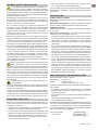
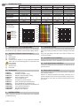
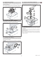
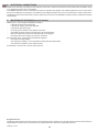
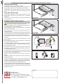
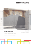
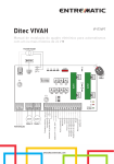
CUBIC6 IP1812 - rev. 2008-08-25 I GB F D E P DITEC S.p.A. Via Mons. Banfi, 3 - 21042 Caronno Pertusella (VA) - ITALY Tel. +39 02 963911 - Fax +39 02 9650314 www.ditec.it - [email protected] Manuale di installazione e manutenzione per automazioni per cancelli a battente. Installation and maintenance manual for automations for swing gates. Manuel d’installation et d’entretien pour portes à battant. Montage und Wartungshandbuch für automatisierte Drehtore. Manual para la instalaciòn y la manutenciòn para automatización para cancelas batientes. Manual de instalação e manutenção para portões de balanço. 2 3 5 4x0.5 mm² 7 7 TX - 4x0.5 mm² RX - 4x0.5 mm² 6 * * 6 1 4 7 7 TX - 4x0.5 mm² 3x1.5 mm² 2x1.5 mm² RX - 4x0.5 mm² (*) 3x0,75 mm² + 1x1,5 mm² [CUBIC6] 2x1,5 mm² [CUBIC6H] Fig. 1 CUBIC6 CUBIC6H Fig. 2 CUBIC6L CUBIC6LG max 110° CUBIC6 - IP1812 2 Fig. 3 CUBIC6TC max 180° Fig. 4 CUBIC6TI CUBIC6TIG max 180° 3 Fig. 5 CUBIC6 - IP1812 GENERAL SAFETY PRECAUTIONS - affix the CE mark on the motorised door pursuant to para. 1.7.3 of Schedule I of the Machine Directive. For more details, refer to the “Guidelines for producing technical documentation” available on Internet at the following address: www.ditec.it This installation manual is intended for professionally competent personnel only. Installation, electrical connections and adjustments must be performed in accordance with Good Working Methods and in compliance with applicable regulations. Before installing the product, carefully read the instructions. Bad installation could be hazardous. The packaging materials (plastic, polystyrene, etc.) should not be discarded in the environment or left within reach of children, as these are a potential source of hazard. Before installing the product, make sure it is in perfect condition. Do not install the product in an explosive environment and atmosphere: gas or inflammable fumes are a serious hazard risk. Before installing the motors, make all structural changes relating t o safety clearances and protection or segregation of all areas where there is risk of being crushed, cut or dragged, and danger areas in general. Make sure the existing structure is up to standard in terms of strength and stability. The motor manufacturer is not responsible for failure to use Good Working Methods in building the frames to be motorised or for any deformation occurring during use. The safety devices (photocells, safety edges, emergency stops, etc.) must be installed taking into account: applicable laws and directives, Good Working Methods, installation premises, system operating logic and the forces developed by the motorised door or gate. The safety devices must protect any areas where the risk exists of being crushed, cut or gragged, or where there are any other risks generated by the motorised door or gate. Apply hazard area notices required by applicable regulations. Each installation must clearly show the identification details of the motorised door or gate. Before making power connections, make sure the plate details correspond to those of the power mains.Fit an omnipolar disconnection switch with a contact opening gap of at least 3 mm. Make sure an adequate residual current circuit breaker and overcurrent cutout are fitted upstream of the electrical system. When necessary, connect the motorised door or gate to a reliable earth system made in accordance with applicable safety regulations. During installation, maintenance and repair, interrupt the power supply before opening the lid to access the electrical parts. To handle electronic parts, wear earthed antistatic conductive bracelets. The motor manufacturer declines all responsibility in the event of component parts being fitted that are not compatible with the safe an correct operation. For repairs or replacements of products only original spare parts must be used. The installer shall provide all information relating to automatic, manual and emergency operation of the motorised door or gate, and provide the user with operating instructions. APPLICATIONS CUBIC6-CUBIC6J-CUBIC6V Service life: 3 (minimum 10÷5 years of working life with 30÷60 cycles a day) Applications: FREQUENT (For vehicle or pedestrian accesses to town houses or small condominiums with frequent use). CUBIC6H-CUBIC6VH Service life: 4 (minimum 10÷5 years of working life with 100÷200 cycles a day). Applications: INTENSIVE (For all special applications with ongoing use such as toll gates and so on). - Performance characteristics are to be understood as referring to the recommended weight (approx. 2/3 of maximum permissible weight). A reduction in performance is to be expected when the access is made to operate at the maximum permissible weight. - Service class, running times, and the number of consecutive cycles are to be taken as merely indicative having been statistically determined under average operating conditions, and are therefore not necessarily applicable to specific conditions of use. During given time spans product performance characteristics will be such as not to require any special maintenance. - The actual performance characteristics of each automatic access may be affected by independent variables such as friction, balancing and environmental factors, all of which may substantially alter the performance characteristics of the automatic access or curtail its working life or parts thereof (including the automatic devices themselves). When setting up, specific local conditions must be duly borne in mind and the installation adapted accordingly for ensuring maximum durability and trouble-free operation. DECLARATION BY THE MANUFACTURER (Directive 98/37/EC, Annex II, sub B) Manufacturer: DITEC S.p.A. Address: via Mons. Banfi, 3 21042 Caronno P.lla (VA) - ITALY Herewith declares that the electromechanical automatic system series CUBIC: - is intended to be incorpored into machinery or to be assembled with other machinery to constitute machinery convered by Directive 98/37/EC; - is in conformity with the provisions of the following other EEC directives: Electromagnetic Compatibility Directive 89/336/EEC; Low Voltage Directive 73/23/EEC; and furthermore declares that it is not allowed to put the machinery into service until the machinery into which it is to be incorporated or of which it is to be a component has been found and declared to be in conformity with the provisions of Directive 98/37/EC and with national implementing legislation. MACHINERY DIRECTIVE Pursuant to Machine Directive (98/37/EC) the installer who motorises a door or gate has the same obligations as a machine manufacturer and shall: - prepare technical documentation containing the documents indicated on Schedule V of the Machine Directive; (The technical documentation shall be kept and placed at the disposal of competent national authorities for at least ten years starting on the date of manufacture of the motorised door); - draw up the EC declaration of conformity according to Schedule II-A of the Machine Directive; Caronno Pertusella, 03-12-2004 9 Fermo Bressanini (President) CUBIC6 - IP1812 GB GB 1. TECHNICAL DATA CUBIC6 230 V~ / 50 Hz 1,5 A 340 Nm 10 µF 18 s / 90° 3 - FREQUENT S2 = 15min S3 = 25% -20° C / +55° C IP67 E2 Power supply Absorption Torque Condenser Opening time Service class Intermittence Temperature Degree of protection Control panel Applications m = leaf width kg = leaf weight CUBIC6L* CUBIC6LG** CUBIC6TI* CUBIC6TIG** CUBIC6TC CUBIC6J 120 V~ / 60 Hz 4A 340 Nm 40 µF 18 s / 90° 3 - FREQUENT S2 = 15min S3 = 25% -20° C / +55° C IP67 E2J 600 kg 600 kg 600 kg 500 kg 500 kg 500 kg 400 kg 400 kg 400 kg 300 kg 300 kg 300 kg 200 kg 200 kg 200 kg 100 kg 100 kg 100 kg 2 3 4 5 m 1 2 3 4 5 m [CUBIC6CG**] REFERENCE TO ILLUSTRATIONS 1 2 3 4 5 m 3.1 Preliminary checks Check that the structure is sufficiently sturdy and that the hinge pivots are properly lubricated. Provide an opening and closing stop. Note: if the gate wing is more than 2.5 m wide, an electric lock should be installed. The given operating and performance features can only be guaranteed with the use of DITEC accessories and safety devices. 2.1 Standard installation references (fig. 1) [1] Radio [2]Flashing light [3]Key selector [4] Connect power supply to an type-approved omnipole switch with a contact opening gap of no less that 3 mm (not supplied) [5] Control panel [6] Geared motor [7] Photocells 3.2 Foundation case installation Install the foundation case as indicated in the relevant manual. 3.3 Lever mechanisms installation Choose and install the lever mechanisms as indicated in the relevant manual. 3.4 Wing release installation 2.2 Accessories Choose and install the door release mechanisms as indicated in the relevant manual. Attention: to install the releases more easily, we advise you to position the gate at the centre of the foundation casing and remove the lid, in such a way as to have enough space for fixing the screws. Foundation casing Oversize foundation casing Stainless steel foundation casing Gears foundation casing Lever mechanism kit Oversize lever mechanism kit Chain-operated lever mechanism kit Gear-operated lever mechanism kit Oversize gear-operated lever mechanism kit Lever-operated release kit Key-operated release kit Magnetic limit switch kit 3. INSTALLATION Unless otherwise specified, all measurements are expressed in millimetres (mm). CUBIC6 - IP1812 CUBIC6HV 24 V= 12 A 220 Nm 6÷13 s / 90° 4 - INTENSIVE S2 = 30min S3 = 50% -20° C / +55° C IP67 VIVAH 700 kg 1 CUBIC6C CUBIC6CG CUBIC6CY CUBIC6CTI CUBIC6L CUBIC6LG CUBIC6TC CUBIC6TI CUBIC6TIG CUBIC6SBL CUBIC6SBD CUBIC6FM CUBIC6V 230 V~ / 50 Hz 1,5 A 220 Nm 10 µF 9 s / 90° 3 - FREQUENT S2 = 15min S3 = 25% -20° C / +55° C IP67 E2 800 kg [CUBIC6C-CUBIC6CTI*] 2. CUBIC6H 24 V= 12 A 340 Nm 12÷25 s / 90° 4 - INTENSIVE S2 = 30min S3 = 50% -20° C / +55° C IP67 VIVAH 10 3.5 Geared motor installation 3.8 Installation with CUBIC6TI-CUBIC6TIG After installing the foundation casing, the respective lever and release mechanisms go before the installation of the gear motor as shown in the figure. Note: carefully clean the bottom of the foundation casing from dirt or cement to guarantee an even laying of the gearmotor. Fix the plate [A], then insert, fix and lubricate the gears [B], [C] and [D]. Position the sphere [E] as shown in the figure. D C B A E 3.6 Installation with CUBIC6L-CUBIC6LG Insert lever [A] on the gearmotor and position the mechanical stop [B] and [C] and adjust it, as shown in the figure. 3.9 CUBIC6FM installation A It is possible to limit the travel of the wing by means of magnetic limit switches. Choose and install the magnetic limit switches as indicated in the relative manual. Make the electrical connections as shown in the control panel. Attention: the magnetic limit switches cannot interrupt the power supply to the motor. B C 3.7 Installation with CUBIC6TC Insert pinion [A] and join the two pinions by means of the chain [B], as shown in the figure. Lubricate the chain and the lever mechanism as indicated in the figure. A B 11 CUBIC6 - IP1812 GB GB 4. ELECTRICAL CONNECTIONS Attention: the electrical connections for the extension of the motor cables must be made on the outside of the foundation casing in an appropriate junction box (not supplied). The CUBIC6 gearmotor can be connected to the E2 and LOGICM control panels. The CUBIC6J gearmotor can be connected to the E2J and LOGICMJ control panels. The CUBIC6H and CUBIC6VH gearmotors can be connected to the VIVAH control panel. The electrical connections and the start-up of the gearmotors are shown in the installation manuals of the E2, LOGICM and VIVAH control panels. 5. MAINTENANCE PROGRAM (every 6 months) Without 230 V~ power supply and batteries if present: - Lubricate the levers of the gearmotor. - Lubricate the rotation pivot of the gate leaf. - Lubricate the gate leaf hinges. - Check the good conditions of the electric connection. - Check that the fixing screws of the gearmotor are firmly tightened. - Clean the inside of the cases and check that drain is not clogged. - Check the value of the capacity of the motor condenser. Reconnect the 230 V~ power supply and batteries if present: - Check the power adjustment. - Check the good operation of all command and safety functions (photocells). - Check the good operation of the release system. Attention: For spare parts, see the spares price list. All right reserved All data and specifications have been drawn up and checked with the greatest care. The manufacturer cannot however take any responsibility for eventual errors, ommisions or incomplete data due to technical or illustrative purposes. CUBIC6 - IP1812 12 OPERATING INSTRUCTIONS FOR SWING GATES AUTOMATION CUBIC6 RELEASE INSTRUCTIONS In the event of failure or if there is no voltage: CUBIC6SBL: insert the lock release lever and rotate by 180° (fig.1). Release any electric lock. Manually open the gate. CUBIC6SBD: insert the lock release key in the lock and rotate by 180° (fig.2). Release any electric lock. Manually open the gate. BLOCKING INSTRUCTIONS CUBIC6SBL-CUBIC6SBD: rotate the lock release lever or key by 180°. Move the door wing manually until it is completely reattached. Attention: carry out the door wing blocking and release with the motor switched off. CUBIC6SBL Fig. 1 CUBIC6SBD Fig. 2 TEAR OFF AND DELIVER TO USER GENERAL SAFETY PRECAUTIONS The following precautions are an integral and essential part of the product and must be supplied to the user. Read them carefully as they contain important indications for the safe installation, use and maintenace. These instruction must be kept and forwarded to all possible future user of the system. This product must be used only for that which it has been expressely designed. Any other use is to be considered improper and therefore dangerous. The manufacturer cannot be held responsible for possible damage caused by improper, erroneous or unresonable use. Avoid operating in the proximity of the hinges or moving mechanical parts. Do not enter the field of action of the motorised door or gate while in motion. Do not obstruct the motion of the motorised door or gate as this may cause a situation of danger. Do not lean against or hang on to the barrier when it is moving. Do not allow children to play or stay within the field of action of the motorised door or gate. Keep remote control or any other control devices out of the reach of children, in order to avoid possible involuntary activation of the motorised door or gate. In case of breack down or malfunctioning of the product, disconnect from mains, do not attempt to repair or intervene directly and contact only qualified personnel. Failure to comply with the above may create a situation of danger. All cleaning, maintenance or repair work must be carried out by qualified personnel. In order to guarantee that the system works efficiently and correctly it is indispensable to comply with the manufacturer’s indications thus having the periodic maintenance of the motorised door or gate carried out by qualified personnel. In particular regular checks are recommended in order to verify that the safety devices are operating correctly. All installation, maintenance and repair work must be documented and made available to the user. ON OFF Installer: DITEC S.p.A. Via Mons. Banfi, 3 21042 Caronno Pertusella (VA) - ITALY Tel. +39 02 963911 - Fax +39 02 9650314 www.ditec.it - [email protected]