1
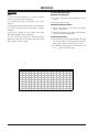
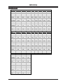
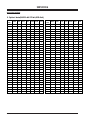
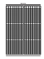
SERVICE MANUAL Model Series: L15V26 Product Type: Chassis: Manual Series: Manual Part #: Model Line: Product Year: LCD TV ML-012A CM154 923-03489 E 2002 CONTENTS Safety .......................................................... 2 General Info ................................................. 5 Servicing ................................................... 15 Parts ......................................................... 22 Diagrams .................................................... 27 Schematics ................................................. 33 Published June 2002 by Technical Publications Zenith Electronics Corporation 201 James Record Road Huntsville, Alabama 35824-1513 Printed in U.S.A. Copyright 2002 by Zenith Electronics Corporation PRODUCT SAFETY 1. Immediately before handling any semiconductor component or semiconductor-equipped assembly, drain off any electrostatic charge on the body by touching a known earth ground. Alternatively, obtain and wear a commercially available discharging wrist strap device, which should be removed for potential shock reasons prior to applying power to the unit under test. PRODUCT SAFETY IMPORTANT SAFETY NOTICE This manual was prepared for use only by properly trained audiovisual service technicians. When servicing this product, under no circumstances should the original design be modified or altered without permission from Zenith Electronics Corporation. All components should be replaced only with types identical to those in the original circuit and their physical location, wiring, and lead dress must conform to original layout upon completion of repairs. If any fuse (or Fusible Resistor) in this TV receiver is blown, replace it only with the factory specified fuse type and rating. When replacing a high wattage resistor (Oxide Metal Film Resistor, over 1W), keep the resistor 10mm away from PCB. Always keep wires away from high voltage or high temperature parts. 2. After removing an electrical assembly equipped with ES devices, place the assembly on a conductive surface such as an ESD mat, to prevent electrostatic charge buildup or exposure of the assembly. 3. Use only a grounded-tip soldering iron to solder or unsolder ES devices. 4. Use only an anti-static solder removal device. Some solder removal devices not classified as “anti-static” can generate electrical charges sufficient to damage ES devices. Special components are also used to prevent shock and fire hazard. These components are indicated by the letter “x” included in their component designators and are required to maintain safe performance. No deviations are allowed without prior approval by Zenith Electronics Corporation. Service work should be performed only after you are thoroughly familiar with these safety checks and servicing guidelines. 5. Do not use freon-propelled chemicals. These can generate electrical charge sufficient to damage ES devices. 6. Do not remove a replacement ES device from its protective package until immediately before you are ready to install it. (Most replacement ES devices are packaged with leads electrically shorted together by conductive foam, aluminum foil, or comparable conductive material.) Circuit diagrams may occasionally differ from the actual circuit used. This way, implementation of the latest safety and performance improvement changes into the set is not delayed until the new service literature is printed. 7. Immediately before removing the protective material from the leads of a replacement ES device, touch the protective material to the chassis or circuit assembly into which the device will be installed. CAUTION: Do not attempt to modify this product in any way. Never perform customized installations without manufacturer’s approval. Unauthorized modifications will not only void the warranty, but may lead to property damage or user injury. Caution: Be sure no power is applied to the chassis or circuit, and observe all other safety precautions. 8. Minimize bodily motions when handling unpackaged replacement ES devices. (Otherwise, seemingly harmless motion, such as the brushing together of your clothing or the lifting of your foot from a carpeted floor, can generate static electricity sufficient to damage an ES device.) GENERAL GUIDANCE An lsolation Transformer should always be used during the servicing of a receiver whose chassis is not isolated from the AC power line. Use a transformer of adequate power rating to protect against personal injury from electrical shocks. It will also protect the receiver and its components from being damaged by accidental shorts of the circuitry that may be inadvertently introduced during the service operation. REGULATORY INFORMATION This equipment has been tested and found to comply with the limits for a Class B digital device, pursuant to Part 15 of the FCC Rules. These limits are designed to provide reasonable protection against harmful interference when the equipment is operated in a residential installation. This equipment generates, uses and can radiate radio frequency energy and, if not installed and used in accordance with the instruction manual, may cause harmful interference to radio communications. However, there is no guarantee that interference will not occur in a particular installation. If this equipment does cause harmful interference to radio or television reception, which can be determined by turning the equipment off and on, the user is encouraged to try to correct the interference by one or more of the following measures: Reorient or relocate the receiving antenna; Increase the separation between the equipment and receiver; Connect the equipment into an outlet on a circuit different from that to which the receiver is connected; Consult the dealer or an experienced radio/TV technician for help. Before returning the receiver to the customer, always perform an AC leakage current check on the exposed metallic parts of the cabinet, such as antennas, terminals, etc., to be sure the set is safe to operate without damage of electrical shock. LEAKAGE CURRENT COLD CHECK (ANTENNA COLD CHECK) With the instrument AC plug removed from AC source, connect an electrical jumper across the two AC plug prongs. Place the AC switch in the on position, connect one lead of ohm-meter to the AC plug prongs tied together and touch other ohm-meter lead in turn to each exposed metallic parts such as antenna terminals, phone jacks, etc. If the exposed metallic part has a return path to the chassis, the measured resistance should be between 1MΩ and 5.2MΩ. When the exposed metal has no return path to the chassis the reading must be infinite. Any other abnormality that exists must be corrected before the receiver is returned to the customer. The responsible party for this device’s compliance is: ELECTROSTATICALLY SENSITIVE DEVICES Some semiconductor (solid-state) devices can be damaged easily by static electricity. Such components commonly are called Electrostatically Sensitive (ES) Devices. Examples of typical ES devices are integrated circuits and some field-effect transistors and semiconductor “chip” components. The following techniques should be used to help reduce the incidence of component damage caused by static electricity. CM154 - 923-03489 Zenith Electronics Corporation 201 James Record Road Huntsville, AL 35824, USA Digital TV Hotline: 1-800-243-0000 2 L15V26 - GENERAL TABLE OF CONTENTS PRODUCT SAFETY ................................................ 2 TABLE OF CONTENTS ............................................ 3 GENERAL INFO ................................................... 5 SERVICE/WARRANTY ........................................ 5 FEATURES ..................................................... 5 SPECIFICATIONS ............................................. 5 COMPUTER CONNECTION ................................... 6 FRONT VIEW .................................................. 7 BACK VIEW .................................................... 7 REMOTE CONTROL ........................................... 8 USER MENUS ..................................................... 9 CHANNEL ...................................................... 9 TIMER .......................................................... 9 VIDEO ........................................................ 10 SOUND ....................................................... 11 SPECIAL ..................................................... 11 SERVICING ...................................................... 15 TROUBLESHOOTING ....................................... 15 ADJUSTMENTS .............................................. 16 VIDEO MODE SETTINGS .................................. 17 ADJUSTMENT OPTIONS ................................... 18 PARTS ............................................................ 22 MODEL PARTS .............................................. 22 COMPONENT PARTS ....................................... 22 DIAGRAMS ...................................................... 27 EXPLODED VIEW ........................................... 27 WIRING DIAGRAM ........................................ 28 BLOCK DIAGRAM .......................................... 29 PCB LAYOUTS ................................................... 30 MAIN PCB LAYOUT TOP .................................. 30 MAIN PCB LAYOUT BOTTOM ............................ 31 CONTROL PANEL PCB LAYOUT .......................... 32 POWER SWITCH PCB LAYOUT ........................... 32 SCHEMATICS .................................................... 33 L15V26 MAIN MICRO CIRCUIT 1/2 .................. 33 L15V26 SIGNAL CIRCUIT 2/2 ......................... 34 CM154 - 923-03489 3 L15V26 - SERVICING -4- GENERAL INFO NTSC TUNER Accepts standard United States broadcast video signals as designated by the National Television Standards Committee. HI-RES COMPONENT VIDEO Delivers the highest quality picture by breaking down video data into three separate signals—red, blue and luminance—before the data is sent to the television. PARENTAL CONTROL W/V-CHIP Programmable feature that uses the US standard content advisory system to exclude viewing of specific programs or program types. GENERAL INFO SERVICE/WARRANTY This model is a Factory Service Repair model (in and out of warranty) and is covered by a one year limited warranty. For service, the end user should call 1-800984-9349 for complete shipping and handling instructions (or call 1-877-9ZENITH). Refer to the last page of the opguide for more information. FEATURES 15.1" HDTV/PC MONITOR Truly Flat LCD screen delivers razor sharp images BUILT IN NTSC TUNER Accepts cable/antenna, HDTV, satellite dish, and NTSC video sources PC TO TV AT THE TOUCH OF A BUTTON Innovative technology provides unsurpassed versatility 1024 X 768 RESOLUTION High resolution format produces extremely detailed imagery 350:1 HIGH CONTRAST RATIO LCD technology emits sharp contrast between light and dark images 430 CD/M2 HIGH BRIGHTNESS Renders an incredibly bright picture, even in lightdrenched environments 140 X 120 DEGREES VIEWING ANGLE Allows for distortion-free viewing from almost any angle HI-RES COMPONENT, RGB, S-VIDEO, RF, AV INPUTS Multiple inputs for DVD players, VCRs, computers, and video game systems 4H DIGITAL COMB FILTER Accurately separates color data (chroma, or C) from black and white data (lumina, or Y) to produce improved color images and picture quality. PICTURE IN PICTURE (PIP) Watch two channels at once on the same TV. Imposes a full color “inset picture” in a corner of the main picture. DIGITAL PROGRESSIVE SCAN Lines of video data are processed faster and sequentially, a significant improvement on the old “interlacing” method. This allows the TV to display crisp, clear images when receiving data from a DVD player or other video sources requiring more bandwidth. CM154 - 923-03489 SPECIFICATIONS CABINET W x H x D (Monitor) ............... 15.3" x 15.2" x 6.9" Weight ................................................. 11.7 lbs. Dimensions with Packaging W x H x D ........................... 19.0" x 19.5" x 10.1" Weight ...................................................... 16.5 UPC Code ..................................... 4464200392 0 Finish ................................................ Silver Gray VIDEO Screen Size ................................................ 15.1" Flat ............................................................. Yes Resolution Display ..................... 1024 x 768 (XGA) Color Depth ...................................... 16M (8-Bit) Aspect Ratio ................................................. 4:3 Contrast Ratio ........................................... 350:1 Brightness ......................................... 430 cd/m2 High Drive Video Watts. ................................ 50W Viewing Angle ................................... 140º x 120º Tuning System ......................................... NTSC-M Comb Filter ......................................... 4H Digital Digital Progressive Scan ................................. Yes Black/white level ........................................... Yes AUDIO On Screen Equalizer. ....................................... Yes Gradual Volume Increase ................................. Yes Mono/Stereo/MTS/SAP ................................... Yes Bass/Treble/Balance ...................................... Only Total Audio (Watts) ....................................... 1W Auto Volume Leveler ...................................... Yes 5 L15V26 - GENERAL GENERAL INFO SPECIAL FEATURES Note: When the PC is in the power saving mode, to also save energy, the monitor automatically switches to DPM mode. Picture In Picture (PIP) ................................. Yes DRP (Digital Reality Processor) ........................ Yes Soft-Touch ................................................... Yes LTI (Luminance Transient Improvement) ........... Yes Tri-lingual Menus ............. English, French, Spanish Auto Programming ......................................... Yes Parental Control w/V-Chip .............................. Yes Auto Picture ................................................. Yes Auto Sleep (Power/Off) ................................... Yes On/Off Timer ................................................. Yes Flashback ..................................................... Yes CC ............................................................... Yes CC When Mute ............................................... Yes Auto Power on and Last Source Memory ............ Yes Computer Video Modes Mode Resolution Horizontal Frequency (KHz) Vertical Frequency (KHz) VGA 640x400 31.5KHz 70Hz 640x400 37.9KHz 85Hz 640x480 31.5KHz 60Hz 640x480 35.0KHz 67Hz 640x480 37.9KHz 72Hz 640x480 37.5KHz 75Hz 640x480 43.3KHz 85Hz 720x400 31.5KHz 70Hz 800x600 35.2KHz 56Hz 800x600 37.9KHz 60Hz 800x600 48.1KHz 72Hz 800x600 46.9KHz 75Hz 800x600 53.7KHz 85Hz (MAC) 832x624 49.7KHz 75Hz XGA 1024x768 48.4KHz 60Hz 1024x768 56.5KHz 70Hz 1024x768 60.2KHz 75Hz 1024x768 68.67KHz 85Hz SVGA REMOTE CONTROL Transmitter ................................................... Yes Model Number ....................................... ML-012A Transmitter Finish ................................ Off-White REQUIRED APPROVALS UL, C-UL, NOM ............................ UL, C-UL, FCC (B) SERVICE/LIMITED WARRANTY Warranty: Parts/Labor. ....................... 1 Year/1 Year MTBF (Approx.) ................................... 30K Hours Life Expectancy ................................... 30K Hours COMPUTER CONNECTION Set the monitor output resolution on the PC before connecting to the TV (see table). Connect the TV to the PC with a PC cable (VGA cable). Connect the PC audio output to the TV’s PC SOUND input. After setup, be sure to set TV to PC source. Turn on the PC/Computer. Turn the TV on and use tv/video button to select RGB-PC as the source. The TV has been pre-adjusted to use XGA1024x768, 60Hz format. If possible, use one of the XGA formats to obtain the best image quality for your TV/LCD monitor. If set up under other resolutions, a distorted picture may appear on the screen. If set to Vertical frequency 85Hz, some noise can be seen when PIP is on. In this case, set the Vertical frequency to 60Hz. If the message “OUT OF RANGE” appears on the screen, adjust the PC output to a format listed in the chart. CM154 - 923-03489 6 L15V26 - GENERAL GENERAL INFO FRONT VIEW Side control p nel panel ch Channel buttons vol Volume buttons enter Enter button menu Menu button tv/video TV/Video button Remote control sensor Power/standby indicator Illuminates brightly when the TV is in standby mode. Dims when the TV is switched on. on/off Power button BACK VIEW Connection Panel PC SOUND H/P PC INPUT PC input S-VIDEO S-Video input PC sound input Headphone jack CM154 - 923-03489 IN VIDEO (MONO) L DVD/DTV IN COMPONENT(480i/480p/720p/1080i) AUDIO R Y PB PR AUDIO L R ANT IN +75 ½ DVD/DTV IN (Component (480i/480p/720p/1080i), AUDIO) input DC 12V DC 12V input Audio/Video input Antenna input 7 L15V26 - GENERAL GENERAL INFO REMOTE CONTROL power tv/video POWER BUTTON NUMBER BUTTONS TV/VIDEO BUTTON 1 2 3 4 5 6 7 8 9 flashbk cc 0 FLASHBK BUTTON CAPTION BUTTON menu mute MUTE BUTTON ENTER BUTTON MENU BUTTON ch CHANNEL BUTTONS vol enter vol VOLUME BUTTONS mts ch sleep MTS BUTTON PIP BUTTON SLEEP BUTTON pip POSITION BUTTON position pip input ch PIP CHANNEL BUTTONS PIP INPUT BUTTON CM154 - 923-03489 8 L15V26 - GENERAL USER MENUS USER MENUS Channel Press the menu button repeatedly to display the available menus. Use the channel up/down buttons to select a menu option. CH. Auto program Manual program Fine TV 7 Memory Current channel is displayed CHANNEL AUTO PROGRAM For Auto program to work, the programming source must be connected to the TV and the TV must be receiving programming signals either over-the-air or from a cable-type service provider. Move Back The current channel number is displayed. Press the volume down button and then press the volume up/ down buttons to select a channel you want to add to memory or erase. Each time you press the volume up/ down buttons, you toggle between Memory and Erase. After pressing enter, the current channel is added to Memory or Erased from the channel list. Channel CH. Adjust Auto program Manual program Fine TIMER Move CLOCK In the Timer menu, press the volume up and then use the channel up/down buttons to select the Clock option. Press the volume up and then use the channel up/down buttons to set the current hour. Next UUse the menu button to select the Channel menu. Press the volume up and then use the channel up/ down buttons to select the Auto program option. Press the volume down button to begin the channel search. Wait for auto program to complete the channel search cycle before choosing a channel. The TV scans for overthe-air channels and then channels provided by a cable service. Timer CH. Move Auto Autoprogram program Stop TV 63 34% Adjust Back Press volume up and use the channel up/down buttons to set the current minute. The clock starts when you press the enter button. Channel being memorized is displayed OFF TIMER Timer function operates only if current time has been already set. Off-timer function overrides the on-timer function if they are set to the same time. When the channel search is complete, use the channel up/down buttons to review the memorized channels. If you press the enter button in auto programming, the search will stop and only channels programed up to that point will be saved. Auto programming can only memorize the channels which are being received at that time. Timer CH. Clock Off-timer On-timer ADD/DELETE CHANNELS You can select Memory (to add the channel) or Erase (to delete the channel from memory). In the channel menu, press the volume up and use the channel up/ down buttons to select the Manual program option. CM154 - 923-03489 10 -- : -- AM Clock Off-timer On-timer Move 11 : 30 -- AM Run Adjust Back Press the volume up and then use the channel up/ down buttons to select the off timer option. Press volume up and use the channel up/down buttons to set the turn off hour. Press the volume up and use the channel up/down buttons to set the minutes. 9 L15V26 - MENUS USER MENUS When the sleep time you want is displayed on the screen, don’t press the sleep button again. To check the remaining sleep time, press the sleep button once. To change sleep time setting, press the sleep button repeatedly to select time setting you want. If you turn the TV off after setting the sleep timer, the setting will be erased. Use the volume up button to select Hold or Run. Hold means the off Timer feature is not active and Run means it is. The timer starts when you press the Enter button. ON TIMER This timer function operates only if current time has been already set. In the Timer menu, press the volume up and then use the channel up/down buttons to select the on timer option. Press the volume up and then use the channel up/down buttons to set the hour. VIDEO APC (AUTO PICTURE CONTROL) APC adjusts the TV to the best picture appearance. Use the menu button to select the Picture menu. Press the volume up and then use the channel up/down buttons to select the APC option. Timer CH. Clock Off-timer On-timer G G G 7 : -- AM TV 3 -Vol 30 Run Picture Move Adjust CH. Back APC DRP User Press the volume up and then the channel up/down buttons to select minute you want to set. Press the volume up button and then use the channel up/down buttons to select the channel at turn-on. Press the volume up button and then use the channel up/down buttons to select the volume you want. Use the volume up button to select Hold or Run. Hold means the on Timer feature is not active and Run means it is. The timer starts when you press the Enter button. If the on-timer function is active (Run), the current channel will change to the set channel when the ontimer is activated. Unless a button is pressed within three hours after the TV is turned on by the on-timer function, the TV will automatically turn off. The TV must be in standby mode for the on timer to work. Move 10 240 20 180 30 120 CM154 - 923-03489 90 Back Clear Optimum User Soft DRP (DIGITAL REALITY PICTURE) DRP improves picture outline in dark areas. While in the Picture menu, press the volume up and then use the channel up/down buttons to select the DRP option. Press the volume up and then use the channel up/ down buttons to select Clear or Soft. Press the enter button to select and exit. SLEEP TIMER Use the sleep button to set the sleep timer. Each press of the sleep button changes the setting as shown below. Sleep timer turns the TV off at the preset time. To cancel sleep time setting, press the sleep button repeatedly to select [ — ]. The screen display of SLEEP appears on the screen for 20 seconds prior to TV turn off. --- Clear Optimum Soft User MANUAL PICTURE CONTROL While in the Picture menu, press the volume up and then use the channel up/down buttons to select the User option. Press the volume up and then use the channel up/down buttons to select a picture option to adjust. Contrast Move 35 Adjust Back 60 10 L15V26 - MENUS USER MENUS Press the volume up and then use the volume up/ down buttons to make appropriate adjustments. Use the channel up/down button to select other options. Contrast, Brightness, Sharpness, and Color are adjustable from 0 to 100. Tint is adjustable from Red 50 to Green 50. Press the enter button to select. BALANCE While in the Sound menu, press the volume up and then use the channel up/down buttons to select the Balance option. Press the volume up and then use the volume up/down buttons to adjust the balance. Balance is adjustable from Left 50 to Right 50. FINE TUNING This function adjusts the picture’s stability and condition when it is poor. While in the Picture menu, press the volume up and then use the channel up/ down buttons to select the Fine option. Press the volume up and then use the volume up/down buttons to adjust the picture appearance to your preference. Press the enter button to select. AVL (AUTO VOLUME LEVELER) AVL maintains an equal volume level automatically, even if the channel is changed. While in the Sound menu, press the volume up and then use the channel up/ down buttons to select the AVL option. Press the volume up and then use the channel up/down buttons to select on or off. SOUND Sound CH. DASP This function selects the sound appropriate to the program being viewed. While in the Sound menu, press volume up and then use the channel up/down buttons to select the DASP option. Press volume up and use the channel up/down buttons to select the desired setting for the sound. Each press of channel up/down button changes the setting to Flat, Movie, User, Sports, or Music. Move Flat Movie Music Sports User DASP Balance AVL Move Back 0.5 Move CM154 - 923-03489 1.5 5.0 Adjust Back MUTE Mute toggles the sound on and off. Press mute on the remote to mute the sound. To restore sound, press the mute button or volume up/down buttons. When sound is restored, current volume level is displayed on the screen. EQUALIZER ADJUSTMENTS While in the Sound menu, press the volume up and then use the channel up/down buttons to select the DASP option. Press volume up and then use the channel up/down buttons to select the User option. Press the volume up button, then use the volume up/down buttons to select the band you want to adjust and then use the channel up/down buttons to adjust the band level. 0.1 On Off SAP (SECOND AUDIO PROGRAM) SAP contains the secondary language signal. Use the menu button to select the menu shown. Use the channel up/down button to select the MTS option. Each press of volume up/down buttons changes the audio mode. Press the enter button to select and exit. Sound CH. DASP Balance AVL SPECIAL LANGUAGE While in the Special menu, press volume up and then use the channel up/down buttons to select the Language option. Press volume up and then use the channel up/down buttons to select a language for the menus. Each press of channel up/down buttons changes the screen display to English, Spanish, or French. Press the enter button to select. 10kHz Back 11 L15V26 - MENUS USER MENUS Press the enter button o accept and exit. This TV is programmed to remember the caption/text mode it was last set to, when you turn the POWER off. Special CH. Language Caption/Text Captions Auto off Key lock Parental Move PARENTAL CONTROL The Parental Control Function (V-Chip) is used to block program viewing based on the ratings sent by the broadcast station. The default setting is to allow all programs to be viewed. Viewing can be blocked by the type of program and by the categories chosen to be blocked. It is also possible to block all program viewing for a time period. To use the Parental Control Function, the following must be set. 1. Ratings and categories to be blocked. 2. Number of hours to lock the television viewing control 3. Set a password 4. Enable the lock Next CLOSED CAPTIONING Closed captioning shows the audio portion of a television program in written words which appear on the television screen in a form similar to subtitles. Closed captions allow viewers to read the dialogue and narration of television programs. Captions are the subtitles of the dialogue and narration of television programs. For prerecorded programs, program dialogue can be arranged into captions in advance. BLOCKING SETUP Use the channel up/down buttons to select the Parental Ctl option. Press the volume down button. Age block and Content block options also have sub-menus to set the type of blocking and rating. Use the channel up/down buttons to select the types of blocking to be set. Use the volume up/down buttons to select the types of ratings to block. MPAA, Age, and/or Content block may be set. Press the menu button to return from the Age Block or Content Blk options. Use the channel up/down buttons to select the Set Hours option. Use the volume up/ down buttons to set the number of hours for the blocking (Up to 99). Use the channel up/down buttons to select the Set Password option. Enter a four digit password. Enter it again when requested. A new password may be chosen each time blocking is set up. Press the channel up/ down buttons to select the Lock on/off option. Press the volume up/down buttons to turn the lock On. Press the menu button to save the blocking setups and exit. Special CH. Language Caption/Text Captions Auto off Key lock Parental Move CC1 CC1 CC2 CC3 CC4 Text1 Text2 Text3 Text4 Back CC 1 Text 1 CC 2 Text 2 CC 3 Text 3 CC 4 Text 4 Not all TV broadcasts include closed caption signals. Sometimes TV stations broadcast four different caption signals on the same channel. By selecting From CC1 to CC4, you can choose which signal you view. CC1 is usually the signal with the captions, while another mode might show demonstration or programming information. While in the Special menu, press the channel up/down buttons to select the Caption/Text option. Each time you press the volume up/down buttons the caption mode is changed. Press the enter button to accept and exit. This TV is programmed to remember the caption/text mode it was last set to, when the power is turned off. CM154 - 923-03489 V-CHIP RATINGS Most television programs and television movies can be blocked by TV Rating and/or Individual Categories. Movies that have been shown at the theaters or directto-video movies use the Movie Rating System(MPAA) only. Movies Ratings: * Unblocked * G - General audience * PG - Parental guidance suggested * PG-13 - 13 years and older * R - Restricted 12 L15V26 - MENUS USER MENUS KEY LOCK The TV can be set up so that it can only be used with the remote control. Press the volume up and then use the channel up/down buttons to select the Key lock option. Press the volume up and then use the channel up/down buttons to select on or off. Each press of channel up/down buttons toggles between on and off. This TV will remember which option it was last set to even if you turn the TV off. * NC-17 - 17 years and older * X - Adult General TV Ratings: * Unblocked * TV-G - General audience * TV-PG - Parental guidance suggested * TV-14 - 14 years and older * TV-MA - Mature audience Children TV Ratings: * Unblocked * TV-Y - youth * TV-Y7 - youth, 7 years and older Content Categories: * Dialog - sexual dialogue (applies to TV-PG, TV-14) * Language - adult language (applies to TV-PG, TV14, TV-MA) * Sex scenes - sexual situations (applies to TV-PG, TV-14, TV-MA) * Violence (applies to TV-PG, TV-14 and Above, TVMA) * F Violence - fantasy violence (applies only to TVY7) * No Rating (blocks all viewing) Special CH. Language Caption/Text Captions Auto off Key lock Parental Move On Off Back AUTO OFF If there is no input signal, Auto Off will switch the TV to standby mode automatically after 10 minutes. Use the menu button to select the Special menu. Press the volume up and then use the channel up/down buttons to select the Auto off option. Press the volume up and then use the channel up/down buttons to select on or off. Each press of channel up/down buttons toggles between on and off. Special CH. Language Caption/Text Captions Auto off Key lock Parental Move CM154 - 923-03489 On Off Back 13 L15V26 - MENUS - 14 - SERVICING SERVICING TROUBLESHOOTING *HQHUDO)HDWXUHV 1R 6\PSWRP &DXVH &KHFN3RLQW %XWWRQGRHVQ·W IXQFWLRQ %URNHQFRPSRQHQWVDQG VROGHULQJRIWKHP 3FRQQHFWRUHUURU &KHFNEXWWRQZLWKH\HV &KHFNDQGUHSDLUVROGHULQJ &KHFNDQGUHSDLUWKH3FRQQHFWRU 1RVFUHHQ ,QSXWHUURURILQYHUWHUFRQQHFWRU %HQGWKHSLQOHJVRI3FRQQHFWRU!UHFKHFNWKHP &KHFNDQGUHSDLUWKH,&6, 3DQG3LQFRQQHFWRU EHLQJVOLSSHGRXW &KHFNDQGIL[3FRQQHFWRU &KHFNDQGIL[WKHFRPSRQHQWVDW3/&'PRGXOH DQGDWPDLQERDUG &KHFN3LQ &UDFNHGFRPSRQHQWVDQG VROGHULQJDWWXQHUERDUG &KHFNDQGUHSDLUWXQHUERDUGDQGPDLQERDUG 6ROGHU4 'HIHFWLYH/&'ODPS 'HIHFWLYHLQYHUWHU ,QSXWHUURURILQYHUWHUFRQQHFWRU 5HSODFHWKHLQYHUWHU 5HSODFHWKH/&'ODPS &KHFNWKHFRQQHFWRULQSXW 'DUNVFUHHQ 3&0RGH 1R 6\PSWRP &DXVH &KHFN3RLQW 6FUHHQQRLVH &ORFNRUSKDVHEHLQJ QRWDEOHWREHDGMXVWHG 5HVHWWLJLVQHHGHGDFFRUGLQJWRWKHYLGHRFDUGRIHDFK 3& +RUL]RQWDOQRLVHDGMXVWSKDVHXQWLOQRKRUL]RQWDO QRLVHRFFXUUHV 9HUWLFDOQRLVHDGMXVWFORFNLQPHQXXQWLOQRYHUWLFDO QRLVHRFFXUUHV 6FUHHQSRVLWLRQHUURU 6FUHHQSRVLWLRQHUURU KRUL]RQWDOO\RUYHUWLFDOO\ 3OD\WKH$XWR&RQILJXUHLQ0HQX $GMXVWKRUL]RQWDODQGYHUWLFDOSRVLWLRQXQWLOWKHVFUHHQ GLVSOD\HVQRUPDOO\ &RORUEHDWQRLVH 6ROGHULQJ'68%-DFNRI-$ DQG,& 5HFKHFNDQGUHSDLU-$,& 79DQGH[WHUQDOLQSXW 1R 6\PSWRP &DXVH &KHFN3RLQW 1RVRXQG 'HIHFWLYH5HVHW,&RI,& &KHFNYROXPHDQGVSHDNHU 6SHDNHU 'HIHFWLYH063*RI,& 6RXQGFRPHVRXWRQO\ZKHQEHLQJLQSXWWHGLQWR$XGLR (DUSKRQH'HIHFWLYH%99RI,&/5 &KHFNDIWHUUHSODFLQJ,& 5HSODFH,& &KHFNDQGUHSODFH%RI,& 9LGHRFRORUEHDWQRLVH CM154 - 923-03489 (DUSKRQHVKLHOGFDVHEHLQJWRXFKHG &KHFNWKHPROGRIVKLHOGDQG-$5HSODFHVKLHOGFDVH 6ROGHULQJ,&DQG,& 5HVROGHULQJ 15 L15V26 - SERVICING SERVICING PC INPUT MODE ADJUSTMENT ADJUSTMENTS Notes: (1) This set uses an AC adapter, so connect the adapter and the set correctly before adjustment. (2) The adjustment must be performed in the correct sequence. (3) The adjustment must be performed in the circumstance of 25+/-5C of temperature and 65+/-10% of relative humidity. (4) The input voltage of the receiver must keep 100~220V, 50/60Hz during adjustment. (5) The set must be operated for 30 minutes before adjustment. Heat Run must be performed with the full white signal or TV noise signal. REQUIRED TEST EQUIPMENT (1) A pattern generator with Gray Pattern of 16(11) tones. (2) A Service remote control. PREPARATION FOR ADJUSTMENT (1) Perform Heat Run for more than 30 minutes with a white pattern. (2) Connect the signal from a pattern generator with LCD TV of PC Input Jack(D-Sub). AUTO GRAY ADJUSTMENT (1) Apply the gray signal of XGA (1024X768) 16 tones (H: 31-214 Pattern, V: 60-84 Pattern) apply the gray signal of Pattern Generator 16(11) tones. (2) In SVC Menu mode, adjust the Auto gray from 0 to 1 by using Volume + Key. EDID (The Extended Display Identification Data) 0 1 2 3 4 5 6 7 8 9 0A 0B 0C 0D 0E 0F 0 0 FF FF FF FF FF FF 0 30 E5 D7 3A 1 0 0 0 10 0 0B 1 1 78 1F 17 70 E8 C3 A0 A3 54 4C 97 24 20 14 50 54 BF E8 80 31 59 3B D9 45 59 61 59 71 59 30 81 40 81 80 1 1 10 0E 1 1 1 1 1 1 1 1 40 1 1 1 1 1 1 1 1 F9 15 1 1 1 1 1 1 50 1 1 1 1 1 1 1 1 1 1 64 19 0 40 41 0 60 26 30 18 88 36 0 0E C3 10 0 0 1E 0 0 0 FD 70 0 32 55 1E 46 0D 0 0A 20 20 20 20 20 20 0 C8 CM154 - 923-03489 16 L15V26 - SERVICING SERVICING VIDEO MODE SETTINGS Tim ing of Mode Table * H[dot]/V[line] Mode VGA-60 VGA-67 VGA-72 H_Total 800 864 832 H_Display 640 640 656 H_Blanking 160 224 176 H_Sync 96 64 40 H Polarity NEG. NEG. NEG. H_Bp 48 96 120 H_Fp 16 64 16 H-Freq[KHz] 31.469 35 37.861 /Clk[MHz] 25.175 30.24 31.5 V_Total 525 525 520 V_Display 480 480 496 V_Blanking 45 45 24 V_Sync 2 3 3 V Polarity NEG NEG NEG V_Bp 33 39 20 V_Fp 10 3 1 VGA-75 VGA-85 SVGA-56 SVGA-60 840 832 1024 1056 640 640 800 800 200 192 224 256 64 56 72 128 NEG. NEG. POS POS 120 80 128 88 16 56 24 40 37.5 43.269 35.156 37.879 31.5 36 36 40 500 509 625 628 480 480 600 600 20 29 25 28 3 3 2 4 NEG NEG POS POS 16 25 22 23 1 1 1 1 Mode H_Total H_Display H_Blanking H_Sync H Polarity H_Bp H_Fp H-Freq[KHz] /Clk[MHz] V_Total V_Display V_Blanking V_Sync V Polarity V_Bp V_Fp XGA-70 XGA-75 1328 1312 1024 1024 304 288 136 96 POS 144 176 24 16 56.476 60.023 75 78.75 806 800 768 768 38 32 6 3 NEG POS 29 28 3 1 SVGA-75 1056 800 256 80 POS 160 16 46.875 49.5 625 600 25 3 POS 21 1 SVGA-85 1048 800 248 64 POS 152 32 53.674 56.25 631 600 31 3 POS 27 1 XGA-60 1344 1024 320 136 NEG 136 160 48.363 65 806 768 38 6 NEG 29 3 MAC-75 1152 832 320 64 NEG 224 32 49.725 57.283 667 624 43 3 NEG 39 1 XGA-85 1376 1024 352 96 POS 208 48 68.677 84.997 808 768 40 3 POS 36 1 SVGA-72 1040 800 240 120 POS 64 56 48.077 50 666 600 66 6 POS 23 37 VGA350-70 800 640 160 96 POS 48 16 31.468 25.17 449 350 99 2 NEG 60 37 Mode VGA350-85 VGA400-70 VGA400-85 H_Total 832 800 832 H_Display 640 640 640 H_Blanking 192 160 192 H_Sync 64 96 64 H Polarity POG NEG NEG H_Bp 96 48 96 H_Fp 32 16 32 H-Freq[KHz] 37.86 31.46 37.86 /Clk[MHz] 31.47 25.17 31.5 V_Total 445 449 445 V_Display 350 400 400 V_Blanking 95 49 45 V_Sync 3 2 3 V Polarity NEG POS POS V_Bp 60 35 41 V_Fp 32 12 1 CM154 - 923-03489 17 L15V26 - SERVICING SERVICING ADJUSTMENT OPTIONS 2SWLRQGDWD35a$67ELW6<6ELW 237,21 35 'DWD 7(;7 ,,,69 723 6&$57 $67 6<6 237,21 35 'DWD 7(;7 ,,,69 723 6&$57 $67 6<6 CM154 - 923-03489 18 L15V26 - SERVICING SERVICING 237,21 35 'DWD 7(;7 ,,,69 723 6&$57 $67 6<6 237,21 35 'DWD 7(;7 ,,,69 723 6&$57 $67 6<6 CM154 - 923-03489 19 L15V26 - SERVICING SERVICING 237,21 35 'DWD 237,21 35 'DWD 7(;7 ,,,69 723 6&$57 $67 6<6 7(;7 ,,,69 723 6&$57 $67 6<6 CM154 - 923-03489 20 L15V26 - SERVICING SERVICING 237,21 35 'DWD 7(;7 ,,,69 723 6&$57 $67 6<6 2SWLRQGDWD$&06a%%$&.ELW/$1*ELW 237,21 'DWD $&06 92/ +,'(9 2SWLRQGDWD,,&$)7a&+$8ELW CM154 - 923-03489 237,21 'DWD ,,&$)7 0'6$9( 0212 &+$86 21 L15V26 - SERVICING PARTS PARTS C333 0CK224DF56A This model is a Factory Service Repair model (in and out of warranty) and is covered by a one year warranty. For service, the end user should call 1-800-984-9349 for complete shipping and handling instructions (or call 1877-9ZENITH). Refer to the last page of the opguide for more information. C334 0CK224DF56A C335 0CK224DF56A C336 0CK224DF56A C347 0CK224DF56A Parts contact information: Voice: 1-888-3-ZENITH Fax: 1-888-6-ZENITH Mail: Zenith National Parts 201 James Record Road Huntsville, AL 35824-1513 C354 0CK224DF56A C361 0CE105CK636 C362 0CE105CK636 C363 0CE105CK636 MODEL PARTS No. 1 2 PART NO. 3091V00A15G 6400VA0017A 3 4 5 6 7 4950V00067A 6304FLP006A 6871VSMA12A 5020V00552H 6871VSMA13D 8 9 10 11 12 13 14 15 5020V00553E 6871VMM804E 4950V00059E 6633VA0003G 4950V00063B 4811V00015D 3809V00273M 3581V00033A C364 0CE105CK636 DESCRIPTION CABINET ASSEMBLY,ZENITH SPEAKER,GENERAL T401SX-095K14 LG C&D 8 OHM 1.0 METAL,SPEAKER HOLDER (L,R) LCD,LC151X01-A3 LG PHILPS TFT COLO PCB ASSEMBLY,CONT BUTTON,ZENITH SET PCB ASSEMBLY,POWER ML-012A RU15LA31 BUTTON,ZENITH(#39) SET PCB ASSEMBLY,MAIN ML-012A METAL,MAIN BRACKET SECC INVERTER ASSY,12VOLT .VOLT ECT METAL,HINGE FIXER SUS304 15LA30 BRACKET ASSEMBLY,SUB ABS ZENITH BACK COVER ASSEMBLY,ZENITH DOOR ASSEMBLY C365 0CK224DF56A C332 0CK224DF56A CM154 - 923-03489 0CE476SF6DC 0CE107SF6DC 0CE476SF6DC 0CE476SF6DC 0CE106SF6DC 0CE106SF6DC 0CE106SF6DC 0CE476SF6DC 0CE107SF6DC 0CK224DF56A C60 0CK224DF56A C610 0CE107DF618 C614 0CE107DF618 C618 0CK224DF56A COMPONENT PARTS No. PART NO. C101 0CE476DH618 C105 0CE106DK618 C107 0CE108DD618 C1101 0CE107DD618 C113 0CE105DK618 C115 0CE107DF618 C17 0CE107SF6DC C20 0CE107SF6DC C209 0CE225VK6DC C21 0CE106SF6DC C214 0CE476SF6DC C217 0CE106SF6DC C220 0CE106SF6DC C221 0CE106SF6DC C24 0CE107SF6DC C25 0CE227VF6DC C302 0CE476SF6DC C323 0CE106SF6DC C331 0CK224DF56A C406 C418 C438 C475 C476 C486 C489 C494 C495 C60 DESCRIPTION CAP, ELECTRO, 47UF STD 25V 20% CAP, ELECTRO, 10UF STD 50V 20% CAP, ELECTRO, 1000UF STD 10V 20% CAP, ELECTRO, 100UF STD 10V 20% CAP, ELECTRO, 1UF STD 50V 20% CAP, ELECTRO, 100UF STD 16V 20% CAP, ELECTRO, 100UF MVG 16V 20% CAP, ELECTRO, 100UF MVG 16V 20% CAP, ELEC, 2.2UF MV 50V 20% R/T CAP, ELECTRO, 10UF MVG 16V 20% CAP, ELECTRO, 47UF MVG 16V 20% CAP, ELECTRO, 10UF MVG 16V 20% CAP, ELECTRO, 10UF MVG 16V 20% CAP, ELECTRO, 10UF MVG 16V 20% CAP, ELECTRO, 100UF MVG 16V 20% CAP, ELEC, 220UF MV 16V 20% R/T CAP, ELECTRO, 47UF MVG 16V 20% CAP, ELECTRO, 10UF MVG 16V 20% CAP, CERAMIC(HDE), 220000PF 2012 16V 10% CAP, CERAMIC(HDE), 220000PF 2012 C619 0CK224DF56A C620 0CK224DF56A C621 0CK224DF56A C622 C63 C631 C632 C633 C635 C638 C639 C640 C643 C644 C645 C647 C648 C649 22 0CE476DF618 0CE476SF6DC 0CE106DF618 0CE106DF618 0CE335DK618 0CE107DF618 0CE107DF618 0CE107DF618 0CE477DF618 0CE477DF618 0CE107DF618 0CE107DH618 0CE225DK618 0CE225DK618 0CQ1031N509 16V 10% CAP, CERAMIC(HDE), 220000PF 2012 16V 10% CAP, CERAMIC(HDE), 220000PF 2012 16V 10% CAP, CERAMIC(HDE), 220000PF 2012 16V 10% CAP, CERAMIC(HDE), 220000PF 2012 16V 10% CAP, CERAMIC(HDE), 220000PF 2012 16V 10% CAP, CERAMIC(HDE), 220000PF 2012 16V 10% CAP, ELECTRO, 1UF SHL,SD 50V 20% FM5 BP(D) TP CAP, ELECTRO, 1UF SHL,SD 50V 20% FM5 BP(D) TP CAP, ELECTRO, 1UF SHL,SD 50V 20% FM5 BP(D) TP CAP, ELECTRO, 1UF SHL,SD 50V 20% FM5 BP(D) TP CAP, CERAMIC(HDE), 220000PF 2012 16V 10% CAP, ELECTRO, 47UF MVG 16V 20% CAP, ELECTRO, 100UF MVG 16V 20% CAP, ELECTRO, 47UF MVG 16V 20% CAP, ELECTRO, 47UF MVG 16V 20% CAP, ELECTRO, 10UF MVG 16V 20% CAP, ELECTRO, 10UF MVG 16V 20% CAP, ELECTRO, 10UF MVG 16V 20% CAP, ELECTRO, 47UF MVG 16V 20% CAP, ELECTRO, 100UF MVG 16V 20% CAP, CERAMIC(HDE), 220000PF 2012 16V 10% CAP, CERAMIC(HDE), 220000PF 2012 16V 10% CAP, ELECTRO, 100UF STD 16V 20% CAP, ELECTRO, 100UF STD 16V 20% CAP, CERAMIC(HDE), 220000PF 2012 16V 10% CAP, CERAMIC(HDE), 220000PF 2012 16V 10% CAP, CERAMIC(HDE), 220000PF 2012 16V 10% CAP, CERAMIC(HDE), 220000PF 2012 16V 10% CAP, ELECTRO, 47UF STD 16V 20% CAP, ELECTRO, 47UF MVG 16V 20% CAP, ELECTRO, 10UF STD 16V 20% CAP, ELECTRO, 10UF STD 16V 20% CAP, ELECTRO, 3.3UF STD 50V 20% CAP, ELECTRO, 100UF STD 16V 20% CAP, ELECTRO, 100UF STD 16V 20% CAP, ELECTRO, 100UF STD 16V 20% CAP, ELECTRO, 470UF STD 16V 20% CAP, ELECTRO, 470UF STD 16V 20% CAP, ELECTRO, 100UF STD 16V 20% CAP, ELECTRO, 100UF STD 25V 20% CAP, ELECTRO, 2.2UF STD 50V 20% CAP, ELECTRO, 2.2UF STD 50V 20% CAP, FILM, 0.01UF D 100V 10% PE TP5 L15V26 - PARTS PARTS C650 C651 C652 C653 C654 0CE477DF618 0CE476DF618 0CQ1031N509 0CE107DF618 0CK224DF56A C655 0CK224DF56A C69 0CE105VK6DC C801 0CE476DK618 C802 0CE477DF618 C803 0CE477DF618 C804 0CE477DF618 C805 0CE477DF618 C806 0CE477DF618 C807 0CE477DF618 C808 0CE227DH618 C814 0CE107DH618 C815 0CE107DH618 C817 0CE475DK618 C902 0CE106SF6DC C904 0CE106SF6DC C906 0CE107SF6DC C909 0CE107SF6DC C911 0CE107SF6DC C915 0CE106SF6DC C935 0CE107SF6DC C970 0CE107SF6DC D1 0DD181009AB D2 0DD181009AB D601 0DD181009AB D602 0DD181009AB D801 0DD181009AB D802 0DD181009AB D805 0DD181009AB F101 0FS6300B84B F102 131-096F F501 6210TCE001G IC1 0IZZVC0031E IC2 0IAL241600B IC201 0IAL242110A IC202 0IPH740800M IC3 0IFA752700A IC301 0IIT323000D IC302 0IHY100100A IC4 0IMCRNS002A IC601 0IMCRMN014A IC602 0ISA428200A IC603 0IKE704200J IC604 0IMCRFA009A IC605 0IMCRFA008A IC801 0ITC786000A IC802 0TFVI80001A CM154 - 923-03489 CAP, ELECTRO, 470UF STD 16V 20% CAP, ELECTRO, 47UF STD 16V 20% CAP, FILM, 0.01UF D 100V 10% PE TP5 CAP, ELECTRO, 100UF STD 16V 20% CAP, CERAMIC(HDE), 220000PF 2012 16V 10% CAP, CERAMIC(HDE), 220000PF 2012 16V 10% CAP, ELEC, 1UF MV 50V 20% CAP, ELECTRO, 47UF STD 50V 20% CAP, ELECTRO, 470UF STD 16V 20% CAP, ELECTRO, 470UF STD 16V 20% CAP, ELECTRO, 470UF STD 16V 20% CAP, ELECTRO, 470UF STD 16V 20% CAP, ELECTRO, 470UF STD 16V 20% CAP, ELECTRO, 470UF STD 16V 20% CAP, ELECTRO, 220UF STD 25V 20% CAP, ELECTRO, 100UF STD 25V 20% CAP, ELECTRO, 100UF STD 25V 20% CAP, ELECTRO, 4.7UF STD 50V 20% CAP, ELECTRO, 10UF MVG 16V 20% CAP, ELECTRO, 10UF MVG 16V 20% CAP, ELECTRO, 100UF MVG 16V 20% CAP, ELECTRO, 100UF MVG 16V 20% CAP, ELECTRO, 100UF MVG 16V 20% CAP, ELECTRO, 10UF MVG 16V 20% CAP, ELECTRO, 100UF MVG 16V 20% CAP, ELECTRO, 100UF MVG 16V 20% DIODE,SWITCHING, KDS181 DIODE,SWITCHING, KDS181 DIODE,SWITCHING, KDS181 DIODE,SWITCHING, KDS181 DIODE,SWITCHING, KDS181 DIODE,SWITCHING, KDS181 DIODE,SWITCHING, KDS181 FUSE,SLOW BLOW,630MA 250 FUSE,FAST BLOW, MICRO 125V 2.5A FILTER(CIRC),EMC, HH-1M3216-501 IC,DRAWING, M37136EFSP 52P ST ML IC,ATMEL, AT24C16 IC,ATMEL, AT24C21-10SI-2.5 8P IC,PHILIPS, 74F08D 14P SOIC IC,FAIRCHILD, KA75270Z MC-007 IC,ITT, VPC3230D QA B4 80P Q IC,HYUNDAI, LGTV1001 64P QFP BK PROG. H-FILTER IC,MICRO, LM1881M NATIONAL SEM IC,MICRO, MSP3440G QA B8 V3 MI IC,SANYO, LA4282 12S 2CHX10W AUDIO AMP IC,KEC, KIA7042AF SOT-89 TP 4.2V VOLTAGE DETECTOR IC,MICRO CONTROLLER, KA78M08RTM, FAIRCHIL IC,MICRO CONTROLLER, KA78M05RTM, FAIRCHIL IC,TEMIC, SI786 28SSOP DUAL-OUTPUT POWER CONTR. TRANSISTOR,FETS, VISHAY SI4808DY IC803 0TFVI80001A IC804 0TF492509AA IC805 0TF492509AA IC901 0IMCRG2004A IC902 0IPH806520A IC903 0IPH743730E IC904 0IZZVC0029E IC905 0ISS416162B IC906 0ISS416162B IC907 0IPH740400G IC908 0IAL241610A IC909 0ILT176425A IC912 0IPRPS5001A IC913 0TF492509AA JA2016612VAH001A JA2026630VGA001B JA2036613V00008F JA2046612VJH008D JA205A JA205B JA2066612VCH003B L1 6210TCE001G L101 6210TCE001G L102 0LA0272K139 L103 6210TCE001G L104 6210TCE001G L11010LA0222K119 L201 6210TCE001A L202 6210TCE001A L204 6210TCE001A L205 6210TCE001A L206 6210TCE001A L207 6210TCE001G L215 6210TCE001A L216 6210TCE001A L276 6210TCE001A 23 TRANSISTOR,FETS, VISHAY SI4808DY TRANSISTOR,FETS, SI4925DY TEMIC 30V 6.1A TRANSISTOR,FETS, SI4925DY TEMIC 30V 6.1A IC,MICRO, JAGASM SAGE 352BALL IC,PHILIPS, 80C652 40 PLCC ST 8IC,PHILIPS, 74HCT373D 20SOP IC,DRAWING, M27C512_10F1 DIP BK IC,SAMSUNG, K4S161622D-TC80, 512K*16BIT*2B IC,SAMSUNG, K4S161622D-TC80, 512K*16BIT*2B IC,PHILIPS, 74HC04D HEX INVERTER 14P,SOP TP IC,ATMEL, AT24C16N-10SI 8P SOIC ST EEPROM IC,LINEAR TECHNOLOGY, LT1764EQ-2.5 5PIN IC,PERIPHERALS, SII140A SILICON IMAG TRANSISTOR,FETS, SI4925DY TP TEMIC 30V 6.1A SO-8 JACK,HEADPHONE, HEC3900-010110 HOSIDEN DC (7) BK LN-15A1(NF-99LA) CONNECTOR (CIRC),D-SUB, 68114-1522 MOLEX-KOR 15PIN 2.29MM JACK ASSY, PMJ014F PARK ELEC E/ JACK,RCA, PJ6063D PARKELEC DVD 380-336E JACK,RCA, WA6013E PARKELEC RCA 380-336F JACK,RCA, WA6013E PARKELEC RCA JACK,PHONE, PEJ012C PARK ELEC H=6.5 FILTER(CIRC),EMC, HH-1M3216-501 CERATEC 3216MM FILTER(CIRC),EMC, HH-1M3216-501 CERATEC 3216MM INDUCTOR,AXIAL LEAD, 27UH 10% A 4.0 X 10.5 FILTER(CIRC),EMC, HH-1M3216-501 CERATEC 3216MM FILTER(CIRC),EMC, HH-1M3216-501 CERATEC 3216MM INDUCTOR,AXIAL LEAD, 22UH 10% A 2.3 X 3.4 FILTER(CIRC),EMC, HB-1S2012-080JT CERATEC 2012MM FILTER(CIRC),EMC, HB-1S2012-080JT CERATEC 2012MM FILTER(CIRC),EMC, HB-1S2012-080JT CERATEC 2012MM FILTER(CIRC),EMC, HB-1S2012-080JT CERATEC 2012MM FILTER(CIRC),EMC, HB-1S2012-080JT CERATEC 2012MM FILTER(CIRC),EMC, HH-1M3216-501 CERATEC 3216MM FILTER(CIRC),EMC, HB-1S2012-080JT CERATEC 2012MM FILTER(CIRC),EMC, HB-1S2012-080JT CERATEC 2012MM FILTER(CIRC),EMC, HB-1S2012-080JT L15V26 - PARTS PARTS L277 6210TCE001A L3 6210TCE001G L301 6210TCE001G L302 6210TCE001G L303 6210TCE001A L304 6210TCE001G L4 6210TCE001G L601 6210TCE001G L602 6210TCE001G L603 6210TCE001G L604 6210TCE001G L801 6210TCE001G L802 6140VB0004B L803 6140VB0004A L804 6210TCE001G L805 6210TCE001G L901 6210TCE001G L902 6210TCE001G L904 6210TCE001G L905 6210TCE001G L908 6210TCE001G L911 6210TCE001G L913 6210TCE001G L914 6210TCE001G L915 6210TCE001G L916 6210TCE001G L917 6210TCE001G L925 6210TCE001G LD1101 PA1101 CM154 - 923-03489 CERATEC 2012MM FILTER(CIRC),EMC, HB-1S2012-080JT CERATEC 2012MM FILTER(CIRC),EMC, HH-1M3216-501 CERATEC 3216MM FILTER(CIRC),EMC, HH-1M3216-501 CERATEC 3216MM FILTER(CIRC),EMC, HH-1M3216-501 CERATEC 3216MM FILTER(CIRC),EMC, HB-1S2012-080JT CERATEC 2012MM FILTER(CIRC),EMC, HH-1M3216-501 CERATEC 3216MM FILTER(CIRC),EMC, HH-1M3216-501 CERATEC 3216MM FILTER(CIRC),EMC, HH-1M3216-501 CERATEC 3216MM FILTER(CIRC),EMC, HH-1M3216-501 CERATEC 3216MM FILTER(CIRC),EMC, HH-1M3216-501 CERATEC 3216MM FILTER(CIRC),EMC, HH-1M3216-501 CERATEC 3216MM FILTER(CIRC),EMC, HH-1M3216-501 CERATEC 3216MM COIL,CHOKE, 26UH 1UEWPHY 22.5TURN YL-9N 0.4 COIL,CHOKE, 9.5UH 1UEWPHY 13.5TURN YL-9N 0.5 FILTER(CIRC),EMC, HH-1M3216-501 CERATEC 3216MM FILTER(CIRC),EMC, HH-1M3216-501 CERATEC 3216MM FILTER(CIRC),EMC, HH-1M3216-501 CERATEC 3216MM FILTER(CIRC),EMC, HH-1M3216-501 CERATEC 3216MM FILTER(CIRC),EMC, HH-1M3216-501 CERATEC 3216MM FILTER(CIRC),EMC, HH-1M3216-501 CERATEC 3216MM FILTER(CIRC),EMC, HH-1M3216-501 CERATEC 3216MM FILTER(CIRC),EMC, HH-1M3216-501 CERATEC 3216MM FILTER(CIRC),EMC, HH-1M3216-501 CERATEC 3216MM FILTER(CIRC),EMC, HH-1M3216-501 CERATEC 3216MM FILTER(CIRC),EMC, HH-1M3216-501 CERATEC 3216MM FILTER(CIRC),EMC, HH-1M3216-501 CERATEC 3216MM FILTER(CIRC),EMC, HH-1M3216-501 CERATEC 3216MM FILTER(CIRC),EMC, HH-1M3216-501 CERATEC 3216MM 0DL112100ABLED, SM3411(DL11S2GN1) BK Y-GREEN 6726VV0006D R E M O T E RECEIVER, TSOP4838ON1 TEMIC 38.0KHZ Q102 0TR387500AA Q1101 Q204 Q205 Q206 Q207 Q208 Q209 Q210 Q3 Q301 Q5 Q605 Q801 Q901 Q903 Q904 R219 0TR387500AA 0TR387500AA 0TR387500AA 0TR387500AA 0TR387500AA 0TR387500AA 0TR387500AA 0TR387500AA 0TR387500AA 0TR387500AA 0TR150400BA 0TR387500AA 0TR387500AA 0TR387500AA 0TR387500AA 0RD1200H609 R219 0RD1200H609 R220 0RD1200H609 R625 0RD1200H609 R803 0RHZVTA001A R805 0RHZVTA001A RA901 RA902 RA903 RA904 RA905 RA906 RA907 RA908 RA909 RA910 RA911 RA912 RA926 RA927 RA928 RA929 24 TRANSISTOR,BIPOLARS, CHIP 2SC3875S 0TR150400BA TRANSISTOR,BIPOLARS, CHIP 2SA1504S TRANSISTOR,BIPOLARS, CHIP 2SC3875S TRANSISTOR,BIPOLARS, CHIP 2SC3875S TRANSISTOR,BIPOLARS, CHIP 2SC3875S TRANSISTOR,BIPOLARS, CHIP 2SC3875S TRANSISTOR,BIPOLARS, CHIP 2SC3875S TRANSISTOR,BIPOLARS, CHIP 2SC3875S TRANSISTOR,BIPOLARS, CHIP 2SC3875S TRANSISTOR,BIPOLARS, CHIP 2SC3875S TRANSISTOR,BIPOLARS, CHIP 2SC3875S TRANSISTOR,BIPOLARS, CHIP 2SC3875S TRANSISTOR,BIPOLARS, CHIP 2SA1504S TRANSISTOR,BIPOLARS, CHIP 2SC3875S TRANSISTOR,BIPOLARS, CHIP 2SC3875S TRANSISTOR,BIPOLARS, CHIP 2SC3875S TRANSISTOR,BIPOLARS, CHIP 2SC3875S RESISTOR, CARBON FILM, 120 OHM 1/2 W 5% RESISTOR, CARBON FILM, 120 OHM 1/2 W 5% RESISTOR, CARBON FILM, 120 OHM 1/2 W 5% RESISTOR, CARBON FILM, 120 OHM 1/2 W 5% RESISTOR,DRAWING, 0.025 OHM 1W 2% 2512 RESISTOR,DRAWING, 0.025 OHM 1W 2% 2512 0RRZVTA001A R E S I S T O R , D R A W I N G , MNR-14-E0A-J-101 100OHM 5% 0RRZVTA001A R E S I S T O R , D R A W I N G , MNR-14-E0A-J-101 100OHM 5% 0RRZVTA001A R E S I S T O R , D R A W I N G , MNR-14-E0A-J-101 100OHM 5% 0RRZVTA001A R E S I S T O R , D R A W I N G , MNR-14-E0A-J-101 100OHM 5% 0RRZVTA001A R E S I S T O R , D R A W I N G , MNR-14-E0A-J-101 100OHM 5% 0RRZVTA001A R E S I S T O R , D R A W I N G , MNR-14-E0A-J-101 100OHM 5% 0RRZVTA001A R E S I S T O R , D R A W I N G , MNR-14-E0A-J-101 100OHM 5% 0RRZVTA001A R E S I S T O R , D R A W I N G , MNR-14-E0A-J-101 100OHM 5% 0RRZVTA001A R E S I S T O R , D R A W I N G , MNR-14-E0A-J-101 100OHM 5% 0RRZVTA001A R E S I S T O R , D R A W I N G , MNR-14-E0A-J-101 100OHM 5% 0RRZVTA001A R E S I S T O R , D R A W I N G , MNR-14-E0A-J-101 100OHM 5% 0RRZVTA001A R E S I S T O R , D R A W I N G , MNR-14-E0A-J-101 100OHM 5% 0RRZVTA001A R E S I S T O R , D R A W I N G , MNR-14-E0A-J-101 100OHM 5% 0RRZVTA001A R E S I S T O R , D R A W I N G , MNR-14-E0A-J-101 100OHM 5% 0RRZVTA001A R E S I S T O R , D R A W I N G , MNR-14-E0A-J-101 100OHM 5% 0RRZVTA001A R E S I S T O R , D R A W I N G , L15V26 - PARTS PARTS RA930 RA931 SW1101 SW1101 SW1102 SW1103 SW1104 SW1105 SW1106 SW1107 T801 6170VTCA30A TU101 X1 156-A01P X301 6202VDT002E X601 156-A02M X901 6202VDT002B ZD101 0DZ330009BA ZD211 0DZRM00178A CM154 - 923-03489 MNR-14-E0A-J-101 100OHM 5% 0RRZVTA001A R E S I S T O R , D R A W I N G , MNR-14-E0A-J-101 100OHM 5% 0RRZVTA001A R E S I S T O R , D R A W I N G , MNR-14-E0A-J-101 100OHM 5% 140-313A SWITCH,TACT, TACT 2LEAD 100G(TA) 5V 0.001A HOR. 6600VM1001A SWITCH,PUSH, SDKLA1 ALPS UL/CSA 250V 5A VERT. 140-313A SWITCH,TACT, TACT 2LEAD 100G(TA) 5V 0.001A HOR. 140-313A SWITCH,TACT, TACT 2LEAD 100G(TA) 5V 0.001A HOR. 140-313A SWITCH,TACT, TACT 2LEAD 100G(TA) 5V 0.001A HOR. 140-313A SWITCH,TACT, TACT 2LEAD 100G(TA) 5V 0.001A HOR. 140-313A SWITCH,TACT, TACT 2LEAD 100G(TA) 5V 0.001A HOR. 140-313A SWITCH,TACT, TACT 2LEAD 100G(TA) 5V 0.001A HOR. TRANSFORMER,COIL, EPC 13-Z 320UH DCDC CONV. 6700VNF019E TUNER, TAFH-H001P LG NTSC F RESONATOR,CRYSTAL, HC49U SUNNY RADIAL 8.000MHZ 30PPM 16PF RESONATOR,CRYSTAL, SX-1SMD SUNNY RADIAL 20250000HZ 30PPM 16PF RESONATOR,CRYSTAL, HC49U KJE RADIAL 18.432MHZ 30PPM 10PF BK RESONATOR,CRYSTAL, SX-1SMD SUNNY RADIAL 14.318MHZ 30PPM 16PF TP DIODE,ZENERS, ZENER HZT33 TAPING DIODE,ZENERS, UDZS TE-17 5.1B ROHM 25 L15V26 - PARTS - 26 - DIAGRAMS DIAGRAMS EXPLODED VIEW 10 14 15 9 3 1 2 11 4 5 6 7 8 12 13 CM154 - 923-03489 ITEM 1 2 3 4 5 6 7 8 9 10 11 12 13 14 15 27 PART NO. 3091V00A15G 6400VA0017A 4950V00067A 6304FLP006A 6871VSMA12A 5020V00552H 6871VSMA13D 5020V00553E 6871VMM804E 4950V00059E 6633VA0003G 4950V00063B 4811V00015D 3809V00273M 3581V00033A L15V26 Model Parts DESCRIPTION CABINET ASSEMBLY SPEAKER,GENERAL T401SX-095K14 SPEAKER HOLDER (L,R) LCD, LC151X01-A3 LG TFT CONTROL PANEL PCB ASSEMBLY BUTTON SET POWER PCB ASSEMBLY BUTTON SET (#39) MAIN PCB ASSEMBLY FOR ML-012A MAIN METAL BRACKET SECC INVERTER ASSY,12VOLT ECT METAL HINGE, FIXER SUS304 15LA30 SUB BRACKET ASSEMBLY BACK COVER ASSEMBLY DOOR ASSEMBLY L15V26 - DIAGRAMS DIAGRAMS WIRING DIAGRAM P902 CN3 P1 MAIN1 PWB P2 P202 P602 P601 CN1 CN2 P1103 P1101 P1 MAIN1 PWB P2 P202 CN3 P602 P601 CN1 CN2 P1103 P1101 CONNECTOR LCD MODULE 3P ---> INVERTER PCB CN2 LCD MODULE 3P ---> INVERTER PCB CN3 POWER S/W PCB P1103 --> MAIN PCB P202 POWER S/W PCB P1101 --> MAIN PCB P2 INVERTER ASSY CN1 --> MAIN PCB P1 SPEAKER (3P) --> MAIN PCB P602 SPEAKER (4P) --> MAIN PCB P601 CM154 - 923-03489 28 L15V26 - DIAGRAMS 29 PC-AUDIO INPUT L-SPK R-SPK 12V PC INPUT ....... .... Audio AMP LA4282 (TXT/CAPTION) (TXT/CAPTION) 6MHZ 6MHZ IC1 IC1 MICOM SCL/SDA H/P S-INPUT .... SIF_IN SIF_IN SC2_IN SC2_IN SC2_OUT SC2_OUT SC3_IN SC3_IN I2S I2S :: 22 ------18.432MHz--------18.432MHz--L-SPK/WOOFER L-SPK/WOOFER H/P, H/P, I2S I2S IC601 Audio Processor MSP-3440 8.0V 5.0V IC902 CPU 80C652 8bit SCL/SDA 5.0V V Y/ U/ V 4:2:2 L R VIDEO INPUT (DRP Processor) Processor) LGTV-1001 LGTV-1001 IC302 HH- FILTER FILTER 3.3V IC904 IC904 EPROM EPROM AT27C020 5.0V A1 A2 C 4:2:2 Y/ U/ V CLK H- sync Y DVD/DTV INPUT (480i/480p/720p/1080i ) PR SYNC SEP. H/V 2.5V R/G/B 8/8/8BIT R DVD/DTV-AUDIO INPUT L ( 20.25MHz) . COMB/ FIL : 4H < INPUT > . 4 CVBS . 1 S- VHS . 2 RGB/ YCrCb . 1 F/B . 1 CVBS OUTPUT . Y/ Cr/ Cb OUTPUT VPC-3230D IC301 Color Decoder/ A/D Converter 5.0 V 3.3V 3.3V IC901 IC901 JAGASM (SCALER / A/D A/D Converter Converter )) / Y PB D4 Terminal CAPTION R/ G/ B/ FB 8bit MEMORY MEMORY MEMORY MEMORY TUNER TUNER ANT (RF) INPUT AGC SIF CVBS SCL SDA 33V 5V DC INPT (12V) 12V POWER DC to DC Converter Converter (SI786,SI4808DY,T801) TMDS TMDS TO INVERTER 33V 3.3V 5V IC912 SIL140 3.3V LVDS LVDS BLOCK DIAGRAM SCL/SDA CM154 - 923-03489 SCL/SDA 5V DIAGRAMS L15V26 - DIAGRAMS PCB LAYOUTS PCB LAYOUTS MAIN PCB LAYOUT TOP CM154 - 923-03489 30 L15V26 - PCBS PCB LAYOUTS MAIN PCB LAYOUT BOTTOM CM154 - 923-03489 31 L15V26 - PCBS PCB LAYOUTS CONTROL PANEL PCB LAYOUT POWER SWITCH PCB LAYOUT CM154 - 923-03489 32 L15V26 - PCBS Schematics L15V26 Main Micro Circuit 1/2 1 2 3 4 5 6 7 8 9 10 G F E D C B A CM154 - 923-03489 CRITICAL SAFETY COMPONENTS ARE IDENTIFIED BY THE SYMBOL REPLACE ONLY WITH PART NUMBERS SPECIFIED. . 33 NOTE: WAVEFORMS AND VOLTAGES WERE MEASURED AT 120VAC, CHANNEL 5, AND NSTC COLOR BARS. L15V26 SHEET 33 L15V26 Signal Circuit 2/2 1 2 3 4 5 6 7 8 G F E D C B A CM154 - 923-03489 CRITICAL SAFETY COMPONENTS ARE IDENTIFIED BY THE SYMBOL REPLACE ONLY WITH PART NUMBERS SPECIFIED. . 34 NOTE: WAVEFORMS AND VOLTAGES WERE MEASURED AT 120VAC, CHANNEL 5, AND NSTC COLOR BARS. L15V26 SHEET 34 9 10