1
GENUINE
Remote engine start
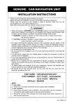
INSTALLATION INSTRUCTIONS
Thank you for purchasing a genuine Mazda accessory.
Before removal and installation, be sure to thoroughly read these instructions.
Please read the contents of this booklet in order to properly install and use the Remote engine
start. Your safety depends on it.
Keep these instructions with your vehicle records for future reference.
WARNING
There are several
WARNING and
CAUTION sections in this booklet concerning safely when
installing or removing the Remote engine start. Always read and follow them in order to prevent injuries,
accidents, and possible damage to the vehicle.
WARNING: Indicates a situation in which serious injury or death could result if the warning
is ignored.
CAUTION: Indicates a situation in which bodily injury or damage to the vehicle could result if the
caution is ignored.
For areas indicating the tightening torque in this instruction manual, tighten to the specified torque using
a torque wrench. For areas in which the tightening torque is indicated inside parentheses ( ), the
tightening torque is indicated as a reference value, however tightening using a torque wrench is not
necessary.
Do not modify the Remote engine start.
Do not install the Remote engine start in any way other than described in the following instructions.
If in any doubt, please ask your Mazda dealer to install the accessory in order to prevent errors in
installation.
If you have any questions about the use of the accessory, ask your Mazda dealer for proper advice
before using it.
Mazda and its suppliers are not responsible for injuries, accidents, and damage to persons and property
that arise from the failure of the dealer or installer to follow these instructions.
To ensure safety and reliability of the work, installation, removal and disposal work must carried out by
an Authorized Mazda Dealership.
Be careful not to lose removed parts, and be sure that they are kept free from scratches, grease or
other dirt.
PART NAME:
VEHICLE:
PART NUMBER:
Remote engine start
MAZDA6
C930 V7 620 (CONTROLLER KIT)
GJR9 V7 630 (HARNESS KIT)
[KD53 V7 629 (Hood Switch)]
NOTE
To the dealer
Please turn over these instructions to the customer after installation.
To the customer
Keep these instructions after installation. The instructions may be necessary
for installing other optional parts or removal of this accessory.
Should the vehicle or this accessory be resold, always leave these instructions
with it for the next owner.
When the remote engine start is removed, clear the remote engine start
information programmed to the vehicle by following the clearing procedure for
the advanced key in the workshop manual. In addition, after clearing, the
advanced key has to be programmed again.
1
ZZ092-00691-00
(ZZ092-00690-00)
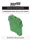
1. PARTS
▼ Installation view
(Sold separately) Hood switch
(Only for vehicle without theft-deterrent or without i-ELOOP system)
RES ECU
TEMP Sensor
Harness
Harness (GND wire)
2
▼ Parts list
Note
Verify that the kit includes all the following parts and that the parts are not dirty, scratched, or damaged.
CONTOROLLER KIT (Part No. C930 V7 620)
Part
Part name
Qty.
Part
Part name
Qty.
Remote Start
Transmitter
(C930 V7 621)
1
RES ECU
1
Double-sided
adhesive tape
1
Owner's manual
1
Part name
Qty.
Part
Part name
TEMP Sensor
Qty.
1
HARNESS KIT (Part No. GJR9 V7 630)
Part
Part name
Qty.
Part
Part
Part name
Qty.
Harness
1
★
Mount base
2
Urethane tape
1
★
Electro tap
1
Tie wrap(White)
【L=200mm】
4
★
Tie wrap(Black)
【L=200mm】
8
Installation
instructions
1
Installation
inspection
sheet
1
★:Parts marked with a star mark are only used on vehicles without theft-deterrent or without i-ELOOP system.
(Sold separately) * The following parts are also necessary for installation.
Note
These parts are not necessary for vehicles with the theft-deterrent or with i-ELOOP system because
the hood switch is already equipped.
Hood Switch (Part No. KD53 V7 629)
Part
Part name
Hood switch
Qty.
1
Part
Part name
Screw
3
Qty.
1
2.BEFORE INSTALLATION
REQUIRED TOOLS
☆Socket wrench
☆Torque wrench
☆Tape-wrapped flathead screwdriver
☆Phillips screwdriver
☆Nipper
☆Pliers
☆Scissors
☆Scale
☆Electrical vinyl tape
☆Soft clean cloth
☆Mat
☆IPA (Isopropyl alcohol)
☆Primer (3M Promoter-4298)
WARNING
When the negative battery
cable is connected during
operation, it may cause
electric shock or other
personal injuries. Disconnect
the negative battery cable
before removal/installation.
When connecting/disconnecting connectors, grasp
the connectors, not the wires.
Otherwise a short, an
accident from poor contact or
fire may occur.
Do not pull the harness with
excessive force. Doing so
can cause a breakage or a
short-related accident, as
well as an electrical short or
fire.
Secure the harness with the
band (part included) so it
doesn’t dangle. If not, it may
cause a short, accident, or
fire.
Wrap protective tape around
screwdrivers and fastener
remover tools to prevent
scratching the vehicle.
Excessive length of tie wrap
may interfere with other parts
and cause damage.
Cut unnecessary part up to
about 5 mm {0.19 in} from
the fixed point.
Put the removed parts and
the parts in the kit on the
protective sheet to prevent
scratches.
CAUTION
Using improper tools may
cause damage and or broken
parts. Use the correct tool for
the job.
WARNING
When removing/installing the parts, park the vehicle on level ground and apply the side brake securely. Be
sure to turn the ignition switch off, otherwise the vehicle can move, causing personal injury or vehicle
damage.
Note
When the negative battery cable is removed, the clock, radio, trip meters and other memories will be erased.
Before performing work, record the content of the memory.
Refer to the Workshop Manual for removal and installation of vehicle parts.
Not following the procedures for removal/installation in the Workshop Manual could result in an accident or
vehicle malfunction.
3.CONNECTION USING ELECTRO-TAP
Branch connection procedure using electro tap
Vehicle wiring harness
Electro tap
CAUTION
Firmly engage the lock part until a click sound is heard.
Vehicle wiring harness
Lock
Vehicle wiring harness
1. Insert the vehicle wiring harness into the electro tap.
2. Fold the electro tap as shown in the figure and lock it.
Lock
3. Insert the harness to the end of the electro tap.
4. Firmly press the electro tap terminal using pliers.
5. Fold the electro tap in the direction of the arrow shown in the
figure and lock it.
Firmly press
using pliers
Harness
Terminal
4
4.CONNECTION DIAGRAM
TYPE A
Insert to empty terminal
(TYPE A and B)
TYPE B
Figure shows connector viewed from harness side.
5
5.PART REMOVAL
CAUTION
Be careful not to damage or lose any parts removed from the vehicle since they will be reused.
Negative battery cable disconnection
1. Set the selector lever to P range.
2. Disconnect the negative battery cable and wrap tape around it
to insulate.
WARNING
When the negative battery cable is connected during
operation, it may cause electric shock or other personal
injuries. Disconnect the negative battery cable before
removal/installation.
Tightening torque : 4.0 - 6.0 N・m
Fastener
Guides
■Parts ① to ④ are only for vehicles without theftdeterrent or without i-ELOOP system
① Seat plate removal
1. Remove the fasteners (2 locations).
2. Lift up the seat plate in the direction of the arrow to detach the
guides (3 locations), and remove the seat plate.
Fastener
Seat plate
Vehicle front
② Hood latch protector removal
Flathead screwdriver
Hood latch protector
1. Insert a tape-wrapped flathead screwdriver into the position
shown in the figure.
2. Move the tape-wrapped flathead screwdriver in the direction of
arrow (1) shown in the figure to press the hood latch protector
tab, and lift the tab up in the direction of arrow (2) and detach
its tab from the hood latch.
3. Detach all the hood latch protector tabs from the hood latch
and remove the hood latch protector.
Vehicle front
: Flathead screwdriver insertion slot
(2)
(1)
Tab
Tab
Hood latch
Hood latch
6
③ Main fuse cover removal
Main fuse cover
1. Detach the main fuse cover tab (1 location), and lift the rear
part of the main fuse cover to remove it.
Tab
Vehicle front
④ Bolt and fastener removal
Bolts
1. Remove the fresh air duct bolts (2 locations).
Bolt tightening torque : 7.8 - 10.8 N・m
Fresh air duct
Vehicle front
Fresh air duct
Fastener A
2. Remove the grille bracket fastener A (1 location).
Grille bracket
Vehicle front
3. Remove the grille bracket fastener B (1 location) and screws (2
locations).
Screw tightening torque : 4.0 - 9.8 N・m
Fastener B
Screw
Vehicle front
Screw
Grille bracket
7
Front scuff plate (Passenger's side) removal
Tab A
Hook B
(1)
Front scuff plate
(2)
(4)
1. Take the shaded area shown in the figure, detach tab A while
pulling the front scuff plate in the direction of the arrow (1)
shown in the figure, then detach the hook B, clip C, and pin D
while pulling in the direction of the arrow (2).
2. Take the shaded area shown in the figure, detach tab E while
pulling the front scuff plate in the direction of the arrow (3)
shown in the figure, then detach the hook F, clip G and pin H
while pulling in the direction of the arrow (4).
Pin D
Clip C
(3)
Pin H
Clip G
Vehicle front
Tab E
Hook F
Hook B
Tab A
Front scuff plate
Pin D
Clip C
Pin H
Clip G
Tab E
Hook F
Cap nut
Clip
Front side trim
(Backside)
Clip
Front side trim (Passenger's side) removal
1. Partially peel back the seaming welt.
2. Remove the cap nut (1 location).
3. Pull the front side trim in the direction of the arrow shown in the
figure and remove it while detaching the clip (1 location).
Front side trim
Seaming welt
Vehicle front
8
Glove compartment removal
1. Push the glove compartment in the direction of the arrow (1)
and hooks A (2 locations).
2. Pull the stay damper in the direction of the arrow (2) shown in
the figure and remove the hook B (1 location).
CAUTION
Hook A
Hook A
Hook A
(1)
If the glove compartment is closed without being joined
to the stay damper, the stay damper may be damaged.
Verify that the stay damper is joined to the glove
compartment before closeing the glove compartment.
(1)
Glove compartment
Stay damper
Vehicle front
(2)
Hook B
Glove compartment
3. Pull down the glove compartment in the direction of the arrow
(3).
4. Pull the glove compartment in the direction of the arrow (4) and
remove it while detaching hooks C (2 locations).
(3)
(4)
Hook C
Vehicle front
9
Dashboard under cover removal
Hook A
(2)
(1)
Hook A
Hook A
Guide C
Pin B
Pin B
(2)
(3)
Vehicle left
Vehicle front
1. Detach hooks A (2 locations) in the direction of arrow (1)
shown in the figure.
2. Pull the dashboard under cover in the direction of arrow (2)
while detaching pins B (2 locations).
3. Remove the dashboard under cover in the direction of the
arrow (3) shown in the figure while detaching the guide C (1
location).
4. Remove the dashboard under cover.
CAUTION
Be careful not to damage guide C when removing hooks
A and pins B. If the dashboard under cover is pulled
forcibly downward, it could damage guide C.
Lower panel (Passenger's side) removal
Lower panel (Passenger's side)
1. Remove bolts A (2 locations).
Bolt tightening torque : 2.0 - 6.0 N・m
Bolts A
Vehicle front
Clip B
Hook C
Pin D
Guide E
Air bag deactivation (PAD) switch
Clips B
Clips B
Hook C
2. Disconnect the passenger air bag deactivation (PAD) switch
connector. (with passenger air bag deactivation (PAD) switch)
3. Pull the passenger's side lower panel in the direction of the
arrow in the order of (1), (2), (3), (4) and remove it while
detaching clips B (2 locations), hook C (1 location), pin D (1
location) and guide E (1 location).
Guide E
(3)
(2)
Clip B
(4)
(1)
Lower panel (Passenger's side)
Pin D
Vehicle front
10
6. HOOD SWITCH INSTALLATION
Note
This procedure is not necessary for vehicles with the theft deterrent or with i-ELOOP system
because the hood switch is already installed.
1. Install the hood switch to the hood latch and secure it using a
screw (1 location).
Hood latch
Screw
Hood switch
Vehicle front
Do no let hood switch
harness contacts bolt.
Mount base and
Tie wrap (Black)
Mount base and
Tie wrap (Black)
2. Hook the hood switch harness to the hood latch and secure it
using a tie wrap (Black) at one location.
3. Install tie wraps (Black) to the mount bases and temporarily
tighten the hood switch harness at two locations.
CAUTION
Do not tighten the tie wrap (Black) so much that the hood
switch harness cannot move.
4. Peel back the tape backings on the back of the mount bases
and affix the mount bases on the shroud member upper at two
locations with the hood switch harness routed as shown in the
figure.
Bolt
Shroud member upper
Tie wrap (Black)
Hood switch harness
Vehicle front
CAUTION
Place the tightening part of the tie wrap (Black) downward
and secure. Otherwise, it may not be possible to re-install
the seat plate.
Tightening
part
5. Pass the hood switch harness between the grille bracket and
the shroud member upper.
Shroud member upper
Hood switch harness
Grille bracket
Tightening
part
Vehicle front
11
Hood switch harness
Tie wrap (Black)
Pass behind vehicle
wiring harness
6. Secure the hood switch harness to the shroud panel using tie
wraps (Black).
7. Route the hood switch harness along the vehicle wiring
harness and secure it using a tie wraps (Black) at one location.
CAUTION
Secure the hood switch harness on the vehicle wiring
harness so that the hood switch harness does not contact
the vehicle edge.
Tie wrap (Black)
Vehicle wiring harness
Tie wrap (Black)
Shroud panel
Vehicle front
Hood switch harness
Vehicle wiring harness
8. Route the hood switch harness along the vehicle wiring
harness and secure it using a tie wrap (Black) at one location.
Pass behind vehicle
wiring harness.
Vehicle front
Tie wrap (Black)
Vehicle wiring harness
18 pin connector
Hood switch harness (White)
9. Insert the hood switch harness (White) terminal to the empty
terminal of the vehicle wiring harness 18 pin connector
(terminal N).
CAUTION
When connecting a terminal to a connector, always refer
to the following <Terminal insertion procedure>.
Connect the harness terminal to the specified signal line
Insert terminal
because a system or vehicle malfunction may occur if it is
connected incorrectly.
Vehicle front
<Terminal insertion procedure>
(b) Insert terminal
[ Vehicle wiring harness 18 pin connector ]
(Connector viewed from wiring harness side)
Terminal
Retainer
(a) Remove retainer
Insert hood switch harness (White)
terminal to empty terminal
Terminal
12
(c) Reinstall retainer
Type A
Vehicle wiring harness
18 pin connector
Hood switch harness (Black)
Vehicles with wiring harness terminal A (Black) shown in
figure (Type A)
10. Branch connect the hood switch harness (Black) to the vehicle
wiring harness 18 pin connector (terminal A (Black)) using an
electro tap, and wrap the electro tap using electrical vinyl tape.
CAUTION
Connect the electro tap to the specified signal line
Electro tap and
electrical vinyl tape
Vehicle front
[Vehicle wiring harness 18 pin connector]
(Connector viewed from wiring harness side)
because a system or vehicle malfunction may occur if it is
connected incorrectly.
For branch connection procedure using electro tap, refer
to [3. CONNECTION USING ELECTRO TAP] on page 4.
Note
If there is no vehicle wiring harness (Black) in the
specified position, do not perform Step 10, go to Step 11.
Terminal:A (Black)
Hood switch harness (Black)
Type B
Vehicle wiring harness
18 pin connector
Hood switch harness (Black)
Vehicles with wiring harness terminal B (Black) shown in
figure (Type B)
11. Branch connect the hood switch harness (Black) to the vehicle
wiring harness 18 pin connector (terminal B (Black)) using an
electro tap, and wrap the electro tap using electrical vinyl tape.
CAUTION
Connect the electro tap to the specified signal line
Electro tap and
electrical vinyl tape
Vehicle front
because a system or vehicle malfunction may occur if it is
connected incorrectly.
For branch connection procedure using electro tap, refer
to [3. CONNECTION USING ELECTRO TAP] on page 4.
[Vehicle wiring harness 18 pin connector]
(Connector viewed from wiring harness side)
Terminal:B (Black)
Hood switch harness (Black)
Hood switch harness
Tie wrap (Black)
Vehicle front
Vehicle wiring harness
12. Route the hood switch harness along the vehicle wiring
harness and secure it using a tie wrap (Black) at one location.
13
7.REMOTE ENGINE START INSTALLATION
110mm
100mm
50mm
ⓐ
ⓑ
ⓒ
Urethane tapeⓐ
1. Cut 1 piece of urethane tape to the dimensions shown in the
figure.
2. Wrap urethane tapeⓐ around the RES ECU.
CAUTION
Because the antenna is retractable, it may cause noise.
Wrap urethane tape from the end of the RES ECU to the
end of the antenna.
RES ECU
Antenna
Double-sided adhesive
tape
3. Degrease the RES ECU using primer, and affix double-sided
adhesive tape.
CAUTION
Use 3M Promoter-4298 for primer.
When degreasing using primer, only apply primer to the
degreased area to prevent other parts from becoming
discolored.
After degreasing using primer, let it dry for 1 min. or more.
Affix double-sided adhesive tape firmly.
RES ECU
4. Connect the TEMP sensor to the harness 2 pin connector.
Harness 2 pin connector
Urethane tapeⓑ
5. Wrap the wiring harness and the TEMP sensor using the
urethane tape ⓑ.
CAUTION
Do not wrap urethane tape around the sensor part of the
TEMP sensor. The sensitivity of the sensor may be
affected if it is wrapped.
100mm
TEMP Sensor
Urethane tapeⓒ
50mm
6. Wrap the fuse of the wiring harness using the urethane tape
ⓒ.
Fuse
14
RES ECU installation position
7. Degrease the RES ECU installation position at the upper back
of the glove compartment (dashboard) using primer, and affix
double-sided adhesive tape of the RES ECU.
CAUTION
Use 3M Promoter-4298 for primer.
When degreasing using primer, only apply primer to the
degreased area to prevent other parts from becoming
discolored.
After degreasing using primer, let it dry for 1 min. or more.
Affix double-sided adhesive tape firmly.
Vehicle front
Align RES ECU with
dashboard line
RES ECU
Dashboard
Vehicle front
Align RES ECU with
end of dashboard
Tie wraps (White)
RES ECU
8. Connect the harness 12 pin connector to the RES ECU.
9. Secure the harness to the vehicle wiring harness using a tie wraps
(White).
Vehicle wiring harness
Vehicle front
Harness 12P Connector
Vehicle wiring harness
2 pin Connector (Option)
Vehicle left
Harness 2 pin connector
Harness
10. Connect the harness 2 pin connector to the vehicle wiring
harness 2 pin Connector (Option).
TEMP Sensor
Vehicle front
15
11. Secure the harness to the vehicle wiring harness using a tie wraps
(White).
Vehicle wiring harness
Harness
Vehicle left
Tie wraps (White)
Vehicle front
Dashboard member
Bolt (Vehicle part)
12. Tighten the dashboard member bolt (vehicle part) together with
the harness (GND wire) which is routed below the glove
compartment.
Bolt
Vehicle front
Harness (GND wire)
Bolt (Vehicle part)
Vehicle front
Dashboard member
16
tightening torque : 8.8-12.7 N・m
8.REINSTALLATION / INSPECTION
1. Reinstall parts in the reverse order of the installation procedure in【PARTS REMOVAL】.
2. After installing the passenger's side lower panel and glove compartment, measure the clearance, and verify that
the measurement value is within the specification shown in the
Lower panel (Passenger's side)
figure.
CAUTION
Glove compartment
If the measurement value is not within the specification
after measuring the clearance between the passenger's
side lower panel and glove compartment, adjust the
passenger's side lower panel to the proper position.
Standard value: 0.5-2.5mm
Standard value: 0.5-2.5mm
3. Refer to "Required servicing after disconnecting/connecting negative battery cable" in the vehicle workshop
manual or the owner's manual to restore the vehicle functions.
4. Perform reinstallation and inspection of the vehicle parts.
5. Register the controller (= RES ECU) with reference to the attached sheets "GENUINE REMOTE ENGINE
START【Parts No. C930 V7 620】Registration Procedure Of the Controller".
17
Date
,
,
VIN.
Person in
charge
Checked
Approved
INSTALLATION
INSPECTION
SHEET
Remote engine start
MAZDA6
C930 V7 620 (CONTROLLER KIT)
GJR9 V7 630 (HARNESS KIT)
KD53 V7 629 (HOOD SWITCH)
Perform the following inspections
WARNING
• Before starting the engine, make sure there are no persons in front of or behind the vehicle, or around the engine
compartment. Otherwise a serious accident could result by the vehicle suddenly moving.
• Do not start the engine in a place such as a garage or other location with poor air ventilation. Otherwise,
poisoning or asphyxiation could result from accumulation of exhaust gas.
• Always set the wheel blocks on level ground before performing the verification.
1. Inspection items after installation
Check
• Verify the fitting between the vehicle part and the installed part, and inspect for damage or dirt.
Check
•
When connecting connectors, verify the connection again to prevent poor connection or mis-connection.
(Insert two times.)
2. Vehicle parts reinstallation
Inspection Parts
Inspection
Inspection Items
Negative battery cable
Torque check
Are the battery cables securely tightened to the
terminals?
Ground
Torque check
Is the ground bolt tightened to the proper torque?
Operation
Have the vehicle’s functions been restored by referring to
“Required servicing after disconnecting/connecting
negative battery cable”, in the vehicle workshop manual
or the owner's manual?
Function restore procedure
after removal/installation of
battery
Check
3. Installation of accessory, operation check
Inspection Parts
RES ECU
―
Inspection
Inspection Items
Registration
Continues on backside
※ The term of validity for this sheet: 3 Years
1. Has the controller been registered by referring
to “GENUINE REMOTE ENGINE START
【 Parts No. C930 V7 620 】 Registration
Procedure Of the Controller”* Note?
―
Check
Inspection Parts
Inspection Items
Remote Start Transmitter
Operation check
Remote Start Transmitter
Operation check
Remote Start Transmitter
Operation check
Inspection
Check
2. Perform the vehicle condition check using the
remote controller, and verify if the “Engine stop”
mark is indicated in the answer back display
and if the error indication “t” is displayed.
3. With all of the following conditions met, start
the engine using the remote controller and
verify that the engine starts.
・ Parking brake is applied
・ Shift lever is in the P position
・ Key is in the vehicle
・ Brake pedal and accelerator pedal are not
depressed
・ Push button start is not pressed
・ All of the doors, the bonnet, and the hood are
closed and locked.
4. Stop the engine using the remote controller and
verify that the engine stops.
※ Troubleshooting note
If a malfunction is verified in the above, refer to the “Troubleshooting manual” *Note issued by Mazda, and
perform troubleshooting.
*Note): Refer to “Troubleshooting manual” on the vehicle accessory Web.