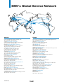
1
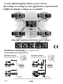
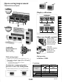
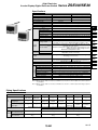
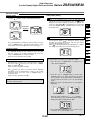
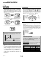
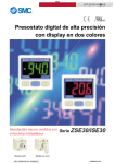
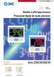
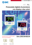
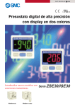
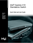
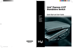
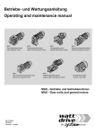
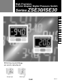
High Precision,
2-color Display Digital Pressure Switch
Series ZSE30/ISE30
ZSE
ISE
PSE
Z
I
SE3
PS
Z
I
SE 12
ZSP
ISA2
IS
ZSM
PF2
IF
Data
With One-touch fittings
are newly introduced.
Straight type
Elbow type
16-2-1
2-color digital display allows you to choose
the setting according to your application requirements.
4 different display settings are available.
∗ This photo shows 2
display
colors
simultaneously for
product presentation
purposes. In actual
application, only one
color is displayed at a
time.
Abnormal conditions can be detected at a glance!
PRESSURE
PRESSURE
kPa
OUT
OUT
SET
PRESSURE
kPa
OUT
SET
PRESSURE
kPa
PRESSURE
kPa
OUT
SET
kPa
OUT
SET
SET
With One-touch fitting (ø4, ø6, ø5/32", ø1/4")
Reduced dimensions in piping direction
17.8 mm reduction∗
12.4 mm reduction∗
Straight type
Elbow type
14.4
22.4
17.8 mm
32.2
12.4 mm
34.8
KQ2H06-M5
KQ2L06-M5
∗ Comparison when One-touch fittings (KQ2H06-M5 / KQ2L06-M5) are connected to the piping ports (M5 x 0.8)
16-2-2
Space-saving improvement
Economical use of space
Old Model
ZSE4E
ISE4E
Each displa
y required
its own pa
Display calibration
nel openin
g.
Old Model
40
ZSE
ISE
PSE
Z
I
126
PS
New Model
New Model
ZSE30
ISE30
SE3
Z
I
Just one p
anel openin
g is
required fo
r st
displays, w ackable
hich can b
e
mounted e
ithe
or vertically r horizontally
.
SE 12
ZSP
ISA2
This function allows uniformity in the numbers displayed.
IS
34.5
ZSM
More user-friendly controls
PF2
Raised rubber
button controls are
clearly set apart,
simple to operate,
soft to the touch.
IF
103.5
Compact p
rofile
Plug-type
connectors take the
burden out of
wiring work and
maintenance.
Applicable
panel thickness is
up to 6 mm.
(Panel mounting)
High-precision
With analog output
resolution: 1/1000
In addition to the conventional voltage output type (1 to 5 V)
Current output type (4 to 20 mA)
is now available.
• Convenient when longer wiring is required
• Excellent noise resistance
Variations
Vacuum/Low pressure
ZSE30
Switches for vacuum and positive
pressure can be easily distinguished.
The different display panel frame colors easily tell them apart.
Vacuum/Low pressure (ZSE30)
Blue
Positive pressure (ISE30)
Gray
1 MPa
100 kPa
Rated pressure
range
Positive pressure
ISE30
0
0
–100 kPa
Setting/Display resolution
Output
Switch output
0.2 kPa
0.001 MPa
NPN/PNP open collector (1 output)
Analog output Voltage output: 1 to 5 V; Current output: 4 to 20 mA
Current consumption
45 mA or less (70 mA or less for current output)
Option
Panel mount/Bracket
16-2-3
Data
®
High Precision,
2-color Display Digital Pressure Switch
Series ZSE30/ISE30
How to Order
Option 1
Without lead wire
Nil
Lead wire with connector
(Lead wire length: 2 m)
L
For positive pressure
ISE30
01
25
M
For vacuum/low pressure
ZSE30
01
25
M
Option 2
Piping specifications
01
R 1/8
(With M5 female thread)
T1
NPT 1/8
(With M5 female thread)
C4H
ø4 One-touch fitting
ø5/32" One-touch fiting
C6H
ø6 One-touch fitting
N7H
ø1/4" One-touch fitting
C4L
ø4 One-touch fitting
ø5/32" One-touch fitting
C6L
ø6 One-touch fitting
N7L
ø1/4" One-touch fitting
Nil
None
Bracket
A
Straight type
Output specifications
25
NPN output
65
PNP output
26
1 to 5 V output
28 4 to 20 mA output
Panel mount
B
Elbow type
Panel mount adapter +
Front protective
cover
D
Option Part No.
When optional parts are required separately, use the following part
numbers to place an order.
Option
Lead wire with connector
Part no.
Note
ZS-27-A
Bracket
ZS-27-B
Lead wire length: 2 m
With mounting screws
(M3 x 5L: 2 pcs.)
With M3 x 8L (2 pcs.)
Panel mount adapter
ZS-27-C
Panel mount adater + Front protective cover ZS-27-D
16-2-4
With M3 x 8L (2 pcs.)
Unit specifications
Nil
With unit switching function
M
Fixed SI unit (International System of Units) Note)
Note) Fixed unit:
For vacuum/Low pressure: kPA
For positive pressure: MPa
High Precision,
2-color Display Digital Pressure Switch
Series
ZSE30/ISE30
Specifications
ZSE30 (Vacuum/Low pressure)
ISE30 (Positive pressure)
Rated pressure range
–100.0 to 100.0 kPa
0.000 to 1.000 MPa
Regulating pressure range
–101.0 to 101.0 kPa
–0.100 to 1.000 MPa
Proof pressure
500 kPa
1.5 MPa
Min. regulating unit
0.2 kPa
0.001 MPa
Fluid
Air, Inert gas, Non-flammable gas
Power supply voltage
12 to 24 VDC, Ripple (p-p) 10% or less (With power supply polarity protection)
Current consumption
45 mA or less (at no load)
Switch output Note 1)
NPN or PNP open collector output: 1 output
Max. load current
80 mA
Max. applied voltage
30 V (With NPN output)
Residual voltage
1 V or less (With load current of 80 mA)
Response time
2.5 ms or less (Response time selections with anti-chattering function: 20, 160, 640, 1280 ms)
Short circuit protection
Yes
Repeatability
±0.2% F.S. ±2 digit or less
±0.2% F.S. ±1 digit or less
Note 2)
Output voltage: 1 to 5 V ±2.5% F.S. or less (With rated pressure range)
Linearity: ±1% F.S. or less, Output impedance: Approx. 1 kΩ
Output current: 4 to 20 mA ±2.5% F.S. or less (With rated pressure range)
Linearity: ±1% F.S. or less
Maximum load impedance: 300 Ω with power supply voltage of 12 V;
600 Ω with power supply voltage of 24 V
Minimum load impedance: 50 Ω
Voltage output
Analog
output
Hysteresis
Note 3)
Current output
Hysteresis mode
Window comparator mode
Display
PS
Z
I
SE 12
ZSP
ISA2
ZSM
Environmental
resistance
Piping Specifications
Weight
SE3
3 1/2 digit, 7-segment indicator, 2-color display (Red and green)
Sampling cycle: 5 times/s
Note 1) When switch output is selected, analog output is not available.
Note 2) When voltage output is selected, a simultaneous selection of switch output and current output is
not available.
Note 3) When current output is selected, a simultaneous selection of switch output and voltage output is
not available.
01
T1
C4H
C6H
N7H
C4L
C6L
N7L
R 1/8
M5 x 0.8
NPT 1/8
M5 x 0.8
—
—
—
—
—
—
One-touch fitting
Straight type
—
—
ø4 mm
ø5/32 inch
ø6 mm
ø1/4 inch
—
—
—
One-touch fitting
Elbow type
—
—
—
—
—
ø4 mm
ø5/32 inch
ø6 mm
ø1/4 inch
Wetted part material
Z
I
IS
±2% F.S. ±2 digit
±2% F.S. ±1 digit
(at 25°C ambient temperature) (at 25°C ambient temperature)
Light up when output is ON (Green)
Indicator light
±2% F.S. or less (based on 25°C)
Temperature characteristics
IP40
Enclosure
Operating temperature range Operating: 0 to 50°C, Stored: –10 to 60°C (No freezing or condensation)
Operating and stored: 35 to 85% RH (No condensation)
Operating humidity range
1000 VAC for 1 min. between live parts and enclosure
Withstand voltage
50 MΩ or more between live parts and enclosure (at 500 VDC)
Insulation resistance
10 to 150 Hz, 1.5 mm or 20 m/s2 amplitude in X, Y, Z directions for 2 hours each
Vibration resistance
100 m/s2 in X, Y, Z directions 3 times each
Impact resistance
Compliant with CE Marking and UL (CSA) standards
Standard
Port
size
PSE
Adjustable (can be set from 0)
Display accuracy
Part
ZSE
ISE
Sensor pressure receiving area: Silicon, Piping port: C3602 (Electroless nickel plated), O-ring: HNBR
O-ring: NBR, fitting: PBT
O-ring: NBR
With lead wire
with connector (2 m)
81 g
76 g
78 g
Without lead wire
with connector
43 g
38 g
40 g
16-2-5
PF2
IF
Data
Series
ZSE30/ISE30
Setting
Pressure setting
Press the SET button.
Enter the set value of the
pressure to perform switch
output.
Measuring
mode
Press the SET button.
Initial setting
Set the output type, response
time, and display color
switching.
Press the SET button
and hold for 2 sec. or longer.
Measuring mode
Detects and displays the pressure and
performs switch operations. Other functions
such as the value clear function can be set
according to the application purpose.
Press the SET button.
Initial Setting
Initial setting mode
Press and hold the SET button for 2 seconds or longer.
Display monitor will be per Figure A below, and the switch
will now be in the display color setting mode.
PRESSURE
3. Output type setting
The type of switch output can be set arbitrarily.
While the current output type is displayed, press the
DOWN button to switch between normally open
and
normally closed
.
PRESSURE
PRESSURE
OUT
Figure A
OUT
OUT
If the unit specification indicated at the time of ordering is “M”,
the fixed SI unit will be used. If it is Nil, refer to “Unit Switching
Function” on page 16-2-8.
Normally closed
Normally open
Press the SET button to set the output type and proceed to
the response time setting.
4. Response time setting
1. Display color setting
Select the color for LCD display.
Press the UP or DOWN button to choose a display color.
PRESSURE
PRESSURE
The switch output response time can be set arbitrarily.
Chattering can be prevented with a response time setting.
While the current response time is displayed, press the UP
or DOWN button to select a new response time.
PRESSURE
OUT
PRESSURE
PRESSURE
OUT
ON: Red
ON: Green
PRESSURE
OUT
PRESSURE
OUT
2.5 ms
OUT
20 ms
160 ms
PRESSURE
OUT
ON/OFF: Red
ON/OFF: Green
Press the SET button to set the color and proceed to the
operating mode setting.
If the analog output is set, press the UP or DOWN button
and select the desired display color from
(Green) or
(Red). Press the SET button to exit this mode and return to
the measuring mode.
2. Operating mode setting
This mode will let you select the switch operating mode.
While the current operating mode is displayed, press the
UP or DOWN button to select a newly desired operating
PRESSURE
PRESSURE
OUT
OUT
640 ms
1280 ms
Press the SET button to set the response time and proceed
to the auto preset setting.
If the operating mode is the window comparator mode, press
the SET button to return to the measuring mode.
5. Auto preset setting
This function stores the measuring pressure that is set
during the auto preset mode as a basic value.
While the current setting is displayed, press the UP or
DOWN button to select it as an auto preset setting.
PRESSURE
PRESSURE
OUT
OUT
Hysteresis mode
ON
Window comparator mode
ON
OFF
ON
OFF
P1
ON
OFF
n1
(Standard: Factory setting) (Reversed)
Hysteresis Hysteresis
(H)
(H)
Hysteresis Hysteresis
(H)
(H)
Hysteresis
(H)
Hysteresis
(H)
OFF
P1
P2
(Standard: Factory setting)
n1
n2
(Reversed)
Press the SET button to set the mode and proceed to the
output type setting.
16-2-6
PRESSURE
OUT
OUT
OUT
Manual
Auto
Press the SET button to set the auto preset and return to the
measuring mode.
High Precision,
2-color Display Digital Pressure Switch
Series
ZSE30/ISE30
Pressure setting
Auto preset setting
Manual setting
Press the SET button in the measuring mode to display the
set value.
and the current set value blink alternately.
PRESSURE
OUT
Normally Open
Alternately
displayed
PRESSURE
1. Auto preset preparation mode
While in the measuring mode, press the SET button to
activate the auto preset preparation mode, and
will be
displayed. Proceed to prepare the devices to perform the
pressure setting. While
is still displayed, press both the
UP and DOWN buttons simultaneously to return to the
measuring mode.
PRESSURE
OUT
Press the SET button to display the next set value. Press the
UP or DOWN button to change the value. (Refer to “How
to Set Value” on the lower right hand corner of this page.)
2. Auto preset setting
Press the SET button to activate the mode to execute auto
preset functions. When
is displayed, start the system
operation and change the pressure. The set value will be
automatically detected and stored.
While
is still displayed, press the SET button to complete
the setting and return to the normal measuring mode.
Hysteresis mode
Window comparator mode
In this mode, P2 and the current set value are displayed
alternately after setting P1. Press the SET button to display
the next set value ( : hysteresis). Press the UP or DOWN
button to change the value.
(Refer to “How to Set Value” at right.)
Next,
and the set value for hysteresis will be displayed
alternately. Press the SET button to return to the normal
measuring mode. Press the UP or DOWN button to
change the value.
(Refer to “How to Set Value” at right.)
Pressure set value can be verified without holding or stopping
the switch output operation.
Z
I
SE 12
ZSP
ISA2
IS
PRESSURE
In this mode, hysteresis (H) and the set value for hysteresis
are displayed alternately after setting P1. Press the SET
button to return to the normal measuring mode. Press the
UP or DOWN button to change the value.
(Refer to “How to Set Value” below right.)
SE3
PS
OUT
Normally Closed
PSE
Z
I
PRESSURE
OUT
ZSE
ISE
ZSM
PF2
OUT
IF
How to Set Value
To enter a value such as the one for pressure setting:
1. Press the UP or DOWN button to change the set
value. The first digit blinks.
1st digit
2. Press the UP or DOWN button to set the value
arbitrarily. (If there is no button operation for more than
10 seconds, the current value will be automatically set
and the function will return to the set value display
mode.)
3. With every push of the SET button, the next (higher)
digit blinks.
2nd digit
3rd digit
When the left-most digit is zero, “ ” or “ ” will blink.
If the SET button is pressed while the left-most digit is
blinking, the right-most digit will now blink.
4. Press and hold the SET button for 1 second or longer
to return to the set value display mode.
16-2-7
Data
Series
ZSE30/ISE30
Setting
Function setting
Display calibration
Key lock function
During measuring mode, press the SET and DOWN buttons
simultaneously and hold for 2 seconds or longer.
and
current measured value will be displayed.
Press the UP or DOWN button to change the set value. If
there is no button operation for more than 2 seconds after
changing the set value, the display mode returns to displaying
and the current measured value.
PRESSURE
Alternately
displayed
Selection of lock and unlock
OUT
OUT
Current measured value
Press the SET button to display the adjusted value (percent).
The adjusted value and
will be alternately displayed.
PRESSURE
Measuring mode
Press the SET button
SET
and hold for 4 sec.
or longer
Lock
Unlock
Measuring mode
PRESSURE
This function prevents incorrect operations such as changing
the set value accidentally. Press the SET button and hold for 4
seconds or longer to display the current
or
setting.
Press the UP or DOWN button to select the setting and set
this function with the SET button. Use the
mode to avoid
accidental button operation. To release a key lock function,
press the SET button and hold for 4 seconds or longer to
display the current setting, and select the
mode.
PRESSURE
Alternately
displayed
Zero out (Zero ADJ) function
OUT
OUT
Adjusted value
(Percent)
Press the SET button to return to the normal measuring mode.
PRESSURE
This function clears and resets the displayed value as long as
the measuring pressure is within ±70 digits of the atmospheric
pressure.
(Due to individual product differences, the setting range varies
±10% F.S.)
This function is effective in detecting pressure fluctuations that
exceed a certain amount without being affected by the supply
pressure. Press and hold the UP and DOWN buttons
simultaneously to reset the display. Release the buttons to
return to the measuring mode.
OUT
Displayed pressure value
This function eliminates slight differences in the output values and
allows uniformity in the numbers displayed.
Displayed values of the pressure sensor can be calibrated to within
±5% for Series ISE and ±2.5% for Series ZSE.
±5% R.D.
(±2.5% R.D.)
Unit Conversion Function
+
0 Applied pressure
: Factory setting display value
set prior to shipment
: Display calibration range
Note) When the display calibration function is used, the regulating pressure
value may change ±1 digit.
Peak/Bottom hold function
This function constantly detects and updates the maximum
and minimum pressure values and allows to hold the display
value.
To use a peak hold function, press and hold the UP button
for 1 second or longer. The maximum pressure value is held
and blinks repeatedly. Press and hold the UP button again
for 1 second or longer to release this function and return to
the measuring mode.
To use a bottom hold function, press the DOWN button for 1
second or longer. The minimum pressure value is held and
blinks repeatedly. Press and hold DOWN button again for 1
second or longer to release this function and return to the
measuring mode.
16-2-8
Measuring mode
+
Press and hold for
1 second or longer.
When not selecting “M” for unit specification
Desired display unit can be selected.
Press the UP or DOWN button to switch the unit, and
the set value is automatically converted.
The conversion order is: PA⇔GF⇔bAr⇔PSi⇔inH⇔mmH
Press the SET button to set the unit and proceed to the
display color setting.
For vacuum/low pressure Pa⇔kgf/cm2⇔bar⇔psi⇔inchHg⇔mmHg
For positive pressure MPa⇔kgf/cm2⇔bar⇔psi
Indication of Units
Displayed unit
Pa
kgf/cm2
bar
psi
mmHg
inchHg
ISE30
ZSE30
0.001 MPa
0.01
0.01
0.2
—
—
0.2 kPa
0.002
0.002
0.05
2
0.2
High Precision,
2-color Display Digital Pressure Switch
Series
ZSE30/ISE30
Description
Indication light (Green)
LCD display
Displays the switch operation status.
PRESSURE
MPa
UP button
OUT
SET
Use this button to change the
mode or increase the ON/OFF set
value. It also allows you to switch
to the peak value display mode.
SET button
Use this button to switch the
mode and set the set value.
Displays the current pressure
condition,
setting
mode
conditions, selected display unit,
and error codes. A display color
type can be selected from either a
single color display with red or
green, or 2-color display in which
green and red are switched
according to the output.
ZSE
ISE
PSE
DOWN button
Z
I
Use this button to change the
mode or decrease the ON/OFF
set value. It also allows you to
switch to the bottom value display
mode.
SE3
PS
Z
I
SE 12
ZSP
ISA2
Error Correction
Example of Internal Circuit and Wiring
Take the following corrective solutions when errors occur.
-25
NPN open collector output
Maximum 30 V, 80 mA
Residual voltage:
1 V or less
Solution
overcurrent
error
Shut off the power
supply. After eliminating
the output factor that
Load current of switch
output is more than 80 mA. caused the excess
current, turn the power
supply back on.
Residual
pressure
error
Pressure is applied during the
zero out operation as follows:
When the switch for positive
pressure is used: ±0.071 MPa
or more.
When the switch positive
pressure is used:
±7.1 kPa or more.
After displaying for 3 seconds,
it will return to the measuring
mode. Due to the individual
product difference, the setting
range varies ±10% F.S.
PF2
Brown DC(+)
Main circuit
Condition
ZSM
IF
Load
+
Black OUT
–
12
to
24 VDC
Blue DC(–)
Bring the pressure
back to atmospheric
pressure and try
using the zero out
function.
-26
Analog output type
1 to 5 V (±2.5% F.S.)
Output impedance:
1 kΩ
Brown DC(+)
Main circuit
Error
LCD
description display
IS
Black OUT
(Analog output)
Load
+
–
12
to
24 VDC
Blue DC(–)
Supply pressure is below
the minimum regulating
pressure.
Reduce/Increase
supply pressure to
within the regulating
pressure range.
-28
Analog output type
4 to 20 mA (±2.5% F.S.)
Maximum load impedance:
Power supply voltage 12 V: 300 Ω
Power supply voltage 24 V: 600 Ω
Minimum load impedance: 50 Ω
Internal data error
Brown DC(+)
Main circuit
Applied
pressure
error
Supply pressure exceeds
the maximum regulating
pressure.
Black OUT
(Analog output)
Load
12
to
– 24 VDC
+
Blue DC(–)
System
error
Internal data error
Internal data error
Shut off the power
supply. Turn the
power supply back
on.
If the power should
not come back on,
please contact SMC
for an inspection.
-65
PNP open collector
Maximum 80 mA
Brown DC(+)
Main circuit
Internal data error
12
to
– 24 VDC
+
Black OUT
Load
Blue DC(–)
16-2-9
Data
Series
ZSE30/ISE30
Dimensions
30
25
8
9.5
Lead wire
with connector
3.6
M5 x 0.8
Wi
dth
SET
01: R 1/8
T1: NPT 1/8
C
øB
øB
Straight
Elbow
With One-touch fitting
15
10
42.5
With bracket
4.2
sf
lat
s1
2
A
A
3
22
30
20
20
25
1.8
30
45
SMC
16-2-10
ac
ros
1.5
35
20 ±0.1
SMC
OUT
2-M3 x 0.5
Thread depth 4
MPa
10
PRESSURE
20 ±0.1
35
One-touch fitting
size
ø4, ø5/32"
ø6
ø1/4"
Straight
A
B
14.4
11.2
(mm)
Elbow
C
B
A
10.4 18
20
22.4 12.8 20
22.8 13.2 20.5
High Precision,
2-color Display Digital Pressure Switch
Series
ZSE30/ISE30
Dimensions
Panel mount
ZSE
ISE
PSE
7.2
17.8
8
Z
I
9.5
34.5
Z
I
R4
MPa
R4
ZSP
ISA2
SET
SE 12
.5
.5
OUT
SE3
PS
21
PRESSURE
47.8
MADE IN JAPAN
IS
8.75
Panel thickness 0.5 to 6
ZSM
PF2
IF
Panel mount adapter + Front protective cover
Data
42.4
11
17.8
8
9.5
34.5
Panel thickness 0.5 to 6
16-2-11
Series
ZSE30/ISE30
Dimensions
Panel fitting dimension
Multiple (2 pcs. or more) horizontal mounting
PRESSURE
PRESSURE
MPa
OUT
SET
SET
31 x n pcs. + 3.5 x (n pcs. – 1)
24 and up
0
31 –0.4
0
31 –0.4
MADE IN JAPAN
MADE IN JAPAN
MADE IN JAPAN
Multiple (2 pcs. or more) vertical mounting
0
31–0.4
PRESSURE
24 and up
MPa
PRESSURE
SET
MPa
OUT
SET
PRESSURE
MPa
31 x n pcs. + 3.5 x (n pcs. – 1)
OUT
MADE IN JAPAN
MADE IN JAPAN
OUT
16-2-12
SET
MPa
OUT
SET
OUT
PRESSURE
MPa
MADE IN JAPAN
1-pc. mounting
Series ZSE30/ISE30
Specific Product Precautions 1
Be sure to read before handling.
Handling
Operating Environment
1. Do not drop, bump, or apply excessive
impacts (980 m/s2) while handling. Although
the body of the sensor may not be damaged,
the internal parts of the sensor could be
damaged and lead to a malfunction.
2. The tensile strength of the cord is 35 N.
Applying a greater pulling force on it can
cause a malfunction. When handling, hold
the body of the sensor––do not dangle it
from the cord.
3. Do not exceed the screw-in torque of 7 to 9
N⋅m when installing piping. Exceeding this
value may cause malfunctioning of the
sensor.
4. Do not use pressure sensors with corrosive
and/or flammable gases or liquids.
5. Allow a sufficient margin of tube length in
piping in order to prevent application of
torsional, tensile or moment load to the
tubes and fittings.
6. When a brand of tubing other than SMC is
used, make sure that the tolerance of the
tube’s O.D. satisfies the following
specifications.
1. Our pressure switches are CE marked;
however, they are not equipped with surge
protection against lightning. Lightning surge
countermeasures should be applied directly
to system components as necessary.
2. Our pressure switches do not have an
explosion proof rating. Never use in the
presence of an explosive gas as this may
cause a serious explosion.
3. Do not use in an environment where static
electricity can cause problems, otherwise
system failure or malfunction may result.
Warning
Warning
1) Nylon tubing: ±0.1 mm or less
2) Soft nylon tubing: ±0.1 mm or less
3) Polyurethane tubing: +0.15 mm or less, –0.2 mm or less
7. The applicable fluid is air. Please consult
with SMC if the switch is to be used with
other types of fluids.
Connection
Warning
1. Incorrect wiring can damage the switch and
cause a malfunction or erroneous switch
output. Connections should be done while
the power is turned off.
2. Do not attempt to insert or pull the pressure
sensor or its connector when the power is
on. A switch output malfunction may occur.
3. Wire separately from power lines and high
voltage lines, avoiding wiring in the same
conduit with these lines. Malfunctions may
occur due to noise from these other lines.
4. If a commercial switching regulator is used,
make sure that the F.G. terminal is
grounded.
ZSE
ISE
PSE
Z
I
SE3
PS
Z
I
SE 12
ZSP
ISA2
IS
Mounting
ZSM
Caution
PF2
1. Mounting with panel mount adapter
IF
Data
Panel mount
adapter
Panel mount
adapter
Panel
To release push the
clips outward as shown
on the picture, and pull
back towards you.
Claw
2. Mounting with bracket
Mount a bracket to the body using two M3 x 5L mounting
screws and install on piping with hexagon socket head cap
screws. The switch can be installed horizontally depending on
the installation location.
Mounting screw
M3 x 5L
Bracket
Tightening torque for bracket mounting
screw should be 0.5 to 0.7 N⋅m.
16-2-13
Series
ZSE30/ISE30
Specific Product Precautions 2
Be sure to read before handling.
Connection/Removal of Connector
Piping
• To connect the connector, insert it straight while
pinching the lever, and then push the lever into the jack
of the housing and lock it.
• To remove the connector, pull it straight out while
applying pressure with your thumb to the lever and
unhooking it from the jack.
• Cut the tube perpendicularly.
• Hold the tube and insert it into the One-touch fitting
carefully and securely all the way to the bottom.
Tube
Lever
DC polarity indicator
Lead wire (Brown)
One-touch fitting
Lead wire (Black)
Lead wire (Blue)
• Do not attempt to insert or pull the pressure sensor or
its connector when the power is on. A switch output
malfunction may occur.
Regulating Pressure Range and Rated Pressure Range
Caution
Set the pressure within the rated pressure range.
The regulating pressure range is the range of pressure that is possible in setting.
The rated pressure range is the range of pressure that satisfies the specifications (accuracy, linearity, etc.) on the sensor.
Although it is possible to set a value outside the rated pressure range, the specifications will not be guaranteed even if the value stays
within the regulating pressure range.
Pressure range
Switch
–100 kPa
For vacuum/
low pressure
ZSE30
For positive
pressure
ISE30
0
–100 kPa
1 MPa
101 kPa
0
(–0.1 MPa)
500 kPa
100 kPa
–101 kPa
–100 kPa
100 kPa
1 MPa
1 MPa
Rated pressure range of switch
Regulating pressure range of switch
16-2-14
Safety Instructions
These safety instructions are intended to prevent a hazardous situation and/or
equipment damage. These instructions indicate the level of potential hazard by labels of
"Caution", "Warning" or "Danger". To ensure safety, be sure to observe ISO 4414 Note 1),
JIS B 8370 Note 2) and other safety practices.
Caution : Operator error could result in injury or equipment damage.
Warning : Operator error could result in serious injury or loss of life.
Danger :
In extreme conditions, there is a possible result of serious injury or loss of life.
Note 1) ISO 4414: Pneumatic fluid power--General rules relating to systems.
Note 2) JIS B 8370: General Rules for Pneumatic Equipment
Warning
1. The compatibility of pneumatic equipment is the responsibility of the person
who designs the pneumatic system or decides its specifications.
Since the products specified here are used in various operating conditions, their compatibility for the
specific pneumatic system must be based on specifications or after analysis and/or tests to meet your
specific requirements. The expected performance and safety assurance will be the responsibility of the
person who has determined the compatibility of the system. This person should continuously review
the suitability of all items specified, referring to the latest catalog information with a view to giving due
consideration to any possibility of equipment failure when configuring a system.
2. Only trained personnel should operate pneumatically operated machinery
and equipment.
Compressed air can be dangerous if an operator is unfamiliar with it. Assembly, handling or repair of
pneumatic systems should be performed by trained and experienced operators.
3. Do not service machinery/equipment or attempt to remove components until
safety is confirmed.
1. Inspection and maintenance of machinery/equipment should only be performed once measures to
prevent falling or runaway of the driver objects have been confirmed.
2. When equipment is to be removed, confirm the safety process as mentioned above. Cut the supply
pressure for this equipment and exhaust all residual compressed air in the system.
3. Before machinery/equipment is restarted, take measures to prevent shooting-out of cylinder piston
rod, etc.
4. Contact SMC if the product is to be used in any of the following conditions:
1. Conditions and environments beyond the given specifications, or if product is used outdoors.
2. Installation on equipment in conjunction with atomic energy, railway, air navigation, vehicles,
medical equipment, food and beverages, recreation equipment, emergency stop circuits, clutch and
brake circuits in press applications, or safety equipment.
3. An application which has the possibility of having negative effects on people, property, or animals,
requiring special safety analysis.
16-14-3
Common Precautions
Be sure to read before handling.
For detailed precautions on every series, refer to main text.
Selection
Warning
1. Confirm the specifications.
Products represented in this catalog are designed for use in
compressed air appllications only (including vacuum), unless
otherwise indicated.
Do not use the product outside their design parameters.
Please contact SMC when using the products in applications
other than compressed air (including vacuum).
Mounting
Warning
1. Instruction manual
Install the products and operate them only after reading the
instruction manual carefully and understanding its contents.
Also keep the manual where it can be referred to as
necessary.
4. Use clean air
If the compressed air supply is contaminated with chemicals,
cynthetic materials, corrosive gas, etc., it may lead to break
down or malfunction.
Operating Environment
Warning
1. Do not use in environments where the product
is directly exposed to corrosive gases,
chemicals, salt water, water or steam.
2. Do not expose the product to direct sunlight
for an extended period of time.
3. Do not use in a place subject to heavy
vibrations and/or shocks.
4. Do not mount the product in locations where it
is exposed to radiant heat.
Maintenance
2. Securing the space for maintenance
When installing the products, please allow access for
maintenance.
3. Tightening torque
When installing the products, please follow the listed torque
specifications.
Piping
Caution
1. Before piping
Make sure that all debris, cutting oil, dust, etc, are removed
from the piping.
2. Wrapping of pipe tape
When screwing piping or fittings into ports, ensure that chips
from the pipe threads or sealing material do not get inside the
piping. Also, when the pipe tape is used, leave 1.5 to 2 thread
ridges exposed at the end of the threads.
Air Supply
Warning
1. Operating fluid
Please consult with SMC when using the product in
applications other than compressed air (including vacuum).
Regarding products for general fluid, please ask SMC about
applicable fluids.
2. Install an air dryer, aftercooler, etc.
Excessive condensate in a compressed air system may cause
valves and other pneumatic equipment to malfunction.
Installation of an air dryer, after cooler etc. is recommended.
3. Drain flushing
If condensate in the drain bowl is not emptied on a regular
basis, the bowl will over flow and allow the condensate to
enter the compressed air lines.
If the drain bowl is difficult to check and remove, it is
recommended that a drain bowl with the auto-drain option be
installed.
For compressed air quality, refer to “Air Preparation
Equipment” catalog.
16-14-4
Warning
1. Maintenance procedures are outlined in the
operation manual.
Not following proper procedures could cause the product to
malfunction and could lead to damage to the equipment or
machine.
2. Maintenance work
If handled improperly, compressed air can be dangerous.
Assembly, handling and repair of pneumatic systems should
be performed by qualified personnel only.
3. Drain flushing
Remove drainage from air filters regularly. (Refer to the
specifications.)
4. Shut-down before maintenance
Before attempting any kind of maintenance make sure the
supply pressure is shut of and all residual air pressure is
released from the system to be worked on.
5. Start-up after maintenance and inspection
Apply operating pressure and power to the equipment and
check for proper operation and possible air leaks. If operation
is abnormal, please verify product set-up parameters.
6. Do not make any modifications to be product.
Do not take the product apart.
Quality Assurance Information
(ISO 9001, ISO 14001)
Reliable quality of products in the global market
To enable our customers throughout
the world to use our products with
even greater confidence, SMC has
obtained certification for international
standards “ISO 9001” and “ISO
14001”, and created a complete
structure for quality assurance and
environmental
controls.
SMC
products pursue to meet its
customers’ expectations while also
considering company’s contribution in
society.
SMC’s quality control system
Make customers our
first priority, offering
them reliable and
friendly service.
Produce the highest
quality with the
participation of all
employees.
Create new
products using the
latest technology,
and offer the finest
products in a
timely manner.
Quality policies
Market research
Product planning
After service
Sales coordination
Quality management system
ISO 9001
This is an international standard for quality control
and quality assurance. SMC has obtained a large
number of certifications in Japan and overseas,
providing assurance to our customers throughout
the world.
Quality system
education
Training of
suppliers
Research
Education
Design
Training
Development
Production
New product evaluation
Reliability design
Reliability testing
New technical
development
Process control
Inspection, testing, etc.
Initial production control
Quality control activities
Environmental management system
ISO 14001
This is an international standard related to
environmental management systems and
environmental inspections. While promoting
environmentally friendly automation technology,
SMC is also making diligent efforts to preserve
the environment.
16-14-5
SMC Product Conforming to Inter
SMC products complying with EN/ISO, CSA/UL standards are supporting
CE Mark
The CE mark indicates that machines and components meet essential requirements of all the EC Directives
applied.
It has been obligatory to apply CE marks indicating conformity with EC Directives when machines and
components are exported to the member Nations of the EU.
Once “A manufacturer himself” declares a product to be safe by means of CE marking (declaration of
conformity by manufacturer), free distribution inside the member Nations of the EU is permissible.
CE Mark
SMC provides CE marking to products to which EMC and Low Voltage Directives have been applied, in
accordance with CETOP (European hydraulics and pneumatics committee) guide lines.
As of February 1998, the following 18 countries will be obliged to conform to CE mark legislation
Iceland, Ireland, United Kingdom, Italy, Austria, Netherlands, Greece, Liechtenstein, Sweden, Spain, Denmark,
Germany, Norway, Finland, France, Belgium, Portugal, Luxembourg
EC Directives and Pneumatic Components
• Machinery Directive
The Machinery Directive contains essential health and safety requirements for machinery, as applied to
industrial machines e.g. machine tools, injection molding machines and automatic machines. Pneumatic
equipment is not specified in Machinery Directive. However, the use of SMC products that are certified as
conforming to EN Standards, allows customers to simplify preparation work of the Technical Construction File
required for a Declaration of Conformity.
• Electromagnetic Compatibility (EMC) Directive
The EMC Directive specifies electromagnetic compatibility. Equipment which may generate electromagnetic
interference or whose function may be compromised by electromagnetic interference is required to be immune
to electromagnetic affects (EMS/immunity) without emitting excessive electromagnetic affects (EMI/emission).
• Low Voltage Directive
This directive is applied to products, which operate above 50 VAC to 1000 VAC and 75 VDC to 1500 VDC
operating voltage, and require electrical safety measures to be introduced.
• Simple Pressure Vessels Directive
This directive is applied to welded vessels whose maximum operating pressure (PS) and volume of vessel (V)
exceed 50 bar/L. Such vessels require EC type examination and then CE marking.
16-14-6
SMC Product Conforming to International Standards
national Standards
you to comply with EC directives and CSA/UL standards.
Mark of compliance
for CSA/UL
Mark of compliance
for CSA
CSA Standards & UL Standards
UL and CSA standards have been applied in North America (U.S.A. and Canada) symbolizing safety of electric
products, and are defined to mainly prevent danger from electric shock or fire, resulting from trouble with
electric products. Both UL and CSA standards are acknowledged in North America as the first class certifying
body. They have a long experience and ability for issuing product safety certificate. Products approved by CSA
or UL standards are accepted in most states and governments beyond question.
Since CSA is a test certifying body as the National Recognized Testing Laboratory (NRTL) within the
jurisdiction of Occupational Safety and Health Administration (OSHA), SMC was tested for compliance with
CSA Standards and UL Standards at the same time and was approved for compliance with the two Standards.
The above CSA NRTL/C logo is described on a product label in order to indicate that the product is approved
by CSA and UL Standards.
TSSA (MCCR) Registration Products
TSSA is the regulation in Ontario State, Canada. The products that the operating pressure is more than 5 psi
(0.03 MPa) and the piping size is bigger than 1 inch. fall into the scope of TSSA regulation.
Products conforming to CE Standard
With CE symbol for simple visual recognition
In this catalog each accredited product series is indicated with a
CE mark symbol. However, in some cases, every available
models may not meet CE compliance. Please visit our web site
for the latest selection of available models with CE mark.
http://www.smcworld.com
16-14-7
SMC’s Global Service Network
America
Europe
U.S.A. SMC Corporation of America
3011 North Franklin Road Indianapolis, IN 46226, U.S.A.
TEL: 317-899-4440 FAX: 317-899-3102
U.K. SMC Pneumatics (U.K.) Ltd.
Vincent Avenue, Crownhill, Milton Keynes, MK8 0AN, Backinghamshire, U.K.
TEL: 01908-563888 FAX: 01908-561185
CANADA SMC Pneumatics (Canada) Ltd.
6768 Financial Drive Mississauga, Ontario, L5N 7J6 Canada
TEL: 905-812-0400 FAX: 905-812-8686
GERMANY SMC Pneumatik GmbH
Boschring 13-15 D-63329 Egelsbach, Germany
TEL: 06103-4020 FAX: 06103-402139
MEXICO SMC Corporation (Mexico), S.A. DE C.V.
Carr. Silao-Trejo K.M. 2.5 S/N, Predio San Jose del Duranzo
C.P. 36100, Silao, Gto., Mexico
TEL: 472-72-2-55-00 FAX: 472-72-2-59-44/2-59-46
ITALY SMC Italia S.p.A.
Via Garibaldi 62 I-20061 Carugate Milano, Italy
TEL: 02-9271365 FAX: 02-9271365
CHILE SMC Pneumatics (Chile) S.A.
Av. La Montaña 1,115 km. 16,5 P. Norte Parque
Industrial Valle Grande, Lampa Santiago, Chile
TEL: 02-270-8600 FAX: 02-270-8601
ARGENTINA SMC Argentina S.A.
Teodoro Garcia 3860 (1427) Buenos Aires, Argentina
TEL: 011-4555-5762 FAX: 011-4555-5762
BOLIVIA SMC Pneumatics Bolivia S.R.L.
Avenida Beni Numero 4665
Santa Cruz de la Sierra-Casilla de Correo 2281, Bolivia
TEL: 591-3-3428383 FAX: 591-3-3449900
VENEZUELA SMC Neumatica Venezuela S.A.
Apartado 40152, Avenida Nueva Granada, Edificio Wanlac,
Local 5, Caracas 1040-A, Venezuela
TEL: 2-632-1310 FAX: 2-632-3871
FRANCE SMC Pneumatique S.A.
1 Boulevard de Strasbourg, Parc Gustave Eiffel, Bussy Saint Georges, F-77600
Marne La Vallee Cedex 3 France
TEL: 01-64-76-10-00 FAX: 01-64-76-10-10
SWEDEN SMC Pneumatics Sweden AB
Ekhagsvägen 29-31, S-141 05 Huddinge, Sweden
TEL: 08-603-07-00 FAX: 08-603-07-10
SWITZERLAND SMC Pneumatik AG
Dorfstrasse 7, Postfach 117, CH-8484 Weisslingen, Switzerland
TEL: 052-396-3131 FAX: 052-396-3191
AUSTRIA SMC Pneumatik GmbH (Austria)
Girakstrasse 8, A-2100 Korneuburg, Austria
TEL: 0-2262-6228-0 FAX: 0-2262-62285
SPAIN SMC España, S.A.
Zuazobidea 14 Pol. Ind. Júndiz 01015 Vitoria, Spain
TEL: 945-184-100 FAX: 945-184-510
PERU (Distributor) IMPECO Automatizacion Industrial S.A.
AV. Canevaro 752, Lince, Lima, Peru
TEL: 1-471-6002 FAX: 1-471-0935
IRELAND SMC Pneumatics (Ireland) Ltd.
2002 Citywest Business Campus, Naas Road, Saggart, Co. Dublin, Ireland
TEL: 01-403-9000 FAX: 01-466-0385
URUGUAY (Distributor) BAKO S.A.
Galicia 1650 esq. Gaboto C.P. 11200, Montevideo, Uruguay
TEL: 2-401-6603 FAX: 2-409-4306
NETHERLANDS (Associated company) SMC Pneumatics BV
De Ruyterkade 120, NL-1011 AB Amsterdam, Netherlands
TEL: 020-5318888 FAX: 020-5318880
BRAZIL SMC Pneumaticos Do Brasil Ltda.
Rua. Dra. Maria Fidelis, nr. 130, Jardim Piraporinha-Diadema-S.P.
CEP: 09950-350, Brasil
TEL: 11-4051-1177 FAX: 11-4071-6636
GREECE (Distributor) S.Parianopoulos S.A.
7, Konstantinoupoleos Street 11855 Athens, Greece
TEL: 01-3426076 FAX: 01-3455578
COLOMBIA (Distributor) Airmatic Ltda.
Calle 18 69-05 Apart. Aereo 081045 Santa Fe de Bogotá, Colombia
TEL: 1-424-9240 FAX: 1-424-9260
DENMARK SMC Pneumatik A/S
Knudsminde 4 B DK-8300
Odder, Denmark
TEL: 70252900 FAX: 70252901
16-14-20
SMC’s Global Service Network
Europe
Oceania/Asia
FINLAND SMC Pneumatics Finland OY
PL72, Tiistinniityntie 4, SF-02231 ESP00, Finland
TEL: 09-8595-80 FAX: 09-8595-8595
AUSTRALIA SMC Pneumatics (Australia) Pty.Ltd.
14-18 Hudson Avenue Castle Hill NSW 2154, Australia
TEL: 02-9354-8222 FAX: 02-9894-5719
NORWAY SMC Pneumatics Norway A/S
Vollsveien 13C, Granfoss Næringspark N-1366 LYSAKER, Norway
TEL: 67-12-90-20 FAX: 67-12-90-21
NEW ZEALAND SMC Pneumatics (New Zealand) Ltd.
8C Sylvia Park Road Mt.Wellington Auckland, New Zealand
TEL: 09-573-7007 FAX: 09-573-7002
BELGIUM (Distributor) SMC Pneumatics N.V./S.A.
Nijverheidsstraat 20 B-2160 Wommelgem Belguim
TEL: 03-355-1464 FAX: 03-355-1466
TAIWAN SMC Pneumatics (Taiwan) Co.,Ltd.
17, Lane 205, Nansan Rd., Sec.2, Luzhu-Hsiang, Taoyuan-Hsien, TAIWAN
TEL: 03-322-3443 FAX: 03-322-3387
POLAND SMC Industrial Automation Polska Sp.z.o.o.
ul. Konstruktorska 11A, PL-02-673 Warszawa, Poland
TEL: 022-548-5085 FAX: 022-548-5087
HONG KONG SMC Pneumatics (Hong Kong) Ltd.
29/F, Clifford Centre, 778-784 Cheung, Sha Wan Road, Lai Chi Kok, Kowloon,
Hong Kong
TEL: 2744-0121 FAX: 2785-1314
TURKEY (Distributor) Entek Pnömatik San.ve Tic. Ltd. Sti
Perpa Tic. Merkezi Kat:11 No.1625 80270 Okmeydani Istanbul, Türkiye
TEL: 0212-221-1512 FAX: 0212-221-1519
RUSSIA SMC Pneumatik LLC.
36/40 Sredny prospect V.O. St. Petersburg 199004, Russia
TEL: 812-118-5445 FAX: 812-118-5449
CZECH SMC Industrial Automation CZ s.r.o.
Hudcova 78a, CZ-61200 Brno, Czech Republic
TEL: 05-4121-8034 FAX: 05-4121-8034
HUNGARY SMC Hungary Ipari Automatizálási kft.
Budafoki ut 107-113 1117 Budapest
TEL: 01-371-1343 FAX: 01-371-1344
ROMANIA SMC Romania S.r.l.
Str. Frunzei, Nr. 29, Sector 2, Bucharest, Romania
TEL: 01-3205111 FAX: 01-3261489
SLOVAKIA SMC Priemyselná automatizáciá, s.r.o
Nova 3, SK-83103 Bratislava
TEL: 02-4445-6725 FAX: 02-4445-6028
SLOVENIA SMC Industrijska Avtomatilca d.o.o.
Grajski trg 15, SLO- 8360 Zuzemberk, Slovenia
TEL: 07388-5240 FAX: 07388-5249
SOUTH AFRICA (Distributor) Hyflo Southern Africa (Pty.) Ltd.
P.O.Box 240 Paardeneiland 7420 South Africa
TEL: 021-511-7021 FAX: 021-511-4456
EGYPT (Distributor) Saadani Trading & Ind. Services
15 Sebaai Street, Miami 21411 Alexandria, Egypt
TEL: 3-548-50-34 FAX: 3-548-50-34
SINGAPORE SMC Pneumatics (S.E.A.) Pte. Ltd.
89 Tuas Avenue 1, Jurong Singapore 639520
TEL: 6861-0888 FAX: 6861-1889
PHILIPPINES SHOKETSU SMC Corporation
Unit 201 Common Goal Tower, Madrigal Business Park,
Ayala Alabang Muntinlupa, Philippines
TEL: 02-8090565 FAX: 02-8090586
MALAYSIA SMC Pneumatics (S.E.A.) Sdn. Bhd.
Lot 36 Jalan Delima1/1, Subang Hi-Tech Industrial Park, Batu 3 40000 Shah Alam
Selangor, Malaysia
TEL: 03-56350590 FAX: 03-56350602
SOUTH KOREA SMC Pneumatics Korea Co., Ltd.
Woolim e-BIZ Center (Room 1008), 170-5, Guro-Dong, Guro-Gu,
Seoul, 152-050, South Korea
TEL: 02-3219-0700 FAX: 02-3219-0702
CHINA SMC (China) Co., Ltd.
7 Wan Yuan St. Beijing Economic & Technological Development Zone 100176, China
TEL: 010-67882111 FAX: 010-67881837
THAILAND SMC Thailand Ltd.
134/6 Moo 5, Tiwanon Road, Bangkadi, Amphur Muang, Patumthani 12000, Thailand
TEL: 02-963-7099 FAX: 02-501-2937
INDIA SMC Pneumatics (India) Pvt. Ltd.
D-107 to 112, Phase-2, Extension, Noida, Dist. Gautaim Budh Nagar,
U.P. 201 305, India
TEL: (0120)-4568730 FAX: 0120-4568933
INDONESIA (Distributor) P.T. Riyadi Putera Makmur
Jalan Hayam Wuruk Komplek Glodok Jaya No. 27-28 Jakarta 11180 Indonesia
TEL: 021-625 5548 FAX: 021-625 5888
PAKISTAN (Distributor) Jubilee Corporation
First Floor Mercantile Centre, Newton Road Near Boulton Market P.O. Box 6165
Karachi 74000 Pakistan
TEL: 021-243-9070/8449 FAX: 021-241-4589
ISRAEL (Distributor) Baccara Automation Control
Kvutzat Geva 18915 Israel
TEL: 04-653-5960 FAX: 04-653-1445
SAUDI ARABIA (Distributor) Assaggaff Trading Est.
P.O. Box 3385 Al-Amir Majed Street, Jeddah-21471, Saudi Arabia
TEL: 02-6761574 FAX: 02-6708173
16-14-21