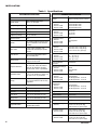
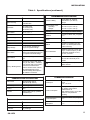
1
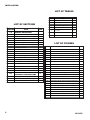
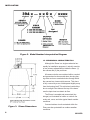
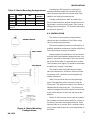
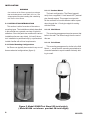
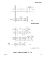
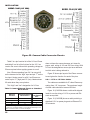
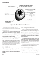
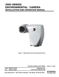
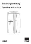
INSTALLATION
COHU, INC. ELECTRONICS DIVISION
Installation Manual
Figure 1. iDome
3940 Analog iDome and
3940 IP iDome
CAMERA/POSITIONER SYSTEM
July 17, 2006
Phone: 858-277-6700
[email protected]
www.cohu-cameras.com
FAX:
858-277-0221
Cohu Electronics • 3912 Calle Fortunada • San Diego, CA 92123-1827
6X-1070
1
INSTALLATION
LIST OF TABLES
TABLE
LIST OF SECTIONS
SECTION
2
TITLE
PAGE
TITLE
PAGE
1
Specifications
4
2
Basic Mounting Arrangements
7
3
Required Cable Characteristics
15
4
Type CA-252 Cable Connectors
19
5
Camera Ethernet Pinout vs. Standard
RJ-45 Pinout
22
6
24 V ac iDome Connector Functions
23
7
115 V ac iDome Connector Functions
23
1.0
GENERAL DESCRIPTION
3
1.1
Electrical Characteristics
3
1.2
Mechanical Characteristics
6
2.0
INSTALLATION
7
2.1
Installation Introduction
8
2.2
Equipment Supplied
12
2.3
Equipment Required But Not Supplied
14
2.4
Power Requirements
14
FIGURE
2.5
Pendant Mount Installation
16
1
iDome
1
2.6
Wall Mount Installation
16
2
Model Number Interpretation Diagram
6
2.7
Pole Mount Installation
17
3
iDome Dimensions
6
2.8
Alternate Mounting Methods
19
4
Basic Model Configurations
7
2.9
Cabling Requirements
19
5
Model 8540B Test Stand
8
2.10
Analog Output Video Capture
24
6
Typical Test Cables, 115 V ac
9
2.11
Viewer GUI
24
7
Typical RS-232 to RS-422 Converter
10
3.0
OPERATION
25
8
Quick Disconnect Assemby
11
4.0
MAINTENANCE
25
9
Wall Mount Arm
11
4.1
Firmware Uploads
25
10
Arm Dimensions
12
4.2
Preventive Maintenance
25
11
Typical Pole Mount
13
5.0
SHIPPING AND STATIC
DISCHARGE CONSIDERATIONS
26
12
iDome Quick Disconnect Mounting
14
13
Strap Wrench
14
LIST OF FIGURES
TITLE
PAGE
5.1
Unpacking & Receiving Inspection
26
14
Pole Mount Dimensions
15
5.2
Preparation for Shipment & Storage
26
15
Mast Arm Mount
15
5.3
Static Discharge Protection
27
16
Interconnection Diagram, iDome to Equipment Cabinet (typ)
17
17
Local Operation Test Setups
18
18
Type CA-252A Cable, Stripped Power & Ethernet Leads
20
19
Type CA-252B Cable, 115 V ac Plug & RJ-45 Etnernet Plug
20
20
Type CA-252P Cable, All Stripped Leads
21
21
Type CA-252Q Cable, Stripped RS-422 Leads
21
22
Camera Connector Pinout Diagram
22
23
iDome Maintenance Features
24
6X-1070
INSTALLATION
1.0 GENERAL DESCRIPTION
The 3940 iDome series is an integrated camera/
positioner unit that combines a high performance
digital signal processing camera, pan-and-tilt, and
control receiver for communications into one integrated package (figure 1). The 3940 is available in
two basic versions:
Analog Version: The Model 394x-x1xx has
NTSC video output and control functions are handled by RS-422. Firmware changes can be uploaded via an Ethernet connection
IP Version: The Model 394x-x9xx communicates via Ethernet and supplies video via Ethernet
IP video packets. On this IP version RS-422 is not
used. An IP dome is configured to connect to a hub.
Connecting it directly to a computer will require use
of a crossover cable or adapter.
Throughout this manual the entire assembly will
typically be referred to as the “iDome” or just the
“Dome.”
There will also be references to the “Analog”
version and the “IP” version when this distinction is
important.
Specifications are contained in table 1 and a
model number interpretation diagram is provided in
figure 2. This diagram can be used to interpret an
existing model number.
1.1 ELECTRICAL CHARACTERISTICS
The camera uses digital signal processing. It has
an internal source ID generator. Integration control
plus a built-in video storage card provides full color
continuous video even at very low light levels.
The iDome speeds are variable with maximums
of 250° per second for pan and tilt. Pan range is
a continuous 360 degrees while the tilt range is 0
to 90 degrees from the horizontal with auto-flip at
the 90° point. There are 64 preset positions with a
preset accuracy of 0.1 degree. When responding to
6X-1070
standard pan-preset or manual control, the iDome
can move with a pan speed of 250° per second.
This iDome will operate in temperature ranges
from -34° to +74° C and with winds of up to 90 mph.
The enclosure protects against salt, grime, dirt, and
moisture.
The integrated receiver/driver, contained within
the iDome, communicates using Cohu protocol
messages and will also control the digital DSP
camera functions. All iDome functions are operable
via either RS-422 or Ethernet serial communications
depending on the version.
In case of power failure, all 64 preset positions
are stored in nonvolatile memory.
Each iDome “address” within a surveillance system can be selected electronically from the Monitoring Center. There are no mechanical dip switches
to set at the camera, and each unit responds to the
central command only if addressed. This provides
greater integration flexibility for the designer and
more dynamic camera control for the operator.
Privacy zones can be set up using polygon
shaped windows drawn with the Viewer/Gui software. These blanking windows are generated electronically within the digital signal processing (DSP)
and provide positive control of such areas.
Electronic image stabalization (EIS) is available
for one version of the two 23X camera modules and
it is a standard feature for the 35X camera module.
This EIS feature helps to minimize the effects of
slight vibrations on a Dome in certain mounting situations — such as when it is mounted on a tall pole.
1.1.1 Control Software
The analog and the IP versions of this Dome
each require different software to control them and
to view their video. Separate manuals cover these
Viewers. Refer to Cohu manual part number 6X1071 for the IP viewer/GUI manual and part number
6X-1072 for the analog viewer/GUI manual.
3
INSTALLATION
Table 1. Specifications
SYSTEM SPECIFICATIONS
PAN/TILT DRIVE
Angular Travel
360° continuous pan range
-90° to +5° tilt range
Pan Speed (preset)
250°/second
Pan Speed (manual)
0.1° to >80°/sec
Tilt Speed (preset)
80°/sec
Tilt Speed (manual)
0.1° to >40°/sec
Preset Accuracy
>0.1°
Presets
64 preset positions (pan, tilt, zoom,
focus coordinates, & 24 character
ID label)
Video Tours
8 tours, each consisting of 32
presets with dwell time per preset
per tour
Sector Zones
Up to 16 programmable zones in
the horizontal plane
Privacy Zones
8 zones can be set by drawing
polygons on the scene
Compass Direction
8 or 16 direction points (i.e., north,
NE, east, SE, south, SW, west, &
NW) can be displayed. Function
can be on/off, 3 sec, or permanent.
Absolute Position
Displayed in 0 to 359° azimuth &
+14° to -95° elevation. Function can
be on/off, 3 sec, or permanent.
Cloning
Positioner settings (presets, title,
etc) can be saved to a file for easy
duplication
Imager
Resolution
23X lens:
23X lens & EIS:
35X lens & EIS:
1/4 inch interline transfer color CCD
NTSC for analog version of iDome
470 horizontal tv lines
470 horizontal tv lines
520 horizontal tv lines
Pixels
23X lens:
23X lens & EIS:
35X lens & EIS:
724 X 494
711 X 485
768 X 494
Progressive Scan
23X lens:
23X lens & EIS:
35X lens & EIS
Yes
Not Supported
Yes
Lens Zoom
23X lens:
23X lens & EIS:
35X lens & EIS
3.6 to 82.8 mm, f1.6 (w) f3.7(t)
3.6 to 82.8 mm, f1.6 (w) f3.7(t)
3.4 to 119 mm, f1.4 (w) f4.2(t)
Lens Hor. Angle of View
23X lens:
23X lens & EIS:
35X lens & EIS
Iris/Focus/Shutter
Operation
54° (w) 2.5° (t)
41.5° (w) 1.9° (t)
55.8° (w) 1.7° (t)
Auto/Manual
Wide Dynamic Range
23X lens:
23X lens & EIS:
35X lens & EIS
On/off
Not supported
On/off
EIS at 5 Hz Suppression
23X lens:
23X lens & EIS:
35X lens & EIS
Not Supported
20 dB suppression 7 to17 Hz
20 dB suppression 7 to17 Hz
Camera ID
2 lines of 24 characters
EIS at 16Hz
Suppression
23X lens:
23X lens & EIS:
35X lens & EIS
Preset ID
1 line of 24 characters
Digital Zoom
Auto/manual (12X)
Sector Zone
1 line of 24 characters per zone
White Balance
Auto/manual
Privacy Zone
1 line of 24 characters per zone
Sync
Crystal / phase adjust line lock
Alarm Label
2 lines of 24 characters
S/N
>50 dB
Compass/Position
1 line. Includes compass direction
and absolute position
Sensitivity (scene)
23X lens:
3 lux at 1/60 sec (color day)
0.2 lux at 1/4 sec (color day)
0.02 lux at 1/4 sec (mono night)
Sensitivity (scene)
23X lens & EIS:
2 lux at 1/60 sec (color day)
0.2 lux at 1/4 sec (color day)
0.01 lux at 1/4 sec (mono night)
Sensitivity (scene)
35X lens & EIS
1 lux at 1/60 sec (color day)
0.1 lux at 1/4 sec (color day)
0.01 lux at 1/4 sec (mono night)
TITLE GENERATION
4
CAMERA SPECIFICATIONS
Not Supported
20 dB suppression 3 to13 Hz
20 dB suppression 3 to13 Hz
6X-1070
INSTALLATION
Table 1. Specifications (continued)
VIDEO SPECIFICATIONS
VLIW/DSP
ENVIRONMENTAL SPECIFICATIONS
TI TMS320DM642-600
Video Encoding
MPEG4 ISO/IEC 14496-2 ASP;
RTP/UDP stack
640 x 480 (VGA)
640 X 240 (2 CIF)
320 X 240 (1 CIF)
Resolution
Frame Rates
30, 15, 8, 4, 2, 1
Bit Rates
64 k to 3 MB
Data Encoding
RTSP/TCP/IP stack
Image Memory
96 MB SDRAM
Network
100Base T fast Ethernet connection
Image Storage
1 to 30 minutes, depending on
image management settings
Video Motion
8 separate windows, 1200 ROI per
window, 255 sensitivity levels, fixed
or progressive threshold settings.
Logo Insertion
Supports bmp image insertion for
logo
Privacy / Masking Zones
Supports 64 polygon mask areas
(0.8° per side, with 0.1° resolution).
Each polygon mask can be turned
on/off at a user defined zoom
position. All video below & above
user-defined tilt angle can be
masked. Masking areas adjust in
size relative to zoom level.
Protection Rating
Ambient Temp. Limits
Operating:
Storage:
-34 to 50 °C (-27 to 122 °F)
-40 to 85 °C (-40 to 185 °F)
Humidity
Up to 100 percent relative humidity
Vibration
Conforms to NEMA TS2, paragraph
2.1.9
Shock
Conforms to NEMA TS2 paragraph
2.1.10
Altitude
Sea level to equivalent of 3,000
meters / 10, 000 feet (508 mm/20
inches of mercury)
Air Contaminants
Withstands exposure to sand, dust,
fungus, & salt atmosphere, per MILSTD-5400T, paragraph 3.2.24.7,
3.2.24.8, & 3.2.24.9
Acoustics
Can withstand environments greater
than 150 dB continuously for 30
minutes
EMI
FCC rules, part 15, subpart J, for
class B devices
POWERS SPECIFICATIONS
COMMUNICATIONS SPECIFICATIONS
Data Format
RS-422 (analog version)
IEEE 802.3U (IP version)
PTZ Latency
<200 ms (typical)
Protocol
Cohu
Firmware
Stored in flash memory, uploaded
via Ethernet port
MECHANICAL SPECIFICATIONS
Weight
14 lb
Dimensions
See figure 3
Connector
18 pin MS type
6X-1070
IP67 & NEMA 4X; sealed &
pressurized to 5 psi with dry
nitrogen
Power Input
120 V ac (89 V ac to 135 V ac),
60 Hz
or 24 V ac 60 Hz
Power Consumption
Basic power consumption is 37 W.
P/T stepper motors add 23.
Heaters add 54 W.
Total maximum draw is 114 W with
heaters on and pan/tilt both
operating.
Power Interruption
Conforms to NEMA TS2 paragraph
2.1.4
Power Transients/
Interruptions
Conforms to NEMA TS2 paragraph
2.1.6
5
INSTALLATION
Figure 2. Model Number Interpretation Diagram
1.2 MECHANICAL CHARACTERISTICS
Although the iDome is a single mechanical assembly for installation purposes, it actually consists
of two primary subassemblies inside the dome: (1)
the camera and (2) the positioner.
All camera circuits are contained within a sealed
and pressurized environmental dome housing having either a clear or smoked window through which
the camera lens views outside scenes. This dome
is fully covered by a sun shield spaced slightly away
from the housing itself. This minimizes heat buildup
due to sunlight. Vent holes at the top of the dome
must be kept clear to maintain air flow.
The iDome is a sealed and pressurized (dry
nitrogen) unit intended for indoor or outdoor use
under rain, snow, and other typical harsh weather
conditions.
Figure 3. i Dome Dimensions
6
Communications circuits contained within the
iDome are also protected from outdoor weather
conditions.
6X-1070
INSTALLATION
Table 2. Basic Mounting Arrangements
MOUNT
CONFIG.
Pendant
Wall
Pole
NOTE: Dot ( •
configuration.
iDOME
ARM
•
•
•
•
•
POLE
BRACKET
•
) designates items supplied for each mounting
A sealing type MS connector is used on the
housing and when mated with a similar MS type
cable connector a good environmental seal is provided for the mating pins and sockets.
A single multiconductor cable is routed to the
iDome location and then passed through the mounting pendant to provide for all signal, video, and operating power connections. Pin functions and layout
are shown in figure 22.
2.0 INSTALLATION
This section of the manual provides general
instructions about installation of the iDome using
various mounting arrangements.
The actual installation should be performed by a
qualified installation professional familiar with all the
local requirements for proper installation.
Always preplan the installation to be sure that all
required cabling and address assignments are completed. It may also be important to know the orientation of the iDome when it is mounted at its location.
The Schrader valve (figure 23) should be accessible
for adding dry nitrogen if necessary.
The model number label indicated a mechanical home reference for all iDomes. Electrical home
for panning is 90° clockwise from this position as
viewed from above.
Table 2 lists the three basic mounting arrangements. That pendant version consists of only the
iDome itself. The wall mount version of an iDome is
shipped with the wall mount arm. The pole mount
version is shipped with both the wall mount arm and
a pole mount bracket to which the wall mount arm
attaches.
Figure 4. Basic Mounting
Configurations
6X-1070
Section 5 of this manual covers receiving inspection, packing and return requirements for a return to
the factory, and static discharge protections. Static
should mainly be of concern when working inside a
unit, and this manual does not cover disassembly of
the Dome.
7
INSTALLATION
WARNING
One versions of the iDome operate from voltages
that can be dangerous: model 3945 (115 V ac). Use
all appropriate care when installing and maintaining
this version of the iDome.
2.1 INSTALLATION INTRODUCTION
This section is a brief overview of the various
mounting types. The installation methods described
in this manual are a general overview of typical installations. Since the particular conditions at various
installation sites can vary widely, it is best if the actual installation is performed only by a professional
installer familiar with all local requirements.
2.1.1 Basic Mounting Configurations
An iDome can typically be mounted in any one of
three mechanical configurations (figure 4):
2.1.1.1 Pendant Mount
The basic configuration. The iDome hangs directly from a supplied 1.5-inch female NPT (national
pipe thread) support. This support must provide
for the connector of a multiconductor cable to pass
down through the 1.5-inch pipe nipple for mating
with the iDome.
2.1.1.2. Wall Mount
This mounting arrangement requires an arm that
bolts to the wall. The iDome hangs from the end of
this arm.
2.1.1.3. Pole Mount
This mounting arrangement is similar to the Wall
Mount — except that the mounting arm attaches to
a bracket fastened to a pole instead of directly bolting to a wall.
Figure 5. Model 8540B Test Stand (23-inch height).
( Model 8540A -not shown- provides 38-inch height)
8
6X-1070
INSTALLATION
IP Video Models
Firmware
Upload
Only
Analog Video Models
Figure 6. Typical Test Cables, 115 V ac
6X-1070
9
INSTALLATION
This converter changes the RS-232 output of a PC to RS-422 for
communications with an iDome during field setup and testing.
A local PC with Win MPC software typically is used in this application.
If this converer is plugged into the RS-232 output from an F/0
converter, 12 V dc operating power will likely have to be applied
to the 12 V dc terminal lugs. These F/O to RS-232 converters
typically do not have sufficient current on the handshake lines
to power the 232/422 converter. This application of the 232/422
converter would typically occur as part of a fixed installation inside an equipment cabinet located near an iDome. The 232/422
converter would be part of a type CA-295G cable.
Figure 7. RS-232 to RS-422 Converter
Table 2 summarizes the major items supplied for
each of these three installation methods. Each of
these installations will be expanded upon in a later
sections.
2.1.2 Installation Checklist
Before starting the installation of an iDome the following check lists should be read for an overview of
the process.
2.1.2.1 Analog Test Bench Checkout - To
check out an iDome and set its address at a test
bench before taking it into the field for installation,
use the following as a guideline:
1. Mount the iDome to a test stand (figure 5).
This stand is also available with another
set of three legs that increases it from a
20-inch height to a 38 inch height.
2. Connect a test cable (figure 6) to the connector
at the top of the dome
3. Connect the other end of the cable to the laptop. (An RS-232 to RS-422 converter will likely
be required. See figure 7. If the PC does not
have an RS-232 port it will then be necessary
to use a USB to RS-232 converter. See section 2.10 for mention of a suitable USB/232
converter.)
10
CAUTION
Step 4 assumes that the iDome operates from
115 V ac power. This cable cannot be used with
an iDome operating from 24 V ac. Different connector pins are used.
4. Connect the power plug of this cable to 115
V ac — (This cable cannot be used with
24 V ac iDomes.)
6. Install the iDome Analog Viewer software
on the laptop.
7. Establish the required communications
parameters
8. Set (or verify) the iDome address (When
installed in the system, each item of equipment must have a unique address). Place
this address on the iDome with a removable
piece of masking tape.
9. Verify proper operation of all the various
functions controllable through the iDome
menus.
10. Release the iDome for field installation
after it has been determined all functions
are working.
2.1.2.2 IP Dome Test Bench Checkout
Checking out an IP version of the Dome requires a PC running the required software. This
6X-1070
INSTALLATION
figure 17.
2.1.2.3. Field Installation Procedure -
Use the following outline to become
familiar with the steps required to install an
iDome at its field location:
1. Route the cable to the mounting
location of the iDome.
2. Route the cable through any mounting
arms or brackets.
3. Remove the safety strap from the
iDome quick disconnect fastener
4. Thread the nipple portion of the quick
disconnect into the mounting bracket or
arm.
Figure 8. Quick Disconnect Assembly
includes both the Cohu Ateme and Cohu Viewer
software.
Connecting a PC directly to an IP iDome requires
an Ethernet crossover cable or adapter. When using one of the Cohu supplied cables that already
has a RJ-45 plug, an adapter will have to be used
so that another cable can make the connection to
the PC. In this case, either a crossover adapter
or a crossover cable can be used for the extension to the PC. But both should not be of the
crossover type. See interconnection diagram A in
5. Route the cable down through this nipple
and attach it to the iDome connector
6. Wrap the connector with self sealing
waterproofing tape to ensure a long-term
trouble free installation.
7. Attach the dome half of the quick discon-
Figure 9. Wall Mount Arm
6X-1070
11
INSTALLATION
Figure 10. Arm Dimensions
nect to the half mounted to the arm or other
bracket. (If a particular orientation is required
be sure to mount it correctly positioned.)
8. Attach the safety strap back to the other half
of the quick disconnect.
9. Connect the laptop to the iDome at the junction box or equipment cabinet.
10. Verity (or set) the address and check all
operations.
11. Release the iDome for service.
2.2 EQUIPMENT SUPPLIED
Depending on the mounting configuration, several variations of equipment can be supplied. Refer
to table 2 for a list of the basic differences between
models as they relate to mounting arrangements. A
mating connector is supplied with each camera.
12
2.2.1 PEDD (Pendant Mount). See figure 8.
Pendant mounting is the most basic of the three
mounting arrangements. The top half of a quick-disconnect assembly is threaded into a site supplied
1.5-inch NPT mount.
2.2.2 WALL (Wall Mount). See figure 9.
With a wall mount the iDome hangs from the
end of an arm which is attached to a wall. Figure
9 gives dimensions of the arm and adapter plate.
This wall must not only have four mounting bolts but
also a hole centered between these bolts through
which the cable must pass. A weather-tight gasket
should be used between the arm and wall.
2.2.3 POLE (Pole Mount). See figure 11.
Mounting to a pole is similar to mounting to a
6X-1070
INSTALLATION
wall. For mounting to a pole, the four mounting bolts
are provided by a bracket. This bracket is attached
to the pole by stainless steel straps. This strapping
requires a special tensioning tool.
Cable routing when using a pole mount depends
upon the situation encountered. It can either be
directed down behind the pole bracket or, if arrangements have been made for this, into the pole. Junction boxes, drip loops, and weather proof integrity
of the connectors must be considered before starting the installation.
It is recommended that the iDome connector and
the cable connector attached to it be wrapped with a
self sealing weatherproof tape such as Coax Seal:
www.coaxseal.com
The web site for Coax Seal has complete information about this product.
2.3 EQUIPMENT REQUIRED BUT NOT
SUPPLIED
Each installation will have unique requirements
for necessary cables, equipment, and miscellaneous accessory items. This following is a list of the
most basic items required for installing at the site
location of the iDome. Some of these items can be
ordered with the iDome and thus would be provided
in those cases.
Figure 11. Typical Pole Mount
6X-1070
13
INSTALLATION
ing hardware
• Cable, multiconductor,
iDome to equipment cabinet
• Connector sealing tape
such as Coax Seal
• Junction box or equipment
cabinet for system connections
• Power source
• Viewer software
• Fiber optic or other type
system interconnection
• Cables, at system interconnect cabinet
2.4 POWER REQUIREMENTS
There are two versions of
the iDome related to power:
• 5/16-inch grade 316 stainless steel mount-
Figure 12. iDome Quick Disconnect Mounting
• 24 V ac (Model 3944-xxxx /
xxxx)
• 115 V ac (Model 3945-xxxx /
xxxx)
The model number label is attached to the bottom of an iDome. (Electrical home for camera pan is
90° clockwise from this label viewed from above.)
Basic power consumption is 37 watts. When
both stepper motors are active, power consumption
becomes 60 watts. When the thermostat applies
power to the heaters, an additional 54 watts is consumed. Thus the maximum power draw with stepper
motors both running and the heaters drawing power
is 114 watts.
Figure 13. Strap Wrench
14
The iDome heaters draw 54 watts during cold
conditions when the thermostat has them turned
on. Otherwise power consumption is 37 watts with
6X-1070
INSTALLATION
the stepper motors idle or 60 watts when they are
active. Thus the maximum power draw at any one
time is 114 watts with the heaters on and pan/tilt in
operation.
All electrical connections to and from the iDome
are made through a single cable entering at the top.
A second version of the Camera is wired for 24 V
ac. Pins “B” (high) and “T” (low) are used to provide
24 V ac Camera operating power. If heaters are
installed, a separate 24 V ac is applied to pins C
(high) and K (low). This input will require that a minimum of 2.7 amps be available (65 watts).
Ac ground for both heater power and camera
power of the 24 V ac inputs is pin “G.”
Table 3 lists basic characteristics that are required for a typical multiconductor cable interconnected with the iDome.
Figure 14. Pole Mount Dimensions
Table 3. Required Cable Characteristics
CONDUCTOR
FUNCTION
TYPICAL CHARACTERISTICS
VIDEO
RG-59/U (75 ohm), 100 % copper conductor,
95% minimum braided shield
RS-422 DATA
2 pair, twisted with overall shield, and a data
ground wire required. All 26 AWG minimum
Ethernet
2 pairs twisted with overall shield, 26 AWG
minimum (CAT5 cable or better)
POWER
It should be noted that RG-59 coaxial cable is
available in many different versions with a great variety of characteristics, and many are not suitable for
use with video. Always be sure to use RG-59/U with
100 percent copper conductors and at least 95%
braid coverage.
The data conductors should be at least 26
gauge twisted pairs. With these data conductors it
is desired to minimize capacitance loading and thus
3-conductor, 22 AWG minimum
Wire gauges depend on length of the cable run. This table
assumes a 115 V ac iDome and 250 foot cable run. The RS422 cable length is limited by signal deterioration
considerations to about 1000 feet. The Ethernet CAT5 cable
is limited to 328 feet due to packet collision considerations.
Use high quality cable suitable for the intended location.
Figure 15 Mast Arm Mount
6X-1070
15
INSTALLATION
only an overall shield should be used — not individual shields over the twisted pairs.
The power conductors should be as heavy a
gauge as possible. Cohu cables use 22 gauge conductors for power. When high quality coaxial cable
is being used, these power conductors can become
the limiting factor for long cable runs.
This problem is especially acute with the 24 V
ac version of the iDome since it draws much more
current than the 115 V ac version. Thus they typically have shorter allowable cable runs unless the
power wiring is increased to a much larger size. To
minimize this problem, operating power and heater
power are supplied on separate inputs for a 24 V ac
iDome.
When the heaters turn on under thermostatic
control during low ambient temperatures the voltage
drops at the iDome due to resistance in the wires.
With the 24 V ac version this does not decrease
operating power since it is on a separate input, but
for the 115 V ac version, operating voltage cannot
be allowed to drop below the requirements of the
iDome when heaters are energized by the thermostat.
Power wiring of greater sizes reduces this voltage drop when heaters cycle on and off. When
designing a custom installation it is best to perform
a few Ohm’s Law calculations to determine what is
the minimum allowable size for power wiring.
2.5 PENDENT MOUNT INSTALLATION
An iDome in the pendent configuration is its
most basic form. No mounting arms or adapters are
provided. The 1.5 inch NPT pipe thread on top the
dome is attached to an appropriate mount supplied
by the installer. Provisions must be made for the
cable to pass through this mount down through the
quick disconnect mount (figure 12) and onto the
connector on top the iDome.
16
2.6 WALL MOUNT INSTALLATION
With a wall-mount installation, a support arm
bolts to a wall and the iDome then hangs from the
end of that arm.
1. Remove the safety strap from the top half
of the quick disconnect (the half with the
threaded nipple attached).
2. Thread the quick disconnect nipple into the
mounting arm and tighten with a strap wrench
(figure 13).
3. Verify that the system cable is accessible for
connection to the iDome connector at the end
of the arm. This cable typically must pass
through the wall and into the arm.
4. Route the system cable out of the wall and
into the back of the wall mount arm. Continue
the cable through the arm and out the hole
at the iDome mounting location.
5. Install a weather tight gasket between the
arm and the surface of the wall.
6. Bolt the Arm to the wall.
7. Attach the cable plug to the iDome connector.
9. Orient the iDome properly and attach it to the
other half of the quick disconnect mounted
to the arm.
10. Reattach the safety strap.
11. Proceed to section 2.10.5, the checkout
procedure.
2.7 POLE MOUNT INSTALLATION
A pole mount installation is similar to the wall
mount installation except that the arm fastens to a
bracket (figure 14) attached to the pole instead of
directly to a wall.
6X-1070
INSTALLATION
Figure 16. Interconnection Diagram, iDome to Equipment Cabinet (typical)
1. Remove the safety strap from the top half
of the quick disconnect (the half with the
threaded nipple attached).
2. Thread the quick disconnect nipple into the
mounting arm and tighten with a strap wrench
(figure 13).
ing and out the hole at the iDome quick
disconnect.
5. Provide for weather tight mounting at the
pole mount bracket.
6. Bolt the Arm to the bracket.
3. Verify that the system cable is accessible for
connection to the iDome connector at the end
of the arm. This cable typically must pass into
the back of the pole mount and then into the
arm - although various other cable routing
configurations are possible.
7. Attach the cable plug to the iDome connector.
4. Route the system cable through the mount-
10. Reattach the safety strap.
9. Orient the iDome properly and attach it to the
other half of the quick disconnect mounted
to the arm.
11. Proceed to section 2.10.5, the checkout
procedure.
6X-1070
17
INSTALLATION
Figure 17. Local Operation Test Setups
18
6X-1070
INSTALLATION
Table 4. Cable CA-252 Connectors
CABLE
VIDEO
MAIN
IP VIDEO
TYPE CONNECTOR CONNECTION
CA-252A
IP
CA-252B
IP
CA-252P
Analog
CA-252Q Analog
Note
Note
Note
Note
ANALOG
VIDEO
CONNECTION
RS-422 DATA
CONNECTION
POWER
CONNECTION
Cohu Type
1310230-011
stripped leads
n/a
n/a
stripped leads
RJ-45
n/a
n/a
115 V ac Plug
Note 1
and
Note 2
stripped leads
stripped leads
stripped leads
stripped leads
RJ-45 Note 3
BNC PLUG
stripped leads
115 V ac Plug
1. Equivalent types: MS3116F-14-18S and Amphenol/Bendix PT06E-14-18S(SR)
2. Main Connector mates with connector on permanently attached camera cable.
3. Data uploading only. No IP video out.
4. Maximum lenght of this cable is 250 feet.
2.8 ALTERNATE MOUNTING METHODS
Other mounting configurations are possible.
For example, figure 15 shows a mount suitable for
attaching to an arm suspended over a roadway or
other location. This mount straps to the arm and is
threaded for 1.5 inch NPT mounting. Installing this
arm mount requires the use of a strap tensioning
tool.
2.9 CABLING REQUIREMENTS
Table 4 lists typical cables available for use with
the iDome. This table summarizes the characteristics of each cable. “Prepped” in the table indicates
that the wire leads are stripped and pre tinned with
solder for attachment to a terminal strip or similar
device.
Note that these cables are listed for use with 115
V ac iDomes only. Cables for the 24 V ac versions
of an iDome are special order.
Assembly/wiring diagrams for the cables are
shown in figure 18 through figure 21.
A cable connected to the iDome usually routes
to equipment in a nearby junction box or equipment
cabinet from where another cable continues back to
the system control station. Fiber optic cable is often
used for this link back to a central location.
Pre-plan all system cabling for an installation.
Before an iDome is bolted in place, the cable from
the junction box or cabinet must be available to attach to the iDome at its mounting location.
If an IP video version of a 115 V ac iDome is to
be installed then either cable CA-252A or CA-252B
can be used.These are shown in figures 18 and 19.
If an analog video version of a 115 V ac iDome is
to be operated via its RS-422 pins on the connector
then either cable CA-252P or CA-252Q must be
used.These are shown in figures 20 and 21.
Cables for 24 V ac operation are currently special order and do not appear in this manual. The
pinput configuration for 24 V ac, though, is shown
in figure 22.
Table 3 lists some basic characteristics required
for the conductors in a typical cable. Two considerations related to the cables are degredation of
signal quality due to cable effects and interferrence
signals and loss of voltage on power wiring. It is
important that high quality copper conductor 75 ohm
coaxial cable be used.
Text continued on page 22
6X-1070
19
INSTALLATION
CA252A
IP Video Out Cable
Figure 18. Type CA-252A Cable, Stripped Power & Ethernet Leads
CA252B
IP Video Out Cable
Figure 19. Type CA-252B Cable, 115 V ac Plug & RJ-45 Ethernet Plug
20
6X-1070
INSTALLATION
CA252P
Analog Video Out Cable
Figure 20. Type CA-252P Cable,
All Stripped Leads
CA252Q
Analog Video Out Cable
Figure 21. Type CA-252Q Cable,
Stripped RS-422 Leads
6X-1070
21
INSTALLATION
Figure 22. Camera Cable Connector Pinouts
Table 5 is a pin function list of the 24 V ac iDome
and table 6 is a list of pin fuctions for the 115 V ac
version. Be sure to know which operating voltage an
iDome requires before applying power to a unit.
Also, iDomes operating from 24 V ac use pin B
as the camera circuits “high” input and pin “T” as the
low input. Heater power for a 24 V ac iDome connects to pins “C” (high) and “K” (low). Heaters draw
65 watts when they are cycled on.
This “high” and “low” designation for 24 V ac
Table 5. Camera Ethernet Pinout vs. Standard
RJ-45 Pinout
Ethernet
Function
Corresponding
Camera Connector
RJ-45 Ethernet
Ethernet Pins
Pins
Tx+
D
1
Tx-
E
2
Rx+
F
3
Rx-
H
6
does not have the same relevance as it does for
proper, safe wiring of 115 and 230 V ac wiring. With
24 V ac the designations serves just as a reference
to which wire is being referred to.
Figure 22 shows pin layout of the iDome connector and gives the function for each of the pins.
2.9.1 115 V ac IP Video Cables
Two cables are available for IP video iDomes operating from 115 V ac power. The maximum length
of either cable should not exceed 250 feet.
Figure 18 (CA-252A shows a cable with stripped
leads for on-site wiring of 115 V ac power and Ethernet as requiried.
Figure 19 (CA-252B) shows a cable providing a
standard 115 V ac power plug and an Ethernet RJ45 connector.
This Ethernet wiring is intended to connect directly to a hub, switch,
or router. For connection directly to a PC it will be necessary to use
either a crossover cable or a crossover adapter.
22
6X-1070
INSTALLATION
Table 6. 24 V ac iDome Connector Functions
Table 7. 115 V ac iDome Connector Functions
PIN
FUNCTION
PIN
FUNCTION
A
Video Shield (75 ohm )
A
Video Shield (75 ohm )
B
24 V ac high (camera)
B
no connection
C
24 V ac high (heaters)
C
no connection
D
Ethermet Tx+
D
Ethernet Tx+
E
Ethermet Tx-
E
Ethernet Tx-
F
Ethermet Rx+
F
Ethernet Rx+
G
24 V ac Ground
G
115 V ac Ground
H
Ethermet Rx-
H
Ethernet Rx-
J
no connection
J
no connection
K
24 V ac low (heaters)
K
no connection
L
Video Out (75 ohm)
L
Video Out (75 ohm)
M
RS-422 Command In + (Rx+)
M
RS-422 Command In + (Rx+)
N
RS-422 Command In - (Rx-)
N
RS-422 Command In - (Rx-)
P
RS-422 Data Ground
P
RS-422 Data Ground
R
RS-422 Response Out - (Tx-)
R
RS-422 Response Out - (Tx-)
S
RS-422 Response Out + (Tx+)
S
RS-422 Response Out + (Tx+)
T
24 V ac neutral (low)
T
115 V ac neutral (low)
U
no connection
U
115 V ac line (hot/high)
The Ethernet connections on this iDome are intended to
connect to a hub , switch. or router if it is to be connected
directly to a PC a crossover cable or adapter will have to
be used.
The Ethernet connections on this iDome are intended to
connect to a hub , switch. or router if it is to be connected
directly to a PC a crossover cable or adapter will have to
be used.
2.9.2 115 V ac Analog Video Cables
uploading.
Two cables are available for analog video
iDomes operating from 115 V ac power. These
cables require RS-422 connections for control of
camera and pan/tilt functions. The maximum length
for either of these cables should not exceed 250
feet.
Figure 21 (CA-252Q) has a BNC plug for video
output, an ac plug for the 115 V ac input, stripped
and tinned leads for the RS-422 communications,
and an RJ-45 connector for the Ethernet up-loadoing of firmware uploading.
Figure 20 (CA-252P) has stripped and tinned
leads for analog video output, 115 V ac power input,
control data communications, and Ethernet firmware
6X-1070
2.10 Analog Output Video Capture
When setting up an analog output iDome (Model
394x-x10x/xxxx), a video capture module must be
used.
23
INSTALLATION
Figure 23. iDome Maintenance Features
This module converts the NTSC video to a
compressed digital form that viewer software on the
computer can use.
See figure 17 for a typical test setup showing an
analog iDome interconnected to a laptop computer.
This setup also makes use of an RS-232 to RS-422
converter so that the serial port of the laptop can
communitate with the RS-422 iDome.
2.11.1 Analog Version Viewer/GUI
Figure 17 shows interconnections for using the
analog viewer/GUI. This version of the viewer is intended for setting up and testing the analog iDome.
This viewer is not the software for day-to-day operations using the camera in a system. It is capable of
controlling and viewing only one iDome to which it is
directly connected.
If the laptop does not have an RS-232 port it will
be necessary to substitute a USB to RS-232 converter. Not all models of these converters will work.
One source for a converter that should work is the
IO Gear Model GUC232A (www.iogear.com). This
site has a listing of many local and online retailers
where this converter can be purchased.
The viewer requires a video capture card so that
scene video from the camera module can be viewed
on the laptop screen. The Viewer only recognizes a
frame grabber; an analog monitor cannot be substituted for this test setup.
2.11 VIEWER GUI
2.11.2 IP Version Viewer/GUI
The analog version of the iDome and the IP
version each require different Viewer / Control
software. And the IP version also requires decoder
software.
Installation of the IP Viewer GUI and use of of its
functions are included in a separate manual. Refer
to the iPi Viewer manual (part number 6X-1071).
24
This Viewer/GUI for the analog iDome is covered
in a separate manual (part number 6X-1072).
Decoder software also must be operating on
6X-1070
INSTALLATION
any PC connected to the IP version of the iDome.
Decoder software decompresses the MPEG video
arriving from the iDome and converts it to a form usable by the Viewer software.
3.0 OPERATION
All functions of the analog and the IP versions of
this Dome are controlled by their respective viewer/
GUI softwares. Refer to the manuals for those software packages for installation, setup, and operation
insturctions.
4.0 MAINTENANCE
This maintenance section consists of three parts:
firmware uploading, troubleshooting, and preventive maintenance.
Figure 23 is a top view of the iDome showing
various items related to maintenance operations.
For this illustration the 1.5-inch NPT nipple has
been removed so that the 18-pin connector can be
seen.
The quick-disconnect assembly an be rotated 1/4
turn to separate the two halves. Note that a safety
strap connects the two halves so that the dome cannot accidentally fall. When installing the top (nipple)
half of this assembly the safety strap is temporarily
removed so that it can be threaded into the female
threads of the supporting device. Always be sure to
immediately reattach this strap after the dome half
of the assembly is attached. Also snug down the
locking bolt that secures the two halves of the assembly from turning.
4.1 Firmware Uploads
Uploading firmware upgrades into an analog version of the iDome requires use of the Ethernet connections. That is the only function for the Ethernet
connection on an Analog camera.
Uploading firmware upgrades into the IP version
6X-1070
of the iDome also uses the Ethernet interface since
this is the only method of exchanging data communications and receiving video from an IP version of
the iDome.
Uploading to either veresion of the camera requires not only having a file with the proper firmware
and but also the uploading software for communications with the iDome.
4.2 Preventive Maintenance
The iDome System contains no user serviceable
components. If there is a problem with your system,
it must be returned to Cohu for authorized servicing.
As well, there are some periodic maintenance
routines that may be necessary, in order to provide
optimum operation and product performance. These
procedures will generally only need to be performed
on an as needed basis. However, it is recommended that a regular checkup (once every year or
two) be performed to insure the following items are
maintained.
1. Acrylic Window: The iDome acrylic window
may need to be cleaned of any grime that
may accumulate over time, as would be expected of an outdoor device. If the picture
quality of the iDome becomes affected by
excessive grime on the acrylic window, clean
with a mild, nonabrasive detergent and water
with a soft cloth.
2. Dry Nitrogen Pressure: The iDome is a sealed
and pressurized device that over time, may
need to be repressurized with dry nitrogen.
Low pressure can be suspected when the
iDome low pressure message is displayed on
the video signal (assuming the iDome alarm
message is set to be enabled), and when
internal moisture condensation is noticed on
the interior of the iDome units acrylic window.
If either one of these conditions is present,
Cohu offers a lifetime “pressurization” warranty (Refer to Cohu’s Warranty Statement).
You may elect to send the unit into Cohu for
25
INSTALLATION
repressurization of the dry nitrogen or elect
to do so yourself. The iDome uses a standard
Schrader valve to repressurize. Use only dry
nitrogen for this purpose. Pressurize to 5 psig.
A pressure relief valve releases pressure at
5 psig.
3. A visual check of the iDome units outer
sunshield to insure the vent holes are not
obstructed from allowing free air passage.
5.0
SHIPPING AND STATIC DISCHARGE
CONSIDERATIONS
This section covers both receiving inspection and
shipping the Camera back to the factory. if necessary.
ing materials. Since shipping damage is the carrier’s responsibility, the carrier will furnish you with an
inspection report and the necessary forms for filing
the concealed-damage claim
5.2 PREPARATION FOR SHIPMENT AND
STORAGE
For storage periods exceeding about one month,
seal the unit in a vapor-proof bag containing a fresh
desiccant pack.
Maintain the iDome storage environment within a
range of -30 to 70 °C (-22 to 158 °F).
When working with an iDome that has been
opened it is particularly necessary to observe all
standard practices to avoid static discharge. Section
5.3 covers some of these practices.
For shipment, package with enough foam padding or other packing material to prevent damage
that can occur during shipping. The original shipping carton is a good container if it has not been
damaged or subjected to excessive moisture. For
shipping to the factory by Common Carrier, use the
following address:
5.1 UNPACKING AND RECEIVING INSPECTION
Cohu Electronics
3912 Calle Fortunada
San Diego, CA 92123-1827
This iDome was thoroughly tested and carefully
packed in the factory. Upon acceptance by the carrier, they assume responsibility for its safe arrival.
Should you receive this item in a damaged condition, apparent or concealed, a claim for damage
must be made to the carrier. To return an iDome
or related product to the factory for service, please
contact the Customer Service Department for a
Return Authorization Number.“ If a visual inspection
shows damage upon receipt of this shipment, it must
be noted on the freight bill or express receipt and
the notation signed by the carrier’s agent. Failure
to do this can result in the carrier refusing to honor
the claim.“ When the damage is not apparent until
the unit is unpacked, a claim for concealed damage
must be made. Make a mail or phone request to the
carrier for inspection immediately upon discovery of
the concealed damage. Keep all cartons and pack26
Please contact the Customer Service Department for a Return Authorization (RA) number before
sending any shipments to the factory:
[email protected]
or
858-277-6700 extension 261
Prominently display the RA number on the outside of the shipping container(s) and on paperwork
contained inside. Give a brief description of why the
equipment is being returned and list the symptoms
of any problems being experienced with the equipment.
5.3 STATIC DISCHARGE PROTECTION
Procedures in this manual do not require entry
into the housing of the iDome. However in the event
that an open unit were available, the following precautions should be followed:
6X-1070
INSTALLATION
CAUTION
This iDome contains sensitive devices that can
be damaged by static discharge. Use appropriate
static control methods when working inside the
iDome.
Components used in modern electronic equipment, especially solid state devices, are susceptible
to damage from static discharge. The relative susceptibility to damage for semiconductors varies from
low with TTL to high with CMOS. Most other semiconductors fall between TTL and CMOS in susceptibility to static discharge. As a minimum, therefore,
observe the following practices when working inside
this or any other electronic equipment:
devices at the work bench are properly installed and
maintained.“ Standard grounding mats and wrist
straps purchased for use at work benches are supplied with leads having current limiting resistors for
safety. Never substitute with a grounding lead not
having the resistor.
-end text-
1. Use conductive sheet stock on the work
bench surface.
2. Connect the sheet stock to ground through
an 1 megohm or greater value resistor.
3. Use a wrist strap connected to ground through
an 1 megohm or greater value resistor when
working at the bench.
4. Maintain relative humidity of the room above
30 percent. This may require a room humidifier. Working on circuits with relative humidity below 30 percent requires extraordinary
procedures not listed here.
5. Use antistatic bags to store and transport
an exposes chassis, circuit boards, and
components. Use new antistatic bags. Old,
used bags loose their static protection properties.
This list serves as a reminder of the minimum acceptable practices. Be sure that all static discharge
6X-1070
27
INSTALLATION
COHU ELECTRONICS WARRANTY
Cohu, Inc., Electronics Division warrants equipment manufactured to be free from defects of material and
workmanship. Any part or parts will be repaired or replaced when proven by Cohu examination to have been defective
within two years from date of shipment to the original purchaser for standard CCD cameras and one year from date of
shipment to the original purchaser for intensified CCD cameras and all other Cohu manufactured products.
Pressurized Housings: Pressurized camera products include a lifetime pressurization warranty. Cohu will re-pressurize
at no charge returned environmental cameras not exhibiting evidence of physical damage due to misuse. All warranty
repairs will be performed at the factory or as otherwise authorized by Cohu in writing. Transportation charges to Cohu
shall be prepaid by purchaser.
Extended IR Cameras: Cameras utilizing extended infrared (extended IR) sensors found to exceed acceptable white
blemish specifications within one month of delivery shall be repaired without charge.
This warranty does not extend to Cohu equipment subjected to misuse, accident, neglect, improper application, or
repaired or altered by other than Cohu or those authorized by Cohu in writing. Cameras utilizing extended IR sensors are
not warranted for use in areas of elevated levels of cosmic radiation. Television image pickup tubes, image intensifiers,
lenses, and products manufactured by companies other than Cohu are warranted by the original manufacturer.
This warranty is in lieu of all other warranties, express, implied, or statutory, including warranties of fitness for a
particular purpose and merchantability, and sets forth buyers sole remedy in connection with such warranties. Cohu, in
no event, whether as a result of breach of contract or warranty, tort (including negligence) or otherwise, shall be liable
for any penalties regardless of reason; collateral, consequential, incidental, or exemplary damages, including without
limitation, any loss of profit or revenues, loss of use of any equipment or goods, or removal or re-installation of equipment
without prior written approval.
A Return Authorization (RA) Number must be obtained from Cohu prior to returning any item for warranty repair or
replacement.
4/03 man.
28
6X-1070