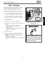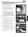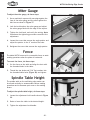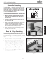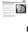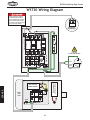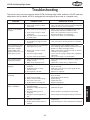
1
MODEL W1730 Oscillating Edge Sander 247569 INSTRUCTION MANUAL (FOR MODELS MANUFACTURED SINCE 10/11) Phone: 1-360-734-3482 • On-Line Technical Support: [email protected] COPYRIGHT © SEPTEMBER, 2004 BY WOODSTOCK INTERNATIONAL, INC., REVISED NOVEMBER, 2011 (TS) #6571CA WARNING: NO PORTION OF THIS MANUAL MAY BE REPRODUCED IN ANY SHAPE OR FORM WITHOUT THE WRITTEN APPROVAL OF WOODSTOCK INTERNATIONAL, INC. Printed in Taiwan This manual provides critical safety instructions on the proper setup, operation, maintenance, and service of this machine/tool. Save this document, refer to it often, and use it to instruct other operators. Failure to read, understand and follow the instructions in this manual may result in fire or serious personal injury—including amputation, electrocution, or death. The owner of this machine/tool is solely responsible for its safe use. This responsibility includes but is not limited to proper installation in a safe environment, personnel training and usage authorization, proper inspection and maintenance, manual availability and comprehension, application of safety devices, cutting/sanding/grinding tool integrity, and the usage of personal protective equipment. The manufacturer will not be held liable for injury or property damage from negligence, improper training, machine modifications or misuse. Some dust created by power sanding, sawing, grinding, drilling, and other construction activities contains chemicals known to the State of California to cause cancer, birth defects or other reproductive harm. Some examples of these chemicals are: • Lead from lead-based paints. • Crystalline silica from bricks, cement and other masonry products. • Arsenic and chromium from chemically-treated lumber. Your risk from these exposures varies, depending on how often you do this type of work. To reduce your exposure to these chemicals: Work in a well ventilated area, and work with approved safety equipment, such as those dust masks that are specially designed to filter out microscopic particles. Table of Contents................................. 1 SAFETY................................................4 Standard Machinery Safety Instructions....... 4 Additional Safety for Oscillating Edge Sanders 6 Avoiding Potential Injuries....................... 7 SAFETY INTRODUCTION......................................2 Woodstock Technical Support................... 2 About Your New W1730 Oscillating Edge Sander............................................... 2 Specifications...................................... 2 Controls and Features............................ 3 MAINTENANCE..................................... 22 General........................................... 22 Cleaning.......................................... 22 Table & Base..................................... 22 Lubrication....................................... 23 Spindle Connector............................... 24 Eccentric......................................... 24 Calibrating Angle Gauge....................... 26 Removing Drive Roller.......................... 27 W1730 Wiring Diagram......................... 28 Troubleshooting.................................. 29 INTRODUCTION Table of Contents WARRANTY......................................... 37 MAINTENANCE SERVICE PARTS USE THE QUICK GUIDE PAGE LABELS TO SEARCH OUT INFORMATION FAST! OPERATIONS SET UP............................................... 10 Unpacking........................................ 10 Items Needed for Set Up....................... 10 Inventory......................................... 11 Machine Placement............................. 12 Cleaning Machine................................ 12 Sanding Belt...................................... 13 Backstop.......................................... 13 Dust Port.......................................... 14 Dust Port Door................................... 14 Dust Port Cover.................................. 14 Sanding Spindle.................................. 15 Dust Collection.................................. 16 Gear Box.......................................... 16 Test Run........................................... 16 Belt Tracking..................................... 17 Emergency Stop Button........................ 18 Platen Angle Adjustment....................... 19 Table Adjustment............................... 19 Miter Gauge...................................... 20 Fence.............................................. 20 Spindle Table Height............................ 20 Spindle Sanding.................................. 21 End & Edge Sanding............................. 21 SETUP ELECTRICAL..........................................8 Circuit Requirements............................. 8 Grounding Requirements......................... 9 Extension Cords................................... 9 INTRODUCTION W1730 Oscillating Edge Sander INTRODUCTION Woodstock Technical Support We stand behind our machines! In the event that questions arise about your machine, parts are missing, or a defect is found, please contact Woodstock International Technical Support at 1-360-734-3482 or send e-mail to: [email protected]. Our knowledgeable staff will help you troubleshoot problems, send out parts or arrange warranty returns. If you need the latest edition of this manual, you can download it from http://www.shopfox.biz. If you still have questions after reading the latest manual, or if you have comments please contact us at: Woodstock International, Inc. Attn: Technical Support Department P.O. Box 2309 Bellingham, WA 98227 About Your New W1730 Oscillating Edge Sander Your new SHOP FOX® W1730 Oscillating Edge Sander has been specially designed to provide many years of trouble-free service. Close attention to detail, ruggedly built parts, and a discerning quality control program assure safe and reliable operation. This W1730 Oscillating Edge Sander has a vertically and horizontally adjustable table and a 0˚-90˚ tilting platen, for a full range of adjustment for custom applications. The Model W1730 has a 2 HP motor, and vertically oscillates the 6" x 89" belt three-quarters of an inch fifty-two times per minute. The cast iron auxiliary table provides space for edge sanding as well as spindle sanding with the spindle sanding attachment. Complementing features to best utilize the adjustment range of the Model W1730 are a Tslot cast iron table, a 180˚ adjustable miter gauge, and a powder coated removable fence. Woodstock International, Inc. is committed to customer satisfaction in providing this manual. It is our intent to make sure all the information necessary for safety, ease of assembly, practical use and durability of this product be included. Specifications Motor................................................................. 2 HP, 9A, 240V, Single-Phase Main Table.................................................................. 26-7/8" x 12", Cast Iron Auxiliary Table..........................................................................10" x 11-1/2" Belt Size....................................................................................... 6" x 89" Belt Speed.................................................................................. 3150 FPM Belt Oscillation Stroke...........................................................................3/4" Belt Oscillation Cycle............................................................. 52 Cycles/Minute Platen......................................................................... Steel w/Graphite Pad Platen Tilt...................................................................................... 0˚—90˚ Spindle Drums (3).......................................................................1-1/2", 2", 3" Dust Port Size....................................................................................... 4" Approximate Machine Weight.............................................................. 396 lbs. -2- INTRODUCTION W1730 Oscillating Edge Sander Controls and Features 2 3 4 1 5 6 16 7 15 8 14 9 13 10 12 11 Figure 1. Controls and Features of the W1730. 1. Sanding Spindle Table 2. Sanding Spindle 3. Belt Access Door 4. Emergency Stop Switch 5. Back Stop 6. Dust Port 7.Motor 8. Angle Adjustment & Lock Handle 9. Belt Tracking Adjustment 10.Vertical Adjustment Lock Handles 11. Vertical Adjustment Handwheel 12.Storage Compartment 13. Sanding Table 14.ON/OFF Switch 15.Table Lock Levers 16.Spindle Table Adjustment Lock Handle For Your Own Safety Read Instruction Manual Before Operating Saw a) Wear eye protection. b) Support workpiece with miter gauge, backstop or worktable. c)Maintain 1⁄16" in maximum clearance between table and sanding belt. d) Avoid kickback by sanding in accordance with the directional arrows. -3- W1730 Oscillating Edge Sander SAFETY SAFETY For Your Own Safety, Read Manual Before Operating Machine The purpose of safety symbols is to attract your attention to possible hazardous conditions. This manual uses a series of symbols and signal words intended to convey the level of importance of the safety messages. The progression of symbols is described below. Remember that safety messages by themselves do not eliminate danger and are not a substitute for proper accident prevention measures—this responsibility is ultimately up to the operator! Indicates an imminently hazardous situation which, if not avoided, WILL result in death or serious injury. Indicates a potentially hazardous situation which, if not avoided, COULD result in death or serious injury. Indicates a potentially hazardous situation which, if not avoided, MAY result in minor or moderate injury. NOTICE This symbol is used to alert the user to useful information about proper operation of the equipment, and/or a situation that may cause damage to the machinery. Standard Machinery Safety Instructions OWNER’S MANUAL. Read and understand this owner’s manual BEFORE using machine. Untrained users can be seriously hurt. HEARING PROTECTION. Always wear hearing protection when operating or observing loud machinery. Extended exposure to this noise without hearing protection can cause permanent hearing loss. EYE PROTECTION. Always wear ANSI-approved safety glasses or a face shield when operating or observing machinery to reduce the risk of eye injury or blindness from flying particles. Everyday eyeglasses are not approved safety glasses. MENTAL ALERTNESS. Be mentally alert when running machinery. Never operate under the influence of drugs or alcohol, when tired, or when distracted. HAZARDOUS DUST. Dust created while using machinery may cause cancer, birth defects, or long-term respiratory damage. Be aware of dust hazards associated with workpiece materials, and always wear a NIOSH-approved respirator to reduce your risk. DISCONNECTING POWER SUPPLY. Always disconnect machine from power supply before servicing, adjusting, or changing cutting tools (bits, blades, cutters, etc.). Make sure switch is in OFF position before reconnecting to avoid an unexpected or unintentional start. WEARING PROPER APPAREL. Do not wear clothing, apparel, or jewelry that can become entangled in moving parts. Always tie back or cover long hair. Wear non-slip footwear to avoid accidental slips which could cause a loss of workpiece control. DANGEROUS ENVIRONMENTS. Do not use machinery in wet or rainy locations, cluttered areas, around flammables, or in poorly-lit areas. Keep work area clean, dry, and welllighted to minimize risk of injury. -4- W1730 Oscillating Edge Sander STABLE MACHINE. Unexpected movement during operations greatly increases the risk of injury and loss of control. Verify machines are stable/secure and mobile bases (if used) are locked before starting. FORCING MACHINERY. Do not force machine. It will do the job safer and better at the rate for which it was designed. ONLY USE AS INTENDED. Only use machine for its intended purpose. Never modify or alter machine for a purpose not intended by the manufacturer or serious injury may result! AWKWARD POSITIONS. Keep proper footing and balance at all times when operating machine. Do not overreach! Avoid awkward hand positions that make workpiece control difficult or increase the risk of accidental injury. USE RECOMMENDED ACCESSORIES. Consult this owner’s manual or the manufacturer for recommended accessories. Using improper accessories will increase the risk of serious injury. UNATTENDED OPERATION. Never leave machine running while unattended. Turn machine off and ensure all moving parts completely stop before walking away. CHILDREN & BYSTANDERS. Keep children and bystanders a safe distance away from work area. Stop using machine if children or bystanders become a distraction. MAINTAIN WITH CARE. Follow all maintenance instructions and lubrication schedules to keep machine in good working condition. An improperly maintained machine may increase the risk of serious injury. REMOVE ADJUSTING TOOLS. Never leave adjustment tools, chuck keys, wrenches, etc. in or on machine—especially near moving parts. Verify removal before starting! CHECK DAMAGED PARTS. Regularly inspect machine for damaged parts, loose bolts, mis-adjusted or mis-aligned parts, binding, or any other conditions that may affect safe operation. Always repair or replace damaged parts, wires, cords, or plugs before operating machine. SECURING WORKPIECE. When required, use clamps or vises to secure workpiece. A secured workpiece protects hands and frees both of them to operate the machine. MAINTAIN POWER CORDS. When disconnecting cord-connected machines from power, grab and pull the plug—NOT the cord. Pulling the cord may damage the wires inside. Do not handle the cord/plug with wet hands. Avoid cord damage by keeping it away from heated surfaces, high traffic areas, harsh chemicals, and wet or damp locations. FEED DIRECTION. Unless otherwise noted, feed work against the rotation of blades or cutters. Feeding in the same direction of rotation may pull your hand into the cut. GUARDS & COVERS. Guards and covers can protect you from accidental contact with moving parts or flying debris. Make sure they are properly installed, undamaged, and working correctly before using machine. EXPERIENCING DIFFICULTIES. If at any time you are experiencing difficulties performing the intended operation, stop using the machine! Contact our Technical Support for help at (360) 734-3482. NEVER STAND ON MACHINE. Serious injury or accidental contact with cutting tool may occur if machine is tipped. Machine may be damaged. -5- SAFETY APPROVED OPERATION. Untrained operators can be seriously hurt by machinery. Only allow trained or properly supervised people to use machine. When machine is not being used, disconnect power, remove switch keys, or lock-out machine to prevent unauthorized use—especially around children. Make workshop kid proof! W1730 Oscillating Edge Sander Additional Safety for Oscillating Edge Sanders SAFETY READ MANUAL. This manual contains proper operating and safety procedures for this machine. WORKPIECE PRESSURE. Do not jam the workpiece against the sanding surfaces. Firmly grasp the workpiece in both hands and ease it against the belt/spindle using light pressure. CLOTHING. Do not wear loose clothing or jewelry while operating this machine. Roll up or button sleeves at the cuff, and tie back long hair. HAND PLACEMENT. Do not place hands near, or in contact with, sanding surfaces during operation. WORKPIECE HANDLING. Grip the workpiece with both hands, or the workpiece may be thrown from machine and cause serious personal injury. MAINTENANCE. Perform machine inspections and maintenance promptly as required. UNATTENDED MACHINE. Never leave the machine running unattended. SANDING BELTS/DRUMS. Replace sanding belts and drums promptly as needed. WORKPIECE QUANTITY. Never sand more than one piece of stock at a time. FOREIGN MATERIAL. Always inspect stock for nails, staples, knots, and other imperfections that could be dislodged and thrown from the machine during sanding operations. DUST COLLECTION. Never operate the sander without an adequate dust collection system in place and running. DIRECTION. Never sand tapered or pointed stock with the point facing the feed direction, or the workpiece may be thrown from machine and cause serious personal injury. POWER DISCONNECT. Disconnect the machine from the power source before changing the sanding belt or sleeve. TEST RUN. Test run the machine before starting any work. READ and understand this entire instruction manual before using this machine. Serious personal injury may occur if safety and operational information is not understood and followed. DO NOT risk your safety by not reading! Use this and other machinery with caution and respect. Always consider safety first, as it applies to your individual working conditions. No list of safety guidelines can be complete—every shop environment is different. Failure to follow guidelines could result in serious personal injury, damage to equipment or poor work results. -6- W1730 Oscillating Edge Sander Avoiding Potential Injuries SAFETY Figure 2. DO NOT leave a gap between wood and back stop, and keep hands away from belt. Figure 5. ALWAYS use the back stop, and keep fingers away from the belt. Figure 3. DO NOT sand wood with fingers close to spindle. Figure 6. ALWAYS keep your fingers away from the spindle. Figure 4. DO NOT sand wood with sharp corners at the leading-edge of the sanding operation. The belt can grab and throw the wood. Figure 7. ALWAYS sand wood with sharp corners at the trailing-edge of the sanding operation. -7- W1730 Oscillating Edge Sander ELECTRICAL Circuit Requirements SETUP This machine must be connected to the correct size and type of power supply circuit, or fire or electrical damage may occur. Read through this section to determine if an adequate power supply circuit is available. If a correct circuit is not available, a qualified electrician MUST install one before you can connect the machine to power. The machine must be properly set up before it is safe to operate. DO NOT connect this machine to the power source until instructed to do later in this manual. A power supply circuit includes all electrical equipment between the breaker box or fuse panel in the building and the machine. The power supply circuit used for this machine must be sized to safely handle the fullload current drawn from the machine for an extended period of time. (If this machine is connected to a circuit protected by fuses, use a time delay fuse marked D.) Full-Load Current Rating The full-load current rating is the amperage a machine draws at 100% of the rated output power. On machines with multiple motors, this is the amperage drawn by the largest motor or sum of all motors and electrical devices that might operate at one time during normal operations. Full-Load Current Rating at 240V.....................9 Amps Circuit Requirements for 240V This machine is prewired to operate on a 220V power supply circuit that has a verified ground and meets the following requirements: Circuit Type................220V/240V, 60 Hz, Single-Phase Circuit Size.............................................. 15 Amps Plug/Receptacle..................................... NEMA 6-15 -8- Incorrectly wiring or grounding this machine can cause electrocution, fire, or machine damage. To reduce this risk, only an electrician or qualified service personnel should do any required electrical work on this machine. NOTICE The circuit requirements listed in this manual apply to a dedicated circuit— where only one machine will be running at a time. If this machine will be connected to a shared circuit where multiple machines will be running at the same time, consult a qualified electrician to ensure that the circuit is properly sized for safe operation. W1730 Oscillating Edge Sander Grounding Requirements This machine MUST be grounded. In the event of certain types of malfunctions or breakdowns, grounding provides a path of least resistance for electric current to travel—in order to reduce the risk of electric shock. Improper connection of the equipment-grounding wire will increase the risk of electric shock. The wire with green insulation (with/without yellow stripes) is the equipmentgrounding wire. If repair or replacement of the power cord or plug is necessary, do not connect the equipmentgrounding wire to a live (current carrying) terminal. 220V GROUNDED 6-15 RECEPTACLE Current Carrying Prongs 6-15 PLUG Grounding Prong Figure 8. NEMA 6-15 plug & receptacle. For 240V Connection The power cord and plug specified under "Circuit Requirements for 240V" on the previous page has an equipment-grounding wire and a grounding prong. The plug must only inserted into a matching receptacle (outlet) that is properly installed and grounded in accordance with all local codes and ordinances (see Figure 8). Extension Cords We do not recommend using an extension cord with this machine. Extension cords cause voltage drop, which may damage electrical components and shorten motor life. Voltage drop increases with longer extension cords and smaller gauge sizes (higher gauge numbers indicate smaller sizes). Any extension cord used with this machine must contain a ground wire, match the required plug and receptacle, and meet the following requirements: Minimum Gauge Size at 240V....................... 14 AWG Maximum Length (Shorter is Better).................50 ft. -9- DO NOT modify the provided plug or use an adapter if the plug will not fit your receptacle. Instead, have a qualified electrician install the proper receptacle on a power supply circuit that meets the requirements for this machine. SETUP Check with a qualified electrician or service personnel if you do not understand these grounding requirements, or if you are in doubt about whether the tool is properly grounded. If you ever notice that a cord or plug is damaged or worn, disconnect it from power, and immediately replace it with a new one. The machine must be properly set up before it is safe to operate. DO NOT connect this machine to the power source until instructed to do later in this manual. W1730 Oscillating Edge Sander SET UP Unpacking The SHOP FOX® Model W1730 has been carefully packaged for safe transporting. If you notice the machine has been damaged, please contact Woodstock International Technical Support at 1-360-734-3482 or send e-mail to: [email protected] SETUP Items Needed for Set Up The following items are needed, but not included, to setup your machine: Description • Phillips Screwdriver........................................1 • Straight Slot Screwdriver..................................1 • Machinist's Square..........................................1 •Hammer......................................................1 • Socket 7/8"..................................................1 • Ratchet w/6" extension...................................1 • Hex Wrench 4mm...........................................1 • Dust Collector...............................................1 • Dust Hoses 4"................................................2 • Hose Clamps 4".............................................4 READ and understand this entire instruction manual before using this machine. Serious personal injury may occur if safety and operational information is not understood and followed. DO NOT risk your safety by not reading! Seek assistance when lifting the machine from the shipping box . The Model W1730 weighs 396 lbs. UNPLUG the power cord before you do any assembly or adjustment tasks! Otherwise, serious personal injury to you or others may occur! -10- W1730 Oscillating Edge Sander Inventory The following is a description of the main components shipped with the SHOP FOX® Model W1730. Lay the components out to inventory them. Box Contents (Figure 9): A.Fence.........................................................1 B. Spindle Table Assembly....................................1 C. Sanding Belt.................................................1 D. Miter Gauge.................................................1 E. Dust Port.....................................................1 F. Back Stop....................................................1 G. Dust Port Cover.............................................1 H. Dust Port Door..............................................1 If any parts appear to be missing, examine the packaging carefully. If any parts are missing, find the part number in the back of this manual and contact Woodstock International, Inc. at 360-734-3482 or at tech-support@ shopfox.biz -11- B C H E D F A SETUP Box Contents Continued (Figure 10): I. 3" Drum......................................................1 J. 2" Drum......................................................1 K. 1-1/2" Drum.................................................1 L. 3" Table Insert...............................................1 M. 2" Table Insert...............................................1 N. 1-1/2" Table Insert.........................................1 O.Spindle.......................................................1 P. Hardware Bag...............................................1 • Lock Handle...............................................1 • Star Knob 5/16-18 x 1...................................2 • Hex Bolt 5/16-18 x 1....................................2 • Hex Bolt 5/16-18 x 1/2.................................1 • Phillips Head Screw 1/4-20 x 3/8".....................4 • Spindle Washer 5/16.....................................1 • Flat Washer 5/16.........................................4 • Hinge Pin..................................................4 • Open End Wrench 10mm x 12mm.....................1 • Hex Wrench 5mm........................................1 • Hex Wrench 6mm........................................1 • Rod.........................................................1 • Drive Puller Plate........................................1 • Cap Screw 5/16-18 x 1-1/4 ............................1 • Cap Screw 1/4-20 x 1-3/4..............................2 G Figure 9. Box contents. J I K N O P M L Figure 10. Box contents continued. NOTICE When ordering replacement parts, refer to the parts list and diagram in the back of the manual. SUFFOCATION HAZARD! Immediately discard all plastic bags and packing materials to eliminate choking/suffocation hazards for children and animals. W1730 Oscillating Edge Sander SETUP Machine Placement • Floor Load: Your Model W1730 Oscillating Edge Sander weighs 396 lbs with a 22-1/2" x 19-1/2" footprint. Some residential floors may require additional bracing to support both machine and operator. • Working Clearances: Consider all existing and anticipated needs, size of material to be processed through the machine, and space for auxiliary stands, work tables, or other machinery when establishing a location for your Model W1730 Oscillating Edge Sander. • Cleaning Machine The table and other unpainted parts of your Model W1730 Oscillating Edge Sander are coated with a waxy grease that protects them from corrosion during shipment. Clean this grease off with a solvent cleaner or citrus-based degreaser. DO NOT use chlorine-based solvents such as brake parts cleaner or acetone—if you happen to splash some onto a painted surface, you will ruin the finish. NEVER use gasoline or other petroleum-based solvents to clean with. Most have low flash points, which make them extremely flammable. A risk of explosion and burning exists if these products are used. Serious personal injury may occur if this warning is ignored! Electrical: Electrical circuits should be dedicated or able to handle amperage requirements. Outlets should be located near each machine, so power cords are clear of high-traffic areas. Follow local electrical codes for proper installation of new lighting, outlets, or circuits. USE helpers or power lifting equipment to lift this Model W1730 Oscillating Edge Sander. Otherwise, serious personal injury may occur. ALWAYS work in wellventilated areas far from possible ignition sources when using solvents to clean machinery. Many solvents are toxic when inhaled or ingested. Use care when disposing of waste rags and towels to be sure they DO NOT create fire or environmental hazards. MAKE your shop “child safe.” Ensure that your workplace is inaccessible to youngsters by closing and locking all entrances when you are away. NEVER allow untrained visitors in your shop when assembling, adjusting or operating equipment. -12- W1730 Oscillating Edge Sander Sanding Belt To install the belt, do these steps: 1. Open the belt access door by removing the star knobs and opening all latches. 2. Lift the belt tensioning lever as shown in Figure 11. 3. Determine the belt direction from the arrow on the dust port and the access door. 4. Match the arrows on the sander to the arrows inside the sanding belt, and place and center the belt on the sanding drums as shown in Figure 12. Figure 11. Released position of the belt tensioning lever. 6. Close the belt access door, insert the star knobs, and latch the levers. 7. Adjust the belt tracking as described on Page 17. Belt Direction Arrows Backstop To mount the back stop, do these steps: 1. Place a 5/16" flat washer on each 5/16-18 x 1 hex bolt and thread them approximately one turn into the holes in the platen shown in Figure 13. 2. Slide the back stop onto the hex bolts and tighten, allowing 1/8" clearance between the belt and the edge of the back stop. Figure 12. Placing the sanding belt onto the sanding drums. Figure 13. Backstop bolts threaded into platen. -13- SETUP 5. Tension the sanding belt by pushing the belt tensioning lever down. W1730 Oscillating Edge Sander Dust Port To mount the dust port, do these steps: 1. Align the dust port holes with the tapped holes on the side of the sander. 2. Insert the 1/4-20 x 3/8 Phillips head screws with 1/4" washers, through the aligned holes and tighten as shown in Figure 14. Dust Port Door SETUP To mount the dust port door, do these steps: 1. Align the dust port door hinges with the hinges on the sander. Figure 14. Dust port installation. 2. Insert the hinge pins through the aligned hinges, as shown in Figure 15, and tap with a hammer for full insertion. 3. Close and latch the dust port door. Dust Port Cover To mount the dust port cover, do these steps: 1. Align the dust port cover hinges with the hinges on the sander. 2. Insert the hinge pins through the aligned hinges (Figure 16), and tap with a hammer. Figure 15. Dust port door. 3. Shut and latch the dust port cover. Figure 16. Inserting dust port cover hinge pin. -14- W1730 Oscillating Edge Sander Sanding Spindle The Model W1730 comes with a spindle sanding attachment for sanding curved surfaces. The included sanding drums measure 1-1/2", 2", and 3" in diameter. The spindle table may also be used on the end of the sanding belt if so desired. Be sure to periodically adjust the table height to minimize spot wear on the spindle/belt. To install the sanding spindle, do these steps: 1. Release the dust port cover latch, open the cover, then latch the cover to the belt access door. 3. Line up the screw holes and place the spindle into the sanding belt drum. Figure 17. Securing the cap screws. 4. Thread the cap screws removed in Step 2 into the sanding belt drum and tighten evenly and securely as shown in Figure 17. 5. Slide a sanding drum onto the spindle, and insert the 5/16" spindle washer and 5/16-18 x 1/2 hex bolt into the top of the spindle. 6. Insert the rod into the side of the spindle to anchor it and tighten the hex bolt as shown in Figure 18. 7. Insert the spindle table assembly shaft into the opening in the idler roller bracket as shown in Figure 19. Figure 18. Anchoring the spindle with the rod. 8. Thread the table lock handle into the pre-tapped hole in the idler roller bracket. Note: The handle is spring loaded and can be used as a ratchet. 9. Remove the installed table insert by removing the three flat head screws in the insert. 10.Replace with the table insert that matches the sanding drum diameter. Tighten with the flat head screws removed in Step 9. Figure 19. Inserting spindle table assembly into idler roller bracket. -15- SETUP 2. Remove the three cap screws and false cover from the sanding belt drum. W1730 Oscillating Edge Sander Dust Collection There are two 4" dust collection ports that should be connected to a dust collector. The port locations are shown in Figure 20. To connect your machine to a dust collection system, do these steps: 1. Use a 4" diameter hose and clamps to connect a dust collection system to your dust ports. SETUP 2. Check for a snug fit by gently tugging on the hose. Gear Box It is vital for the gear box to be correctly filled with SAE 80W oil before any operation. The gear box is filled at the factory, but the oil level should be double checked. To check and refill the gear box, do these steps: Figure 20. W1730 dust ports. 1. Place the belt sander in the horizontal position. 2. Locate the gear box cover, directly beneath the motor, and remove the two cap screws and two hex bolts retaining the gear box cover. 3. Remove the oil fill plug on top of the gear box (Figure 21) and check the oil level. —If the oil is within 1/2" from the top, the oil level is correct, continue to step 4. —If the oil level is not within 1/2" from the top, fill the gear box with SAE 80W gear oil until the level is 1/2" from the top. 4. Reinstall the cover, hex bolts and cap screws. Test Run Once all Set Up procedures up to this point have been completed, it is time to test run your new sander. Turn the machine ON and keep the your hand poised near the switch just in case there is a problem. The machine should run smoothly with little or no vibration or rubbing noises. Turn the machine OFF. Strange or unnatural noises should be investigated and corrected before further operation of the machine. If you cannot easily locate the source of unusual noise or vibration, contact Woodstock International, Inc. at 360734-3482 or at [email protected] -16- Figure 21. Checking gear box oil level. W1730 Oscillating Edge Sander Belt Tracking After the sanding belt has been removed or replaced, or used for a significant amount of time, it may be necessary to adjust the sanding belt tracking. To adjust the sanding belt tracking, do these steps: Jam Nut CW CCW 1. Turn the machine ON long enough to observe the tracking of the sanding belt, then turn it OFF. 2. If the sanding belt does not track on a centered path across the rollers, adjustment is necessary. 4. Loosen the jam nut shown in Figure 22. 5. Determine if the sanding belt is tracking too high, or too low: • If the belt tracks above center, turn the adjustment nut, shown in Figure 22, counterclockwise. • If the sanding belt tracks below center, turn the adjustment nut clockwise. Figure 22. Jam and adjustment nuts, clockwise (CW) and Counter Clockwise (CCW) rotation. 6. Tighten the jam nut. 7. Connect the machine to power and turn ON. Observe the belt tracking behavior for at least two minutes: • If the belt is tracking correctly, no further adjustment is necessary. • If the belt is not tracking correctly, repeat Steps 3-7. -17- DO NOT attempt to perform any adjustments to the sanding belt while the machine is connected to a power source. Failure to unplug before adjusting the sanding belt could result in serious personal injury. SETUP 3. Unplug the sander! Adjustment Nut W1730 Oscillating Edge Sander OPERATIONS General Your Model W1730 will allow you to perform many types of sanding operations. However, the following section is not a complete guide to the many specialized applications of the Model W1730 Oscillating Edge Sander; nor does it include the various aftermarket products that can be used with this W1730 Oscillating Edge Sander. OPERATIONS We strongly recommend that you read books, trade articles or seek training with W1730 Oscillating Edge Sanders before performing any operations in which you are not confident. Above all, your safety should come first. This recommended research will pay off with your increased safety, the quality of your work and the gain in knowledge you will make as a woodworker. Always wear safety glasses when operating the Model W1730 Oscillating Edge Sander. Failure to comply may result in serious personal injury. Belt Grits There are many types of sanding belts to choose from. We recommend aluminum oxide for general workshop environments. Below is a chart that groups abrasives into different classes and shows which grits fall into each class. Grit Type 24-36 Very Coarse 40-60 Coarse 80-100 Medium 120-180 Fine 220-360 Very Fine DO NOT investigate problems or adjust the Model W1730 Oscillating Edge Sander while it is running. Wait until the machine is turned off, unplugged and all working parts have come to a complete stop before proceeding! The general rule is to sand a workpiece with progressively higher grits. Emergency Stop Button The Model W1730 is equipped with an emergency stop button on top of the sander. Should an emergency ever occur during use of the sander, immediately press the emergency stop button. See Figure 23 for the emergency stop button location. Figure 23. Emergency stop button. -18- W1730 Oscillating Edge Sander Platen Angle Adjustment The sanding angle of the oscillating edge sander is variable between 0 and 90 degrees. To adjust the platen angle, do these steps: 1. Loosen the angle adjustment lock handle and tilt the sander until the pointer is aligned with the desired angle as shown in Figure 24. 2. Tighten the angle adjustment lock handle. Note: See Page 26 to calibrate the angle scale. Angle Adjustment Lock Handle Table Adjustment Figure 24. Platen angle scale. Lock Handle OPERATIONS The table on the oscillating edge sander moves both vertically and horizontally to accommodate various workpieces shapes and thicknesses. Adjust the table height periodically to reduce spot wear of your sanding belt. To vertically adjust the table, do these steps: 1. Loosen the lock handles (Figure 25) that secure the table height position. 2. Turn the table height adjustment wheel, shown in Figure 25, clockwise to raise the table or counterclockwise to lower the table. 3. When the desired position is achieved, tighten the lock handles to secure the table height. Adjustment Wheel Figure 25. Vertical table adjustment. To horizontally adjust the table, do these steps: 1. Move the table lock levers to the loose position as illustrated by the labels on the machine. 2. Push or pull the table until there is a gap of no more than 1/16" from the sanding belt (Figure 26). 3. Move the table lock levers to the locked position to secure the table position. Figure 26. Horizontal table adjustment. -19- W1730 Oscillating Edge Sander Miter Gauge To adjust the miter gauge, do these steps: 1. Use a machinist's square with one edge against the face of the miter gauge and the other against the belt face as shown in Figure 27. 2. Lock the lock knob on the miter gauge and adjust the miter gauge flush with the edge of the square. 3. Tighten the lock knob, and verify the setting. Note: Sometimes the tightening procedure can affect the adjustment. 4. Loosen the screw that secures the angle pointer and adjust the pointer to the 0˚ mark on the scale. Figure 27. Squaring the miter gauge. 5. Retighten the screw that secures the angle pointer. OPERATIONS Fence The Model W1730 comes with a removable fence to assist sanding operations when the platen is horizontal. To mount the fence, do these steps: 1. Set the fence on the table and align the slots with the threaded holes in the table. 2. Thread the star knobs and 5/16" flat washers into the threaded table holes (Figure 28) and tighten. Figure 28. Installed fence. Spindle Table Height The spindle table on the oscillating edge sander can be moved vertically to accommodate various sanding operations and to decrease spot wear on the sanding drums. To adjust the spindle table height, do these steps: 1. Loosen the adjustment lock handle shown in Figure 29. 2. Raise or lower the table to the desired height. 3. Tighten the adjustment lock handle. Figure 29. Adjustment lock handle. -20- W1730 Oscillating Edge Sander Spindle Sanding The spindle sander on the Model W1730 produces a high quality sanding finish on inside contours. Make sure the spindle table is properly installed with the correct table insert for the spindle drum. Move the table on occasion to reduce spot wear on the sleeves. To perform spindle sanding operations, do these steps: 1. Make sure that the appropriate spindle and table insert have been installed correctly and both are secured tightly. 2. Position the table in the desired location and turn the power switch ON. KEEP HANDS CLEAR of all pinch points when adjusting the spindle table. 3. While securely holding the workpiece, lightly press it against the spindle and maintain consistent pressure against the table as shown in Figure 30. Use extra caution when sanding end-grain. OPERATIONS 4. When you have completed your sanding operation, turn the power switch OFF. End & Edge Sanding Proper use of the oscillating edge sander will yield excellent sanding results due to the oscillating movement. To perform an edge or end sanding operation, do these steps: Figure 30. A typical spindle sanding operation. 1. Start the sander by turning the switch ON. 2. Support the workpiece against the back stop, and slowly feed the workpiece into the moving belt, as shown in Figure 31. Note: If you must feed a workpiece into the sanding belt corner first, feed the trailing corner first. Feeding the leading corner first could cause the sanding belt to grab the workpiece and jerk it out of your hands. 3. When you have completed your sanding operation, turn the power switch OFF. Figure 31. Edge sanding with the Model W1730. -21- W1730 Oscillating Edge Sander MAINTENANCE General Regular periodic maintenance on your SHOP FOX® Model W1730 will ensure its optimum performance. Make a habit of inspecting your oscillating edge sander each time you use it. Check for the following conditions and repair or replace when necessary: • • • • • • Loose mounting bolts. Worn or damaged sanding belts. Worn switch. Worn or damaged cords and plugs. Damaged V-belt. Any other condition that could hamper the safe operation of this machine. Cleaning MAINTENANCE Frequently blow-off sawdust with compressed air. This is especially important for the internal working parts and motor. Dust build-up around the motor is a sure way to decrease its life span. Occasionally it will become necessary to clean the internal parts with more than compressed air. To do this, remove the table top and clean the internal parts with a citrus cleaner or mineral spirits and a stiff wire brush or steel wool. Make sure the internal workings are dry before using the sander again, so that wood dust will not accumulate. If any essential lubrication is removed during cleaning, re-lubricate those areas. Table & Base Tables can be kept rust-free with regular applications of a product like SLIPIT®. For long term storage you may want to consider a product like Boeshield T-9™. -22- Make sure that your machine is unplugged during all maintenance procedures! If this warning is ignored, serious personal injury may occur. W1730 Oscillating Edge Sander Lubrication After operating the Model W1730 for approximately 500 hours, refill the gear box with oil. To check and refill the gear box, do these steps: 1. Place the platen in the horizontal position. 2. Locate the gear box cover, directly beneath the motor, and remove the two cap screws and two hex bolts retaining the gear box cover. 3. Wipe off any dust buildup and remove the oil fill plug on top of the gear box (Figure 32). Fill the gear box with SAE 80W gear oil until the level is 1/2" from the top. 4. Reinstall the gear box cover with the hex bolts and cap screws. Figure 32. Gear box and oil fill on the Model W1730. Rack & Pinion Gear The rack and pinion gear that moves the table vertically, located inside the gear cabinet, should be well greased to maintain smooth operation. To grease the rack and pinion gear, do these steps: 2. Apply a coat of all purpose grease to the rack and pinion gears. Figure 33. Oil ports. Oil Ports & Grease Fittings There are two oil ports shown in Figure 33 and four grease fittings shown in Figure 34 on the Model W1730. Lubricate these points after approximately 50 hours of use with a light machine oil. All other bearings on the Model W1730 are sealed and permanently lubricated and there is no need to lubricate them. Figure 34. Grease fittings. -23- MAINTENANCE 1. With the table in its lowest position, wipe the rack and pinion with a rag to remove the buildup of sawdust and old grease. W1730 Oscillating Edge Sander Spindle Connector The spindle connector connects the shafts from the motor to the gear box and is secured by two set screws that need to be tightened every time the gear box oil is filled (every 500 hours). To secure the spindle connector set screws, do these steps: 1. Refer to Lubrication Steps 1-3 on Page 23 to remove the gear box cover 2. Tighten the set screws shown in Figure 35. 3. Reinstall the gear box cover. Figure 35. Spindle connector set screws. Eccentric The eccentric on the Model W1730 is connected to the shaft by a set screw. This set screw needs to be tightened every time the gear box oil is filled (every 500 hours). To secure the eccentric set screw, do these steps: 1. Refer to Lubrication, Steps 1-3 on Page 23 to remove the gear box cover. MAINTENANCE 2. Tighten the set screw on the eccentric, shown in Figure 36. 3. Reinstall the gear box cover. Figure 36. Eccentric set screw. -24- W1730 Oscillating Edge Sander Maintenance Schedule • Every 2 Hours of Running Time: Clean and lubricate table top, miter slot and fence. • Every 3 Hours of Running Time: Check belt tracking. Check sanding belt condition. • Every 6-8 Hours of Running Time: Replace belt. • Every 2,000 hours: Replace the rubber V-Belt (recommended). Check the eccentric and spindle connector. Lubricate all oil ports and grease fittings, rack and pinion gear, and check gear box. Maintenance Notes DATE MAINTENANCE PERFORMED MAINTENANCE -25- W1730 Oscillating Edge Sander SERVICE General This section covers the most common service adjustments or procedures that may need to be made during the life of your machine. If you require additional machine service not covered in this section, please contact Woodstock International Technical Support for additional guidance at (360) 7343482 or send e-mail to: [email protected]. Calibrating Angle Gauge In order to maintain accuracy and precision with the oscillating edge sander, periodically calibrate the angle gauge. Make sure that your machine is unplugged during all service procedures! If this warning is ignored, serious personal injury may occur. To calibrate the angle gauge, do these steps: 1. Loosen the angle adjustment lock handle. 2. Place the machinist's square on the table and press it against the platen. 3. Adjust the platen until it is flush with the machinist's square as in Figure 37. 4. Tighten the angle adjustment lock handle. 5. Loosen the angle indicator pin screw, shown in Figure 38, a 1/2 turn. Figure 37. Aligning table to platen. SERVICE 6. Align the angle indicator pin with the 90˚ mark and tighten the angle indicator pin screw. Figure 38. Angle indicator pin screw. -26- W1730 Oscillating Edge Sander Removing Drive Roller The Model W1730 comes equipped with a puller to remove the drive roller should it ever become necessary to do so. To remove the drive roller, do these steps: 1. Remove the hex nut and lock washer securing the driver roller to the shaft. 2. Thread the two 1/4-20 x 1-3/4 cap screws on the puller four turns into the threaded holes in the drive roller. 3. Thread and tighten the 5/16-18 x 1-1/4 cap screw into the puller, shown in Figure 39, until the drive roller is pulled. Figure 39. Using the drive roller puller. 4. To re-install, place the drive roller on the shaft, and thread the lock washer and hex nut onto the shaft and tighten securely. Note: Do not hammer the drive roller onto the shaft or you will cause damage to the shaft. SERVICE -27- W1730 Oscillating Edge Sander W1730 Wiring Diagram Disconnect power before performing any electrical service. Electricity presents serious shock hazards that will result in severe personal injury and even death! Emergency STOP Button L2/3 L3/5 7 T1/2 T2/4 T3/6 8 Ground L1/1 RESET B 1/2 3/4 5/6 12 96 8 10 AMP 6-15 Plug (As Recommended) OL Relay SDE RA-20 Contactor SDE MA-09 A Ground G Hot 98 240 VAC 95 Start Capacitor 400MFD 125VAC Hot SERVICE Run Capacitor 60MFD 250VAC Motor 2HP 240V Grnd -28- W1730 Oscillating Edge Sander Troubleshooting This section covers the most common Model W1730 Oscillating Edge Sander problems. DO NOT make any adjustments until the Model W1730 is unplugged and moving parts have come to a complete stop. SYMPTOM POSSIBLE CAUSE corrective action Motor will not start. 1. Low voltage. 2. Open circuit in motor or loose connections. 1. Check power supply for proper voltage. 2. Inspect all lead connections on motor and magnetic switch for loose or open connections. Fuses or circuit breakers trip open. 1. Short circuit in line cord or plug. 1. Inspect cord or plug for damaged insulation and shorted wires and replace extension cord. 2. Inspect all connections on motor for loose or shorted terminals or worn insulation. 3. Install correct fuses or circuit breakers. 2. Short circuit in motor or loose connections. 3. Incorrect fuses or circuit breakers in power supply. Motor overheats. 1. Motor overloaded. 2. Air circulation through the motor restricted. 1. Reduce load on motor. 2. Clean out motor to provide normal air circulation. Motor automatically shuts off (possibly resulting in blown fuse or tripped circuit breaker in the magnetic switch box, or in power supply circuit). 1. Thermal Protection Circuit Breaker amperage is set too low. 4. Incorrect fuses/circuit breakers. 1. Unplug machine, open magnetic switch cover, turn amperage dial on Thermal Protection Circuit Breaker to a higher amperage setting. 2. Inspect connections on motor for loose or shorted terminals or worn insulation. 3. Correct the low voltage condition with a qualified electrician. 4. Install correct fuses or circuit breakers. Loud, repetitious noise coming from machine. 1. Pulley setscrews or keys are missing or loose. 2. Motor fan is hitting the cover. 1. Inspect keys and setscrews. Replace or tighten if necessary. 2. Tighten fan or shim cover, or replace items. Machine slows when operating. 1. Applying too much pressure to workpiece. 2. Undersized circuit or using extension cord. 3. Run capacitor is at fault. 1. Sand with less pressure—let the movement of the belt do the work. 2. Make sure circuit wires are proper gauge & don't use extension cord! 3. Replace run capacitor. Machine vibrates excessively 1. Stand not stable on floor 1. Secure stand to floor, reposition to level surface, or shim the stand. 2. Check/tighten motor mounts. 3. Replace spring. 4. Adjust idler roller. 5. Replace sanding belt. 2. Short circuit in motor or loose connections. 3. Low power supply voltage. 2. 3. 4. 5. Deep sanding grooves or marks in workpiece. 1. Sanding belt grit too coarse for the desired finish. 2. Workpiece is being sanded across the grain. 3. Too much sanding force on workpiece. 4. Workpiece held still against the belt. 1. Sanding belt has been stored in an incorrect environment. 2. Sanding belt has been folded or smashed. -29- 1. Use a finer grit sanding belt. 2. Sand with the grain. 3. Reduce pressure on workpiece while sanding. 4. Keep workpiece moving while sanding on the belt. 1. Store sanding belt away from extremely dry or hot temperature. 2. Hang sanding belt or store unfolded and unstacked. SERVICE Grains easily rub off the belt. Loose motor mounting. Weak or broken tension spring. Idler roller is too loose. Broken/defective sanding belt. W1730 Oscillating Edge Sander SYMPTOM POSSIBLE CAUSE corrective action Glazed Sanding Belt 1. Sanding wet stock. 2. Sanding stock with high residue. 1. Dry stock properly before sanding. 2. Use different stock. Or, accept the characteristics of the stock and plan on cleaning/replacing belts frequently. Burn marks on workpiece 1. Using too fine of sanding belt grit. 2. Using too much pressure against belt. 3. Work held still for too long. 1. Use a coarser grit sanding belt. 2. Reduce pressure on workpiece while sanding. 1. Using too much pressure against belt. 2. Sanding softwood. 1. Reduce pressure one workpiece while sanding. 1. Not supporting the workpiece against the stop. 2. Starting the workpiece on a leading corner. 1. Use back stop to support workpiece. Sanding belt clogs quickly or burns. Workpiece frequently get pulled out of your hand. 2. Use different stock. Or, accept the characteristics of the stock and plan on cleaning/replacing belts frequently. 2. Start workpiece on a trailing corner. 1. Set belt tracking as described in Setup on Page 17. 1. Tracking/Oscillation out of adjustment. SERVICE Sanding belt comes off during operation. 3. Do not keep workpiece in one place for too long and allow to cool. -30- 74 42 44 43 PARTS -31- 136 124 45 123 10 75 60 45 30 8 2 7 3 185 6 5 36 4 38 64 67 35 65 68 62 152 66 69 150 151 46 45 47 42 112 114 119 116 115 117 157 84 118 111 112 113 109 122 110 154 108 121 27 181 127-2 127-6 171 127-1 133 134 136 127-3 127-5 60 131 130 60 161 169 29 170 196 148 149 172 192 189 184 198 182 49 99 59 70 92 132 127V2 163 94 93 92 94 D C A U U S T T A H lw A IO sp ay Z N ira s w A R D e th to r w ar a ! is h m ac en h in u s e . in g 23 129 22 160 95 77 56V2 61V2 16 R E W O NI P G T N A TL A H CE N C E N O !S B G ER C O M NI F E SI D U D R N B D A S G N 93 73 30 D 164 61V2 re 92 92 168 167 24 164 92 58 199 128 89 135 91 90 166 165 191 119 188 187 183 186 185 191 190 197 181 192 194 193 152 39 1 198 195 127-4 176 120 180 150 40 34 37 41 153 41 77 125 77 126 139 185 76 83 158 156 126 122 150 84 155 151 157 121 176 120 157 107 9 90 78 11 5 30 45 60 7 13 12 14 15 16 W1730 Oscillating Edge Sander Parts Breakdown 73 73 57 101-3 101-2V2 101-1 72 50 25 101-4 PARTS -3220 18V2 E D R E N D E R 31 A 19 A 175 173 80 81 82 G 0 G 56 E 3 B O S E LT C IL & L S AT P IN IN D G LE 6" /D X R 89 U M " S M O TO M O R TO :2 B H E LT R S P B ,2 P S E 20 E IZ L E V E TA T , :6 D: S P B 1 7 S IN TA LE EE " X G 25 8 LE D B S R :3 9" L E IZ S -P P P E M H : IN :2 150 A O D PR 6 -3 F S S E E C IL L E C IS /4" P M D L A S IZ US IO X 1 E T 2" N T P S L A P O IO G :1 R -1 TE R T N S N O / E UN : (2 T R 2 " , N T 2 D T IL W ˚-9 ) 4" O KE " , 3 CA E IG T0˚: S :3 " X 0 H 4-1 T IR /4" T: /2 " 39 O N 6 LB S 101V2 166 21 176 17 26 79 75 174 26 178 124 51 179 123 48 87 177 136 181 180 52 88 103 147 142 178 181 177 180 119 84 118 138 145 141 54 86 85 55V2 140 159 141 102 140 146 140 141 184 61V2 162 162 53 142 164 141 71 63 100 97 144 143 140 137 144 136 33 32 28 105 104 106 106 198 184 98 W1730 Oscillating Edge Sander Parts Breakdown W1730 Oscillating Edge Sander Parts Breakdown PART # DESCRIPTION REF PART # DESCRIPTION 1 2 3 4 5 6 7 8 9 10 11 12 13 14 15 16 17 18V2 19 20 21 22 23 24 25 26 27 28 29 30 31 32 33 34 35 36 37 38 39 40 41 42 43 44 45 46 47 48 49 50 51 52 53 XPSB24M X1730002 X1730003 X1730004 X1730005 XPFH01 XPS08 XPN07 X1730009 X1730010 X1730011 X1730012 XPS18 X1730014 X1730015 XPW06 X1730017 X1730018V2 X1730019 XPLOGO2 X1730021 X1730022 X1730023 X1730024 X1730025 X1730026 X1730027 XPWR1012 X1730029 X1730030 X1730031 XPAW06M XPAW05M X1730034 X1730035 X1730036 X1730037 XPFH01 XPR11M X1730040 X1730041 XPSB01M XPSS08 X1730044 X1730045 X1730046 X1730047 XPN05 XPSB11 XPS08 X1730051 X1730052 X1730053 CAP SCREW M5-.8 X 16 FEMALE KNOB 1/4-20 MITER GAUGE BODY MITER BAR T-SLOT WASHER FLAT HD SCR 10-24 X 3/8 PHLP HD SCR 10-24 X 3/4 HEX NUT 10-24 PIVOT PIN STOP SHAFT POINTER BODY POINTER PLATE PHLP HD SCR 10-24 X 1/4 STUD 1/4-20 X 1-1/4 PLASTIC WASHER 1/4 FLAT WASHER 1/4 DOOR W/LATCH MACHINE ID LABEL CSA V2.10.11 READ MANUAL LABEL SF LOGO 3-3/4 X 8-1/8 MODEL NUMBER LABEL DISCONNECT LABEL DUST HAZARD LABEL SAFETY GLASSES LABEL ELECTRICITY LABEL TABLE ADJUSTMENT LABEL ROD WRENCH 10 X 12MM PLATE 70 X 31.7 X 8 POINTER WOOD BOARD 25 X 395 X 457 HEX WRENCH 6MM HEX WRENCH 5MM TABLE INSERT 4" TABLE INSERT 3" TABLE INSERT 2-1/2" TABLE INSERT 1-1/2" FLAT HD SCR 10-24 X 3/8 EXT RETAINING RING 25MM IDLER ROLLER COVER TABLE MOUNTING BRACKET CAP SCREW M6-1 X 16 SET SCREW 5/16-18 X 1/2 HEX SPINDLE FRONT COVER SLEEVE HEX SPINDLE HEX SPINDLE BACK COVER HEX NUT 1/4-20 CAP SCREW 5/16-18 X 1-1/4 PHLP HD SCR 10-24 X 3/4 EMERGENCY STOP PWR CORD MOTOR POWER CORD CONDUIT CONNECTOR 3/8" 54 55V2 56V2 57 58 59 60 61V2 62 63 64 65 66 67 68 69 70 71 72 73 74 75 76 77 78 79 80 81 82 83 84 85 86 87 88 89 90 91 92 93 94 95 97 98 99 100 101V2 101-1 101-2V2 101-3 101-4 102 103 X1730054 X1730055V2 X1730056V2 XPWRCRD220L X1730058 X1730059 X1730060 X1730061V2 X1730062 X1730063 X1730064 X1730065 X1730066 X1730067 X1730068 X1730069 XPB57 X1730071 X1730072 XPS06 X1730074 X1730075 XPB03 XPSB05 X1730078 X1730079 X1730080 XP6001 X1730082 XPCB06 XPLN03 X1730085 XPFH05 X1730087 X1730088 X1730089 XPW02 X1730091 XPN32M X1730093 X1730094 XPW06 X1730097 X1730098 X1730099 X1730100 X1730101V2 X1730101-1 X1730101-2V2 X1730101-3 X1730101-4 XPN03M X1730103 PLASTIC CONDUIT 3/8" X 11" PLASTIC CONDUIT 3/8" X 12" V2.09.11 PLASTIC CONDUIT 3/8" X 18" V2.09.11 POWER CORD GUARD COVER/DUST PORT GREASE FITTING CONDUIT CONNECTOR 3/8" V2.09.11 SANDING DRUM SPINDLE ADJUSTMENT LABEL RUBBER DRUM 3" RUBBER DRUM 2" RUBBER DRUM 1-1/2" SANDING SLEEVE 3" SANDING SLEEVE 2" SANDING SLEEVE 1-1/2" HEX BOLT 1/4-20 X 1/4 FENCE EXTENDABLE COVER PHLP HD SCR 10-24 X 3/8 HANDWHEEL ROTATION LABEL CAP SCREW 5/16-18 X 1 CAP SCREW 1/4-20 X 3/4 TABLE HINGE PIN 8 X 45MM ECCENTRIC BOLT BALL BEARING 6001ZZ ACORN NUT 3/8-16 CARRIAGE BOLT 5/16-18 X 1-1/4 LOCK NUT 5/16-18 SCALE PLATE FLAT HD SCREW 1/4-20 X 3/4 MITER GAUGE SPACER ANGLE GAUGE LABEL HANDLE 3/8-16 X 50 FLAT WASHER 3/8 SPECIAL NUT 3/8-16 HEX NUT M14-2 TIE ROD ADJUSTING ROD FLAT WASHER 1/4” ECCENTRIC BACK STOP GRAPHITE PAPER SANDING BELT 6 X 89 MAGNETIC SWITCH V2.10.11 CONTACTOR SDE MA-09 220–240V OL RELAY SDE RA-20 8-12A V2.10.11 MAG SWITCH FRONT COVER MAG SWITCH REAR COVER HEX NUT M8-1.25 SET SCREW NPT 1/8 -33- PARTS REF W1730 Oscillating Edge Sander PARTS Parts Breakdown REF PART # DESCRIPTION REF PART # DESCRIPTION 104 105 106 107 108 109 110 111 112 113 114 115 116 117 118 119 120 121 122 123 124 125 126 127V2 127-1 127-2 127-3 127-4 127-5 127-6 128 129 130 131 132 133 134 135 136 137 138 139 140 141 142 143 144 145 146 147 148 X1730104 X1730105 XPS12 X1730107 X1730108 XPSB07 X1730110 X1730111 X1730112 X1730113 X1730114 X1730115 X1730116 X1730117 X1730118 XPSB04 X1730120 X1730121 X1730122 X1730123 X1730124 X1730125 X1730126 X1730127V2 X1730127-1 X1730127-2 XPC400A X1730127-4 X1730127-5 X1730127-6 X1730128 X1730129 XPLW06 XPN04 XPB18 X1730133 XPB09 X1730135 XPSS08 X1730137 X1730138 XPSB16 XP6202 XPR41M X1730142 X1730143 X1730144 X1730145 X1730146 XPSB19M X1730148 GEAR BOX COVER HANDLE PHLP HD SCR 1/4-20 X 5/8 ADJUSTING PLATE RACK & PINION BOX CAP SCREW 5/16-18 X 3/4 COPPER RING PINION GEAR SPACER PINION SPINDLE COPPER RING PINION ROD COVER PLATE BALL BEARING 38 X 42 X 20T SPINDLE CAP SCREW 1/4-20 X 1/2 LOCK COLLAR HANDLE BAR FEMALE KNOB 3/8-16 COPPER INSERT 5 X 3 HANDLE 1/4 X 1/2 RACK GEAR SPINDLE MOTOR 2HP 240V 1PH V2.10.11 ELCTRICAL BOX CAPACITOR COVER S CAPACITOR 400MFD/125V FAN FAN COVER R CAPACITOR 60M 250V 1-3/8 x 3-3/8 DRIVE ROLLER DUST PORT LOCK WASHER 5/8 HEX NUT 5/8-11 HEX BOLT 3/8-16 X 1 GEAR BOX FIXING PLATE HEX BOLT 5/16-18 X 1/2 SPINDLE CONNECTOR SET SCREW 5/16-18 X 1/2 GEAR BOX WORM GEAR CAP SCREW 3/8-16 X 3/4" BALL BEARING 6202Z INT. RETAINING RING 35MM OIL SEAL WITHOUT HOLE DRIVE SHAFT OIL SEAL WITH HOLE WORM SHAFT KEY 7 X 7 X 16 CAP SCREW M8-1.25 X 75 IDLER ROLLER BRACKET 149 150 151 152 153 154 155 156 157 158 159 160 161 162 163 164 165 166 167 168 169 170 171 172 173 174 175 176 177 178 179 180 181 182 183 184 185 186 187 188 189 190 191 192 193 194 195 196 197 198 199 X1730149 X1730150 XPB09 XP6205 X1730153 X1730154 X1730155 X1730156 XPSB17M X1730158 X1730159 XPS09 XP5101 XPSB04 X1730163 X1730164 X1730165 XPS08 X1730167 XPN07 XPB43M XPLN09M X1730171 XPSB18 X1730173 X1730174 XPB21 XPN08 X1730177 XPB82 XPLN12M XPB09 XPLW01 X1730182 X1730183 XPW07 XPSB30 XPN13 X1730187 X1730188 X1730189 X1730190 XPSB05 XPLN02 X1730193 XPW14 XPN04 XPSB32 X1730197 XPSB03 X1730199 IDLER ROLLER SPINDLE SPECIAL WASHER 5/16 HEX BOLT 5/16-18 X 1/2 BALL BEARING 6205Z IDLER ROLLER KNOB 3/8-16 X 1 TABLE SPINDLE KEY 8 X 8 X 315 CAP SCREW M4-.7 X 10 U-TYPE CAST IRON TABLE ALUMINUM RING PHLP HD SCR 1/4-20 X 1/4 THRUST BALL BEARING 5101 CAP SCREW 1/4-20 X 1/2 PLATEN COVER STAR KNOB 5/16-18 X 1 EMERGENCY STOP SWITCH PHLP HD SCR 10-24 X 3/4 SWITCH COVER HEX NUT 10-24 HEX BOLT M12-1.75 X 75 HEX NUT M12-1.75 MOTOR BRACKET CAP SCREW 1/4-20 X 1-3/4 BASE GEAR CABINET HEX BOLT 3/8-16 X 3/4 HEX NUT 3/8-16 SWIVEL BRACKET HEX BOLT 3/4-10 X 2-1/4 LOCK NUT 3/4-10 HEX BOLT 5/16-18 X 1/2 LOCK WASHER 5/16” PLATEN TENSIONING LINK ARM FLAT WASHER 5/16 CAP SCREW 5/16-18 X 1/2 NUT 1/2-13 HANDLE BAR FEMALE KNOB 1/2-13 SPINDLE BRACKET SPINDLE CAP SCREW 1/4-20 X 3/4 LOCK NUT 1/4-20 CONDENSED SPRING FLAT WASHER 5/8 LOCK NUT 5/8-11 CAP SCREW 1/4-20 X 1-1/4 SHAFT CAP SCREW 5/16-18 X 1 STRAIN RELIEF -34- WARRANTY REGRISTRATION Name___________________________________________________________________________________________ Street___________________________________________________________________________________________ City_______________________________________________________________ State________Zip______________ Phone Number_______________________E-Mail_______________________FAX_________ ____________________ Model # Serial # Dealer Name Purchase Date / / The following information is given on a voluntary basis and is strictly confidential. 1. How did you first learn about us? 9. CUT ALONG DOTTED LINE ___Advertisement ___Friend ___Mail order Catalog ___Local Store ___World Wide Web Site ___Other__________________________________________________ 2. Which of the following magazines do you subscribe to. ___Cabinetmaker ___WOOD ___Family Handyman ___Wooden Boat ___Fine Homebuilding ___Woodshop News ___Woodsmith___Today’s Homeowner ___Home Handyman ___Woodwork ___Journal of Light Construction ___Woodworker ___Old House Journal ___Woodworker’s Journal ___Popular Mechanics ___Workbench ___Popular Science ___American How-To ___Popular Woodworking ___Other__________________________________________________ 3. Which of the following woodworking/remodeling shows do you watch? ___Backyard America ___The New Yankee Workshop ___Home Time ___This Old House ___The American Woodworker ___Woodwright’s Shop ___Other__________________________________________________ 4. What is your annual household income? ___$20,000-$29,999 ___$30,000-$39,999 ___$40,000-$49,999 ___$50,000-$59,999 5. ___$60,000-$69,999 ___$70,000-$79,999 ___$80,000-$89,999 ___$90,000 + What is your age group? ___20-29___50-59 ___30-39___60-69 ___40-49___70 + ___Air Compressor ___Panel Saw ___Band Saw___Planer ___Drill Press ___Power Feeder ___Drum Sander ___Radial Arm Saw ___Dust Collector ___Shaper ___Horizontal Boring Machine ___Spindle Sander ___Jointer___Table Saw ___Lathe ___Vacuum Veneer Press ___Mortiser ___Wide Belt Sander ___Other__________________________________________________ 10. How long have you been a woodworker? ___0 - 2 Years ___2 - 8 Years 7. How would you rank your woodworking skills? Which benchtop tools do you own? Check all that apply. ___1" x 42" Belt Sander ___6" - 8" Grinder ___5" - 8" Drill Press ___Mini Lathe ___8" Table Saw ___10" - 12" Thickness Planer ___Scroll Saw ___Spindle/Belt Sander ___Disc/Belt Sander ___Mini Jointer ___Other__________________________________________________ 11. Which portable/hand held power tools do you own? Check all that apply. ___Belt Sander ___Orbital Sander ___Biscuit Joiner ___Palm Sander ___Circular Saw ___Portable Planer ___Detail Sander ___Saber Saw ___Drill/Driver___Reciprocating Saw ___Miter Saw___Router ___Other__________________________________________________ 12. What machines/supplies would you like to see? __________________________________________________________ __________________________________________________________ __________________________________________________________ __________________________________________________________ 13. What new accessories would you like Woodstock International to carry? __________________________________________________________ __________________________________________________________ 14. 6. What stationary woodworking tools do you own? Check all that apply. Do you think your purchase represents good value? ___Yes___No ___8 - 20 Years ___20+ Years ___Simple___Advanced ___Intermediate ___Master Craftsman 8. How many Shop Fox® machines do you own? ___________________ 15. Would you recommend Shop Fox® products to a friend? ___Yes___No 16.Comments:________________________________________________ __________________________________________________________ __________________________________________________________ __________________________________________________________ __________________________________________________________ FOLD ALONG DOTTED LINE Place Stamp Here Woodstock international inc. p.o. box 2309 bellingham, wa 98227-2309 FOLD ALONG DOTTED LINE tape along edges--please do not staple WARRANTY Woodstock International, Inc. warrants all SHOP FOX® machinery to be free of defects from workmanship and materials for a period of 2 years from the date of original purchase by the original owner. This warranty does not apply to defects due directly or indirectly to misuse, abuse, negligence or accidents, lack of maintenance, or to repairs or alterations made or specifically authorized by anyone other than Woodstock International, Inc. Woodstock International, Inc. will repair or replace, at its expense and at its option, the SHOP FOX® machine or machine part which in normal use has proven to be defective, provided that the original owner returns the product prepaid to the SHOP FOX® factory service center or authorized repair facility designated by our Bellingham, WA office, with proof of their purchase of the product within 2 years, and provides Woodstock International, Inc. reasonable opportunity to verify the alleged defect through inspection. If it is determined there is no defect, or that the defect resulted from causes not within the scope of Woodstock International Inc.'s warranty, then the original owner must bear the cost of storing and returning the product. This is Woodstock International, Inc.'s sole written warranty and any and all warranties that may be implied by law, including any merchantability or fitness, for any particular purpose, are hereby limited to the duration of this written warranty. We do not warrant that SHOP FOX® machinery complies with the provisions of any law or acts. In no event shall Woodstock International, Inc.'s liability under this warranty exceed the purchase price paid for the product, and any legal actions brought against Woodstock International, Inc. shall be tried in the State of Washington, County of Whatcom. We shall in no event be liable for death, injuries to persons or property or for incidental, contingent, special or consequential damages arising from the use of our products. Every effort has been made to ensure that all SHOP FOX® machinery meets high quality and durability standards. We reserve the right to change specifications at any time because of our commitment to continuously improve the quality of our products. High Quality Machines and Tools Woodstock International, Inc. carries thousands of products designed to meet the needs of today's woodworkers and metalworkers. Ask your dealer about these fine products: