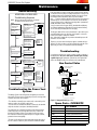
1
www.montigo.com fire feature Installation Operation & Maintenance Manual Check local codes and read all instructions prior to installation. C-View-PFC Fireplace BF-Series SSCustom Gas Fireplace C420 C520 C620 C720 C820 C820-PFC Shown Warning: Improper installation, adjustment, alteration, service or maintenance can cause injury or property damage. Refer to this manual. For assistance or additional information consult a qualified installer, service agency or the gas supplier. Safety Notice: Glass doors on gas fireplaces are extremely hot while the fireplace is on and remain hot even after the fireplace has been turned off. Safety screens are available and can reduce the risks of severe burns. For Your Safety: Do not store or use gasoline or other flammable vapors and liquids in the vicinity of this or any other appliance. ® C XG0706 US Canadian Heating Products Inc. Langley, BC V4W 4A Warning: What to do if you smell gas • • Do not try to light any appliance. Do not touch any electrical switch; do not use any phone in your building. • Immediately call your gas supplier from a neighbor's phone. Follow the gas supplier's instructions. • If you cannot reach your gas supplier, call the fire department. • Installer: Leave this manual with the appliance. • Consumer: Leave this manual for future reference. department. Montigo Del Ray Corp. Ferndale, WA 98248 022609 CVIEW-PFC Custom Gas Fireplace fire feature Warning: Read this manual before installing, operating or troubleshooting this appliance. Please retain this owner's manual for future reference. Congratulations Congratulations on selecting a FireFeature Custom gas fireplace, an elagent and well designed gas fireplace built to your specifications. The Firefeature gas fireplace you have selected is designed to provide the utmost in safety, reliability, and engineering standards. This owner's manual should be retained for future reference. We suggest that you keep it with all your other important documents and product manuals. As the owner of this new fireplace, you'll want to read and carefully follow all the instructions contained in this Installation, Operations and Maintenance manual. Pay special attention to all cautions, warnings, and Important warnings. Your new FireFeature Custom gas fireplace will give you years of durable, reliable use. Welcome to the FireFeature family of gas fireplace products. The information contained in this owner's manual, unless noted otherwise, applies to all models, and gas control systems. Safety Alert Key: • DANGER! Indicates a hazardous situation which, if not avoided will result in death or serious injury. • WARNING! Indicates a hazardous situation which, if not avoided could result in death or serious injury. • CAUTION! Indicates a hazardous situation which, if not avoided, could result in minor or moderate injury. • NOTICE: Used to address practices not related to personal injury. • Important: Used to address practices not related to personal injury. Table Of Contents Congratulations Safety Alert Key Introduction................................................................................ 3 Combustion Air Supply.................................................... 8 Warranty and Installation ............................................... 3 Electrical Schematic........................................................ 7 System Installation / Sequence of Operation.................. 3 Start Up Sequence.......................................................... 8 Installation Operation.................................................................................... 8 Installing the Fireplace.................................................4-5 Maintenance...................................................................... 11 - 13 Finishing around the Fireplace........................................ 6 General Observations................................................... 11 Framing.............................................................. 6 Cleaning........................................................................ 11 Fireplace Facing................................................. 6 Removing and installing the Door................................. 11 Mantels and Surrounds...................................... 6 Installing the glass beads and optional River Rock....... 12 Installing the Gas line...................................................... 6 Troubleshooting............................................................ 13 Installation of Electrical Supply....................................... 6 Gas Control Valve......................................................... 13 Exterior Power Vent Wire-Routing Installation................ 7 Spare Parts................................................................... 13 Installing the Remote Switch........................................... 7 Warranty................................................................................... 14 Vent Terminations............................................................ 7 Appentix A................................................................................. 15 Vent Installation............................................................... 9 Notes ...................................................................................... 16 Page 2 Part No. XG0706 CVIEW-PFC Custom Gas Fireplace fire feature Installation CAUTION! Due to its high operating temperatures, the appliance should be located out of traffic & away from furniture and draperies. Children and adults should be alerted to the hazards of the high surface temperature, which could cause burns or clothing ignition. Young children should be carefully supervised when they are in the same room as the appliance. Clothing or other flammable materials should not be placed on or near the appliance. Important: About the CVIEW-PFC Custom Gas Fireplace: The CVIEW-PFC is a linear burner power vented fireplace. Montigo's Power Vent system is ideal for extremely long or difficult venting runs, which are beyond the capability of a B-vent model. ■ The C420 is rated for Natural Gas and Propane at 100,000 BTU/H (29.2 Kilowatts) Input. Use 10" dia Certified manufactured B-Vent. ■ The C520 is rated for Natural Gas and Propane at 130,000 BTU/H (37.9 Kilowatts) Input. Use 10" dia Certified manufactured B-Vent. ■ The C620is rated for Natural Gas and Propane at 170,000 BTU/H (49.6 Kilowatts) Input. Use 10" dia Certified manufactured B-Vent. ■ The C720 is rated for Natural Gas and Propane at 200,000 BTU/H (58.4 Kilowatts) Input. Use 12" dia Certified manufactured B-Vent. ■ The C820 is rated for Natural Gas and Propane at 230,000 BTU/H (67.2 Kilowatts) Input. Use 12" dia Certified manufactured B-Vent. All dimensions, and design specifications are subject to approval upon quotation of fireplace and associated equipment. Part No. XG0706 Page 3 CVIEW-PFC Custom Gas Fireplace fire feature Installation Warranty and Installation Information: The Montigo warranty will be voided by, and Montigo disclaims any responsibility for, the following actions: Modification of the fireplace and/or components including vent assembly or glass doors. Use of any component part not manufactured or approved by Montigo in combination with this Montigo fireplace system. Installation other than as instructed in this manual. Consult your local Gas Inspection Branch on installation requirements for factory-built gas fireplaces. Installation & repairs should be done by a qualified contractor. Installations in Canada must conform to the current CAN/CGA B-149.1 and .2 Gas Installation Code and local regulations. This appliance must be electrically grounded in accordance with CSA C22.1 Canadian Electrical Code Part 1 and/or Local Codes. See Appendix A for installation within the State of Massachusetts. System Installation / Sequence of Operation Follow these instructions to ensure the safe and efficient operation of your Custom fireplace. All connections are to be made Per. the instructions within this Instruction Guide. Ensure the wall switch is turned to the “OFF” position. Installing The Fireplace To install the fireplace: The C-View fireplace system is an engineered fireplace system, and will require you to provide the correct vent run and air supply information to the Engineering staff of Montigo. Note: The C-View fireplace may be purchased as an open-front fireplace (no glass door), providing the the combustion air supply has been considered for the safe operation of the fireplace. Please consult with Montigo on the method which the volume of combustion air supply is to be delivered to the model of choice. C-View fireplaces with a glass front may also take the combustion air from the interior of the structure, and will be required to meet the requirements as one without a glass front. C-View fireplaces which use air from the exterior of the structure fall into the category of a ‘sealed combustion type appliance’. Fresh Air Supply: Connect all of the fresh air supply for this fireplace to the lower vent connections assuring no reduction or restriction to the air supply occurs, even due to unexpected circumstances. Please consider automated dampers, particularly on the intake air supply in cold climates. This is especialy important when the intake air is introduced from the top down. Cold air has the tendency to settle to the lowest point in the vent system. For extra long air supply runs, Montigo will recommend an increase in vent diameter. When changing the air supply from several incoming air connections to one vent, consult this information with your contact at Montigo. To ensure adequate operation of the vent system ensure the size of the one vent is not less than the total sum of vents that you are connecting to. Energize the electrical control panel. The Power Vent motor should run for three (3) minutes then automatically switch off. Flue Gas vent run: Turn the wall switch “ON”. The C-View fireplace system may be installed with any certified UL or ULC B-Vent. All the clearances to this B-Vent must be equivalent to the manufacture’s specifications as outlined in the installation/ operation manual. The size of this B-vent is specified in the approval process and cannot be reduced unless Montigo has re-evaluated your system. If authorized to reduce your vent size you will be issued new shop drawings reflecting the new vent connection size and specifications. The vent system may be installed vertically or horizontally, to any length, and may have numerous elbows. (Quantity of elbows as supplied to Montigo). The vent run may also be lower than the fireplace flue gas outlet, or have a portion that is lower than the main vent run, as long as Montigo has reviewed and engineered the entire system. Montigo will then re-evaluate this information and size the Power Vent to the vent restriction, and compensate for the pressure drop. The power vent motor will start to run and develop a negative pressure in the vent above the gas flue outlet. (This negative pressure is monitored by a pressure switch located in the bottom of the fireplace). When this negative pressure exceeds 0.02" WC, the switch will close the connection on terminal strip #9 and #10 located in the electrical panel. This will power up both relays supplying 24 Volts to the Honeywell control valves located in the bottom of the fireplace. The glow pug on the pilot system will ignite the pilots, and the sensor will identify the presence of a pilot flame and turn the gas valve to fully open position. In the event that a pilot can not be established the electronic monitoring system in the smart valve will repeat this process three times. If the system is not successful in the third attempt the valve will lock out. To reset the system turn the wall switch “off”, and then switch back “ON” to repeat this sequence. Should the system NOT ignite, read the trouble shooting section for additional information. Important: All dimensions, and design specifications are subject to approval upon quotation of fireplace and associated equipment. Page 4 Power Vent: Montigo manufactures a variety of Power vent modules as large as 5KWatts. The Power vent is commonly placed either horizontally or vertically at the end of the B-Vent run. However, we have an in-line vent module available. This Inline Power vent is for installations where an exterior module isn’t visually attractive, or permitted. Also, In-line Power vents are more complex to install, primarily due to the positive pressure in the vent system after the Power vent module. Therefore this vent run after the Power vent module must be air-tight due too the concern gas by-products may leak from the vent into the structure. All Power vent modules create a negative pressure before the module and leaks in the vent draw air from the building and will not create a safety hazard. Part No. XG0706 CVIEW-PFC Custom Gas Fireplace fire feature Installation C-View fireplace: C-View-PFC Fireplace Dimensions The fireplace may be installed in any location that maintains proper clearances to air conditioning ducts, electrical wiring and plumbing. Safety, as well as efficiency of operation, must be considered when selecting the fireplace location. Try to select a location that does not interfere with room traffic, has adequate ventilation, and offers an accessible pathway for vent installation. Refer to Vent Installation Section for more information. A B C D E F G H I J K L C420 54 56 24 10 26 N/A N/A N/A N/A 8 24 N/A M N N/A 153/8 N/A N/A C520 N/A N/A N/A N/A N/A N/A N/A N/A N/A N/A N/A N/A C620 N/A N/A N/A N/A N/A N/A N/A N/A N/A C720 N/A N/A N/A N/A N/A N/A N/A N/A N/A N/A N/A N/A N/A N/A N/A N/A N/A N/A N/A C820 114 36 8 5/8 565/8 N/A N/A N/A N/A 18 3/4 N/A N/A 76 42 17 Figure 1a. Fireplace dimensions. (Contact the manufacturer for all dimensions for models C520 through C720). The fireplace dimensions are shown below and on the following page: C-View-PRC Air Intake Dimensions A O Qty of Vent s E D Intake Air Exhaust P Dia. of Vents 6 7/8 Rear 7 1/8 Bottom C420 2 C520 C620 N/A N/A N/A N/A N/A N/A C720 N/A N/A N/A C820 3 6 7/8 Rear 7 1/8 Bottom Air Intake in/sq Call Call Call Call Call Figure 2. Air Intake dimensions. (Contact the manufacturer for all dimensions for models C520 through C720). K Optional Intake N B Note: Intake air for combustion of the C-View system, may originate from within or from the exterior of the structure. For installations where the combustion air intake ducts are not connected to the exterior of the structure ensure there is adequate fresh air in the interior space. E To operate efficiently, C-View gas fireplaces (with glass doors) require 80CFM per. 10,000 BTU's. Open face units require the specified 100CFM per. 10,000BTU of fresh air to operate properly. Front View Clearances J P All building materials that are shaded in Figure 3 must be non-combustible materials. The C-View-PFC must also maintain the following clearances. D C Side View Top of 90 Elbow (BV) 1" Top of 90 Elbow (CV) 3" Vent 1" Sides 2" Back 2" Mantel(s)* 12" Door** 1/4" Top 24" Floor 0" * See Instructions on page 4 ** See Instructions on page 4 Unprotected combustible walls which are perpendicular to the fireplace opening, must not be closer to the fireplace than the described in Figure 7. Figure 1. Fireplace dimensions. WARNING! When this appliance is installed directly on carpeting, tile or any combustible material other than wood flooring, it must be installed on a metal or wood panel extending the full width and depth of the appliance. Part No. XG0706 Page 5 CVIEW-PFC Custom Gas Fireplace fire feature Installation Framing R Finishing Around the Fireplace Q Use Non-combustable materials, as shown Structure framing Note: always check your dimensions prior to installation. U Combustible mantels and mouldings may be safely installed over the fireplace provided that they do not project beyond shaded area shown in Figure 4. Side wall clearances are 3". Combustible surrounds may be installed with 3" clearance to the side of the fireplace as shown in Figure 5. Fireplace Facing When selecting the finish material for your fireplace, it is important to remember the following: THE ELECTRICAL CONTROL PANEL MUST NOT BE OBSTRUCTED IN ANY WAY - to do so prevents access for servicing controls. The face of the fireplace may be painted to match the room decor, provided you use a heat-resistant paint. Decorative facing must not extend past the fireplace opening at all, because it will interfere with the access to retainers for removal of glass door. Finished floor Figure 3. Framing dimensions Framing Dimensions Q R U C420 57 1/8 23 56 3/8 C520 N/A N/A N/A C620 N/A N/A N/A C720 N/A C820 113 N/A 36 76 1/2 3-Sides Typical. Use non-combustible Materials N/A 6” Figure 3a. Framing dimensions. (Contact the manufacturer for all dimensions for models C520 through C720). Framing the Door Figure 4. Combustible mantles and facing's (Both Sides Typical). Mantels & Surrounds /2 1 NOTE: National Canadian Gas Association mantel test requirements are for fire hazard prevention to combustible materials. /8 3 New technology, to meet consumer and government demands for the wise use of energy, has prompted us to manufacture many models of fireplaces which are hot, fuel and energy efficient. Please be aware; temperatures over the mantel will rise above normal room temperature and walls above fireplace may be hot to touch. We recommend careful consideration be given to the effects of elevated mantel temperatures which may be in excess of product design, for example: candles, plastic or pictures. This can cause melting, deformation, discoloration or premature failure of T.V. and radio components. Figure 3a. Door framing dimensions. (Typical). Painting: Refer to chart on page 3a for correct dimensions. Finish drywall up to outside dimensions Q, and U. Use non combustible J-track to finish edge of drywall. This will leave a 1/4" opening to allow the CVIEW Door Frame to be slid into place. Special care is recommended by the Master Painters and Decorators Association, when painting the fireplace surrounds, to select and apply a quality Alkyd sealer prior to the applying of latex paints. This is to prevent leaching of water from evaporation and causing a brownish staining effect to paint over coats. Page 6 Part No. XG0706 CVIEW-PFC Custom Gas Fireplace fire feature Installation Installation Of Electrical Supply 6” MIN The C-View Fireplace is supplied with an external electrical Control Panel pre-wired by the factory. The standard gas control cable is 15 feet between the fireplace and the external panel, additional length is available upon request. The external panel is 16" x 16" x 6" and must be located in an accessible location. The C-View requires 120V electrical supply on a dedicated 15 amp fuse or circuit breaker to the Control Panel Installations in Canada must be electrically grounded in accordance with CSA C22.1 Canadian Electrical Code Part 1 and/or Local Codes. Installations in the USA must be electrically grounded in accordance with local codes or, in the absence of local codes, with the National Electrical Code, ANSI/NFPA 70-1987. 110V Power Supply Fuse Figure 5. Combustible surrounds. Post Purge Control Installing The Gas Line The gas connection is located on the right side of the lower portion of the fireplace body. The manufacturer requires a service shut off valve located in an accessible location to isolate the gas supply. The gas line must be installed, and tested for leaks before finishing the CVIEW Fireplace. Natural Gas requires a minimum inlet gas supply pressure of 5.5" W.C. & a manifold pressure of 3.5" W.C. Propane requires a minimum inlet gas supply pressure of 11" W.C. & a manifold pressure of 10" W.C. The manifold outlet pressure is set from the factory to the appropriate pressure and should be verified. The manufacturer has provided an inlet pressure tap location in the fireplace for easy access. The control valves have a provision to remove a 1/8 plug so that a hose barb fitting can be installed to check pressure. Note: After gas line is connected, each appliance connection, valve and valve train must be checked while under normal operating pressure with either a liquid solution, or leak detection device, to locate any source of leak. Tighten any areas where bubbling appears or leak is detected until bubbling stops completely or leak is no longer detected. DO NOT use a flame of any kind to test for leaks. LP or NG Gas Hookup 1/2”NPT 2 1/2” Electrical Connection to Service Panel 2 1/2” Power Vent Motor Gas Control Wiring Wall Switch Air Proving Switch Fan Speed Control Figure 7. Electrical Supply The electrical panel has three connection boxes on the side of the panel marked: 110 Volt Power Supply, Power Vent Motor, and Gas Control Wiring. First Connect the White, Black, and Green (Ground) wire coming from the power vent motor in the box marked Power Vent Motor. Then connect the cable from the fireplace. Last connect the power supply to the box marked 110 Volt Power Supply. See the diagram on page 9 for the cable installation. Installing The Remote Switch The CVIEW-PFC's two gas valves, located inside the unit and underneath the burner, may be connected to a wall switch or a hand-held remote. The valve operates on a 24V circuit. DO NOT connect the gas valve to an external circuit. The external electrical panel supplied with the fireplace is equipped with a 20 foot low voltage wire, for connecting to a wall switch of your choice, longer lengths are an option. CAUTION: 15” 3 1/4” Refer to chart on page 3 for correct dimensions. Figure 6. Gas line access. Part No. XG0706 Do not obstruct, or attempt to conceal, the vent termination. These actions will affect the operation of the fireplace, and may be hazardous. In heavy snow areas, take extra care to prevent snow buildup from obstructing the vent termination. Page 7 CVIEW-PFC Custom Gas Fireplace fire feature Installation Exterior Power Vent / Wire Routing Installation Diagram Power Vent Termination For vertical installations the longest vent run is 140 feet with a limit of 8 -90° Elbows, or 16 - 45° Elbows. For longer runs contact the C-View Manufacturer. For horizontal installations the longest vent run is 100 feet with a limit of 4 -90° Elbows, or 8 - 45° Elbows. For longer runs contact the C-View Manufacturer. It is important that the location of the power vent motor is not exposed to a downfall of water not in excess of the standard rain fall. For Exterior Power Vent Installations use EXPVRN10 or EXPVRN12 or for extra long vent runs use BF52 Power Vent Module. Available BF-Series Exterior Power Vent Systems: One Control Cable Installation required for either Horizontal or Vertical Termination. Montigo BF-Series Exterior Power Vent Systems Power Vent model BFPVRN 10/12 Power Vent Termination BFPVWN 10/12 16”x 16”x 4” Deep Elect. Control Box Inlet Exhaust BFPVDWN 10/12 BFPVRNB 10/12 BFPVDRNB 10/12 110 VAC 15A Supply Current From Dist. Panel To Control Box 20’ Foot, 10-Conductor Cable to Fireplace, (Standard) From ControlBox BFPVWNB 10/12 Selecting A Termination Location Before installing the termination or venting, check to ensure the planned termination location is acceptable. See figure 10, 10a below. Installing ST Terminations with Frame 110 1/3 1.4A 1,150 1,600 Roof 220 Roof 220 Wall 220 1/3 1.5A 1,150 1,600 1/3 1.5A 1,150 1,600 1/3 1.5A 1,150 1,600 NA NA NA NA BFPVWH 10/12 Roof 220 1-1/2 5.6A 1,750 6,000 Wall 220 1-1/2 5.6A 1,750 6,000 NA BFPVDRH 10/12 Vent Terminations 110 Wall Wall NA Wall 220 1/3 1.5A 1,150 1,600 Roof 220 1-1/2 5.6A 1,750 6,000 BFPVDWNB 10/12 BFPVRH 10/12 Figure 7a. C-View Control Box / Power Vent Wire Routing Diagram Amp RPM CFM Damper 10”12” 1/3 1.4A 1,150 1,600 1/3 1.4A 1,150 1,600 1/3 1.4A 1,150 1,600 Roof 110 Roof 110 BFPVDRN 10/12 Cable to Power Vent (Horizontal Installation) Mount VOLT HP BFPVDWH 10/12 Wall 220 1-1/2 5.6A 1,750 6,000 BFPVRH5 10/12 Roof 220 5 12.0A 2,200 10,000 BFPVDRH5 10/12 Roof 220 5 12.0A 2,200 10,000 BFPVWH5 10/12 Wall 220 5 12.0A 2,200 10,000 BFPVDWH5 10/12 Wall 220 5 12.0A 2,200 10,000 NA NA Available Exhausto Exterior Power Vent Systems: Exhausto Exterior Power Vent Systems 1. Frame the termination opening to 22" x 22". Power Vent model Model Mount VOLT HP 2. Fasten the termination and its frame using a minimum of 4 screws. (See Figure 8, 8a) EXPVRN 10/12 1/3 1.4A 1,400 1/3 1.4A 1,400 NA EXPVDRN 10/12 RS14 Roof 110 RS14 Roof 110 RS16 Roof 110 RS16 Roof 110 1/3 3.9A 2,000 1/3 3.9A 2,000 NA 1/3 1.4A 1,400 1/3 1.4A 1,400 1/3 3.9A 2,000 110 1/3 3.9A 2,000 NA Exterior Power Vent Installation EXPVRH 10/12 EXPVDRH 10/12 Installation Requirements for Exterior Power Venter EXPVDWN 10/12 The CVIEW-PFC fireplaces are certified for use with any approved UL certified B-Vent venting components. (Use of other non-certified parts will void the Montigo warranty, and may impede the operation of the fireplace). EXPVWH 10/12 RS14 Wall 110 RS14 Wall 110 RS16 Wall 110 EXPVDWH 10/12 RS16 Wall EXPVWN 10/12 Amp CFM Damper 10”12” NA The clearance for B-Vents is listed by the manufacturer of the B-Vent. Install components and fittings using the clearances specified by the B-Vent manufacturer . All joints must be secured as per the instructions provided by the B-Vent manufacturer. The exhaust portion of a vent termination must not be recessed in a wall cavity. Horizontal runs must be supported by a minimum of three supports per 10 feet of venting. Page 8 Part No. XG0706 CVIEW-PFC Custom Gas Fireplace fire feature Installation 22” Power Vent Termination Termination Power Vent Frame, Min. 22”x 22” box 12” B-Vent Slip Section Power Vent Frame, Min. 22”x 22” box 22” 12”Min Height 12”Min Height 22” 22” 10” Flexible Duct, One run for Horizontal or Vertical 10” Flexible Vent Installation Required. 10” Flexible Duct, One run for Horizontal or Vertical Installation Required. Exhausto Model RSIF 160/180 Power Vent Power Vent Termination Power Vent Frame Min. 1” Clearance around Horizontal Venting as per. Montigo Flexible Vent specifications. Max. 30’ feet horizontal Venting with 3-elbows. Seal at both ends with high temperature sealant. Top and Top Inlet Top Exhaust 10” B-Vent Section. Vertical Vent Runs over 30’ contact C-View Manufacturer Min. 1” Clearance around Horizontal Venting as per. Montigo Flexible Vent specifications. Max. 30’ feet horizontal Venting with 3-elbows. Seal at both ends with high temperature sealant. Top and bottom inlet Typical. bottom inlet Typical. Bottom Inlet (Alt) Bottom Inlet (Alt) Figure 8. Typical B-vent configurations. Installation Requirements for Interior Power Venter, Model: Exhausto RSIF 160/180/300/350/400/500 Vent size used will depend solely on Gas Fireplace model number, size of unit. C-View Models 520-920 will use 10"diameter B-Vent, with C-View Models 1020-1620 using 12"diameter B-Vent. C-View Gas Fireplaces are certified for use with any approved UL Certified B-Vent, supplied from fireplace to In-line Power Vent Module. A flexible insulated Vent pipe manufactured and listed by Montigo will connect the Power Vent Module to the termination. All joints between the Power Venter and Termination must be sealed air-tight with silicon or approved equal. The flexible portion of insulated pipe must have 1" clearance to all combustibles. Top Inlet Top Exhaust 10” B-Vent Section. Vertical Vent Runs over 30’ contact C-View Manufacturer Figure 8a. Typical Flexible vent configurations. Combustion Air Supply System Installation Requirements An intake grill will have to be installed with the same size of the total opening as the combined air supply ducts on the unit. Make sure you have calculated the restriction and selected the proper grill size. The C-View fireplace is supplied with two or more combustion air duct connection points. Do not reduce the size of the air supply system, or restrict the air supply in any way. On any combustion air supply run longer than 25 feet the duct should be increased in size to prevent a restriction. A vacuum safety switch, located under the burners, will monitor the combustion air supply pressure and will prevent the burner from igniting, or continuing to burn if the pressure is negative, past 0.3WC. For air supply runs over 25 feet consult with Montigo to have the vent supply re-sized. Inlet Vent Exhaust Figure 10c. Combustion Air Supply Vent . Part No. XG0706 Page 9 CVIEW-PFC Custom Gas Fireplace fire feature Installation WARNING! If you do not follow these instructions exactly, a fire or explosion may result causing property damage, personal injury or loss of life. 110V Power Supply 6 Amp 110V Fuse PostPurge Purge Control Post Control 110V Motor R G B B R R W To Fireplace W Bk Bk W W Bk G Bk 110V 110V 24V 24V Motor Speed Control R2 R1 G B Valve 1 Page 10 Valve 2 Wall Switch Red 8 9 10 Brn Red 7 Red 6 Jumper Org 5 Blu Yel 3 4 Pk 2 Wall Switch Blk / Wht 1 Relay Blu / Yel Denotes Low Voltage Denotes Line Voltage Blk / Wht Yel Legend Wht / Blk First Burner: 1,2 Black-White Second Burner: 3,4 Blue-Yellow Wall Switch: 6,7 Black-White Air Priority Switch: 9,10 Orange-Red Green is Ground Relay LVT To Wall Switch Blu O R Wht / Blk P LVT Y W Bk Y Yel Bk W B Y Blk / Yel Y Yel Y Air Proving Switch Part No. XG0706 CVIEW-PFC Custom Gas Fireplace fire feature Installation WARNING! If you do not follow these instructions exactly, a fire or explosion may result causing property damage, personal injury or loss of life. Startup Sequence: A. Purge all air out of the gas supply line to the fireplace system and ensure that the supply pressure is not in excess of 12" WC. B. Ensure the supplied Power vent module is connected to the with the ON/Off switch in the Off position. The power vent motor should start up, and time out in about 3 to 5 minutes. Make sure that the power vent motor is running clock wise by looking at the motor end. 2. Turn the speed controller now to the low speed (clock wise). electrical control panel. C. Ensure the wall switch terminals inside the Power vent 3. Switch on the fireplace, and slowly turn the speed up on control box are connected to the single pole ON/ Off switch. 1. Turn the speed controller to the high position, (counter clock wise). When you feel a click you have turned the power vent motor to the Off position. Initiate power to the control panel the power vent module until the hot service igniters start to glow. Leave the speed at that setting. Control panels with two relays will make a clicking sound when the the air switch turn's the system on. CAUTION! This fireplace has been set up at the factory for a determined air volume though the venting system. This fireplace will not operate unless the correct air movement is detected by our control system. The glass temperature should not exceed 300 deg F. and the flue gas temperature should not exceed 380 deg F. Please consulted with your contact person at Montigo should you have any problems with your start up. Operation: With Honeywell Intermittent Pilot WARNING! If you do not follow these instructions exactly, a fire or explosion may result causing property damage, personal injury or loss of life. For Your Safety - READ BEFORE LIGHTING: A. This appliance is equipped with an ignition system that lights the pilot burner automatically. Do not attempt to light the pilot by hand. B. BEFORE LIGHTING smell all around the appliance area for gas. Be sure to smell next to the floor because some gas is heavier than air and will settle on the floor. What To Do If You Smell Gas: Do not try to light any appliance. Do not touch any electrical switch; do not use any phone Part No. XG0706 in your building. Immediately call your gas supplier from a neighbour's phone. Follow the gas supplier's instructions. If you cannot reach your gas supplier, call the Fire Department. C. Do not use this appliance if any part has been under water. Immediately call a qualified service technician to inspect the appliance and to replace any part of the control system, and any gas control which has been under water. Page 11 CVIEW-PFC Custom Gas Fireplace fire feature Maintenance CAUTION! Fireplace gas control must be in the “OFF” position and pilot and main burners extinguished when cleaning appliance with a vacuum. Doors can get very hot. Handle only when cool. General Have the fireplace installation inspected yearly, including a visual check of the vent system, the burner and the pilot flame. For your convenience a 1/8" manifold pressure tap is supplied on the gas valve for a test gauge connection. Removing and Installing the Door Removing the door: The C-View-PFC Series Door-Window outer trim are held in place by magnets, and the Door-window frames are held in place by fine-thread 10-24 screws. Follow the process below to remove, or install the items described. Figure 14. The Fireplace as it is received from Montigo. Figure 15. (Step 2) Remove the Door-window trim by grasping the metal firmly and pull it free it from the frame. Note: Hold it as shown in Step 2 to release the hold of the magnets. For Natural Gas this appliance requires a minimum inlet pressure of 5.5" W.C. and a manifold pressure of 3.5" W.C. For Propane this appliance requires a minimum inlet pressure of 11" W.C. and a manifold pressure of 10" W.C. Always keep the fireplace area clear and free of combustible materials, as well as gasoline and other flammable vapours and liquids. Do not use this appliance if any part has been under water. Immediately call a qualified service technician to inspect the appliance and to replace any part of the control system and any gas control which has been under water. Cleaning When the fireplace is first activated, there may be some smoking and a visible film may be left on the glass. This is a normal condition, and is the result of burning of protective coatings on new metal. Figure 14. Step 1. (Door Trim ) Figure 15. Step 2. (removal of Trim) Glass must be cleaned periodically to remove any film (which is a normal by-product of combustion) which may be visible. Film can easily be removed by removing the door, as shown on page 8. Handle the door carefully, and clean it with non-abrasive glass cleaners. One of the most effective products is Kel Kem. Silicone seals on inner door during initial firing will "off gas", leaving a visual deposit of a white substance on combustion chamber walls. This can easily be removed using normal household products. Use a vacuum cleaner or whisk broom to keep the control compartment, burner, and firebox free from dust and lint. WARNING! Do not attempt to clean glass when hot. Figure 16. Step 3 (Removal of Do not clean glass with abrasive materials as any glass etching may cause premature glass failure. Figure 16. (Step 3) Remove the Door-window assembly by turning the 10-24 screws counterclockwise. Note: Have someone hold the doorwindow assembly in place until all screws are removed. Then grab the assembly from either end lifting it away from the fireplace. Place it in a safe location to store or clean. Door Frame) Figure 17. (Completed Re- moval) Figure 17. (Step 4) Removal is complete. Proceed with service or cleaning. Page 12 Part No. XG0706 CVIEW-PFC Custom Gas Fireplace fire feature Maintenance installing the doors: Install the doors in reverse order as shown in Steps 1 through 4. Important: when re-installing screws into their original location, ALWAYS hand tighten with screwdriver to ensure proper tension on all screws. CAUTION! DO NOT OVERTIGHTEN with an electric appliance (Screwdriver). Most electric drills, or turning device's have torque settings, and if this setting is set too high it will strip the threads in the inserts. See the procedure above for re-installing the door. Installing the Glass Beads and Optional River Rocks CAUTION! DO NOT OPERATE THIS FIREPLACE WITHOUT THE GLASS DOOR OR WITH A BROKEN GLASS DOOR. CAUTION! Fireplace gas control must be in the “OFF” position and pilot and main burners extinguished when cleaning appliance with a vacuum. Doors can get very hot. Handle only when cool. Beads The C-View-PFC Series are supplied with Designer Glass beads. Remove the Door and trim as shown in the previous Instruction. Follow these instructions to ensure all parts are removed or replaced as required. Once the Trim and glass door are removed place the marbles randomly across the pan surrounding the burners as shown in Figure 18. WARNING! Do not attempt to clean glass when hot. Do not clean glass with abrasive materials as any glass etching may cause premature glass failure. NOTE: DO NOT Cover burners with beads or the optional rocks as shown in Figure 18. Figure 18. Installation of glass beads . Optional River Rocks The C-View-PFC Series has the option of installing the optional cultured rocks which mimic real stone. They are attrative yet designed to withstand a high temperature environment such as inside a gas fireplace. These may be spaced at random, or in a visual pattern of your preference. See the Montigo web site for photographs and ideas. www.montigo.com Note: Ensure the rocks or beads do not cover the Burners. Part No. XG0706 Page 13 6 Amp 110V Fuse CVIEW-PFC Custom Gas Fireplace P fire feature 110V Motor Maintenance Troubleshooting G NOTE: Before Troubleshooting, Familiarize Yourself With The Startup And Checkout Procedure. NO YES NO YES Turn gas on. Pilot Burner Lights? NO YES SYSTEM OK NO Replace SV9500/ SV9600 NO Measure Volume to SV9500 / SV9600 Voltage must be at least 19.5 VAC Bk W B Y W Bk Troubleshooting NO YES Check Transformer Line Volt Supply Replace Igniter / Flame Rod Assembly and retain. Restart troubleshooting Sequence. Does main valve open? YES O R P B Legend Denotes Low Voltage Denotes Line Voltage If your fireplace still does not operate correctly, consult your dealer or Note:be performed by the manufacturer. All service and repairs should Remove Jumper to install Switch a qualified agency. All spare parts, optional fans, and optional trim finishes are available from your local dealer or the manufacturer. Honeywell (Q3450) Pilot Assembly NO Pilot Electrical Harness Connector Replace SV9500 / SV9600. Save old Igniter/ Flame Rod Assembly for service. Valve Honeywell Gas Control (SV9501M) Discard old Igniter / Flame Rod Assembly The Montigo Power Venter will generate a negative pressure in the vent system. This pressure is monitored by a pressure sensing switch located in the bottom of the fireplaces. • The switch has a normally open contact and is connected by a nine conductor cable to the electrical control panel. • The two wires are red and brown and are connected to the terminal strip in the electrical control panel, terminal, #9 and #10. The combustion air is supplied to the bottom of the fireplace and is monitored by a pressure sensing switch that is also located in the bottom of the fireplace. If there is a shortage of air for any reason, the combustion air monitoring switch will open, closing the contacts, prevent the burner from igniting. •The wires for this switch are orange and purple and are also part of the nine conductor cable; they are connected to terminal #7 and #8. Rela Gas Control Valve Replace Igniter / Flame Rod Assembly NO Mot C Therefore; you must remove the fireplace glass to eliminate this possibility. To If you Wallstill do not have a closed circuit after the removal of the glass front you need to consult with a technician at Montigo. Switch Gas Control Connector Troubleshooting the Power Vent System: Page 14 24V Y Y Y The flue gas switch will close the contact when it is exposed to aYpressure differential from the top of the flue of the fireplace, vs from the bottom of the fireplace combustion chamber. Note: A blocked air supply will not provide a substantial pressure differential to close the switch. Replace Igniter / Flame Rod Assembly Replace SV9500/SV9600 YES Main Valve opens? Unplug Pilot Burner Cable, Measure Voltage at SV9500/SV9600 HSI Terminals (24VAC Nominal, see INSET) 110V 24V YES Igniter warms up and glows red. Pilot Valve opens. HSI - Line voltage power Terminals - Low voltage transformer - Limit Controller - Thermostat - Wiring - Air proving switch on combustion air blower system -Vent damper (if used) is open and end switch made 110V R R Wht / Blk SV9500 / SV9600 is powered (24VAC nominal) INSET CHECK: - Turn Gas Supply Off - Set thermostat to call for heat W Bk In the event that you need to test the status of both pressure W Bk switches, you would remove the jumper on terminal # 8 and # 9, so that you can test with an ohm meter on terminal’s #7 and #8. You can also check B B W the terminals number #9 and #10 without a power feedback. Bk Note: • Test these switches with the power vent motor in operation at maximum speed. You should have a closed circuit on both switches. • An open contact on the combustion air proving switch, (terminals #7 and #8) will indicate a lack of air supply. • An open contact on the flue gas switch, (terminals #8 and #9) may also indicate inadequate air flow at theR1flue outlet however that may To Fireplace R2 also be caused by an inadequate fresh air supply. G Yel HONEYWELL SV9500 /9600 Troublshooting Sequence START R R W Bk Figure 11. Honeywell SV9501 gas valve. Spare Parts - CVIEW-PFC PART NUMBER NG Gas Valve RGC1004 NG Pilot RGC2021 Door Contact the Manufacturer Proving Switch REC1168 Relay EC1170 Tansformer REC1142 Part No. XG0706 CVIEW-PFC Custom Gas Fireplace fire feature Warranty The Warranty The Companies warrants the Montigo Gas Appliance to be free from defects in materials and workmanship at the time of manufacture. On the Montigo, there is a tenyear warranty on the firebox and its components, a five-year warranty on the main burner, and a one-year warranty on the pilot burner, gas control valve and fibre logs. Glass, plated/painted finishes, and refractory lining are exempt. Remedy And Exclusions The coverage of this Warranty is limited to all components of the Gas Appliance manufactured by The Companies. This Warranty only covers Montigo Gas Appliances installed in the United States or Canada. If the components of the Gas Appliance covered by this Warranty are found to be defective within the time frame stated (see The Companies right of investigation outlined below). The Companies will, at its option, replace or repair defective components of the Gas Appliance manufactured by The Companies at no charge, and will also pay for reasonable labour costs incurred in replacing or repairing components. If repair or replacement is not commercially practical, The Companies will, at its option, refund the purchase price of the Montigo Gas Appliance. This Warranty covers only parts and labour as provided above. In no case shall The Companies be responsible for materials, components, or construction which are not manufactured or supplied by The Companies, or for the labour necessary to install, repair or remove such materials, components or construction. All replacement or repair components will be shipped F.O.B. the nearest The Companies factory. Qualifications To The Warranty The Gas Appliance Warranty outlined above is further subject to the following qualifications: (1) The Gas Appliance must be installed in accordance with The Companies installation instructions and local building codes. The Warranty on this Montigo Gas Appliance covers only the component parts manufactured by The Companies. The use of components manufactured by others with this Montigo Gas Appliance could create serious safety hazards, may result in the denial of certification by recognized national safety agencies, and could be in violation of local building codes. This warranty does not cover any damages occurring from the use of any components not manufactured or supplied by The Companies (2) The Montigo Gas Appliance must be subjected to normal use. The Gas Appliances are designed to burn gas only. Burning conventional fireplace fuels such as wood, coal or any other solid fuel will cause damage to the Gas Appliance, will produce excessive temperatures and will result in a fire hazard. Limitations On Liability It is expressly agreed and understood that The Companies sole obligation, and purchaser's exclusive remedy under this Warranty, under any other warranty, expressed or implied, or in contract, tort or otherwise, shall be limited to replacement, repair, or refund, as specified above. In no event shall The Companies be responsible for any incidental or consequential damages caused by defects in its products, whether such damage occurs or is discovered before or after replacement or repair, and whether or not such damage is caused by The Companies negligence. Some states do not allow the exclusion or limitation of incidental or consequential damages, so the above limitation or exclusion may not apply to you. The duration of any implied warranty with respect to this Montigo Gas Appliance is limited to the duration of the foregoing warranty. Some states do not allow limitation on how long an implied warranty lasts, so the above may not apply to you. Investigation Of Claims Against Warranty The Companies reserves the right to investigate any and all claims against this Warranty and to decide upon method of settlement. The Companies Are Not Responsible For Work Done Without Written Consent The Companies shall in no event be responsible for any warranty work done without first obtaining The Companies written consent. Dealers Have No Authority To Alter This Warranty The Companies employees and dealers have no authority to make any warranties nor to authorize any remedies in addition to or inconsistent with those stated above. How To Register A Claim Against Warranty In order for any claim under this Warranty to be valid, The Companies must be notified of the claimed defect in writing or by telephone, as soon as reasonably possible after the defect is discovered. Claims against this Warranty in writing should include the date of installation, and a description of the defect. Other Rights This Warranty gives you specific legal rights, and you may also have other rights which vary from state to state. NOTE: The Companies as stated above refer to - Canadian Heating Products Inc. and/or Montigo Del Ray Corp. Canadian Heating Products Inc. and/or Montigo DelRay Corp. reserves the right to make changes at any time, without notice, in design, materials, specifications, prices and also to discontinue colors, styles and products. Part No. XG0706 Page 15 CVIEW-PFC Custom Gas Fireplace fire feature Appendix A - State of Massachusetts Amendment (Gas Fireplace / Equipment sold in the State of Massachusetts) 5.08: Modifications to NFPA-54, Chapter 10 (1) Revise NFPA-54 section 10.5.4.2 by adding a second exception as follows: Existing chimneys shall be permitted to have their use continued when a gas conversion burner is installed, and shall be equipped with a manually reset device that will automatically shut off the gas to the burner in the event of a sustained back-draft. (2) Revise 10.8.3 by adding the following additional requirements: (a) For all side wall horizontally vented gas fueled equipment installed in every dwelling, building or structure used in whole or in part for residential purposes, including those owned or operated by the Commonwealth and where the side wall exhaust vent termination is less than seven (7) feet above finished grade in the area of the venting, including but not limited to decks and porches, the following requirements shall be satisfied: 1. INSTALLATION OF CARBON MONOXIDE DETECTORS. At the time of installation of the side wall horizontal vented gas fueled equipment, the installing plumber or gas fitter shall observe that a hard wired carbon monoxide detector with an alarm and battery back-up is installed on the floor level where the gas equipment is to be installed. In addition, the installing plumber or gas fitter shall observe that a battery operated or hard wired carbon monoxide detector with an alarm is installed on each additional level of the dwelling, building or structure served by the side wall horizontal vented gas fueled equipment. It shall be the responsibility of the property owner to secure the services of qualified licensed professionals for the installation of hard wired carbon monoxide detectors a. In the event that the side wall horizontally vented gas fueled equipment is installed in a crawl space or an attic, the hard wired carbon monoxide detector with alarm and battery back-up may be installed on the next adjacent floor level. b. In the event that the requirements of this subdivision can not be met at the time of completion of installation, the owner shall have a period of thirty (30) days to comply with the above requirements; provided, however, that during said thirty (30) day period, a battery operated carbon monoxide detector with an alarm shall be installed. 2. APPROVED CARBON MONOXIDE DETECTORS. Each carbon monoxide detector as required in accordance with the above provisions shall comply with NFPA 720 and be ANSI/UL 2034 listed and IAS certified. 3. SIGNAGE. A metal or plastic identification plate shall be permanently mounted to the exterior of the building at a minimum height of eight (8) feet above grade directly in line with the exhaust vent terminal for the horizontally vented gas fueled heating appliance or equipment. The sign shall read, in print size no less than one-half (1/2) inch in size, “GAS VENT DIRECTLY BELOW. KEEP CLEAR OF ALL OBSTRUCTIONS”. 4. INSPECTION. The state or local gas inspector of the side wall horizontally vented gas fueled equipment shall not approve the installation unless, upon inspection, the inspector observes carbon monoxide detectors and signage installed in accordance with the provisions of 248 CMR 5.08(2)(a)1 through 4. (b) EXEMPTIONS: The following equipment is exempt from 248 CMR 5.08(2)(a)1 through 4: 1. The equipment listed in Chapter 10 entitled “Equipment Not Required To Be Vented” in the most current edition of NFPA 54 as adopted by the Board; and 2. Product Approved side wall horizontally vented gas fueled equipment installed in a room or structure separate from the dwelling, building or structure used in whole or in part for residential purposes. (c) MANUFACTURER REQUIREMENTS - GAS EQUIPMENT VENTING SYSTEM PROVIDED. When the manufacturer of Product Approved side wall horizontally vented gas equipment provides a venting system design or venting system components with the equipment, the instructions provided by the manufacturer for installation of the equipment and the venting system shall include: 1. Detailed instructions for the installation of the venting system design or the venting system components; and 2. A complete parts list for the venting system design or venting system. (d) MANUFACTURER REQUIREMENTS - GAS EQUIPMENT VENTING SYSTEM NOT PROVIDED. When the manufacturer of a Product Approved side wall horizontally vented gas fueled equipment does not provide the parts for venting the flue gases, but identifies “special venting systems”, the following requirements shall be satisfied by the manufacturer: 1. The referenced “special venting system” instructions shall be included with the appliance or equipment installation instructions; and 2. The “special venting systems” shall be Product Approved by the Board, and the instructions for that system shall include a parts list and detailed installation instructions. (e) A copy of all installation instructions for all Product Approved side wall horizontally vented gas fueled equipment, all venting instructions, all parts lists for venting instructions, and/or all venting design instructions shall remain with the appliance or equipment at the completion of the installation. (3) After NFPA-54 section 10.10.4.2 add a new section 10.10.4.3 as follows: When more than four gas appliances are to be vented through a common gas vent or common horizontal vent manifold, a plan of the proposed vent installation shall be submitted to the Inspector and the serving gas supplier for review and approval. Extraction from: Massachusets Rules and Regulations 5.00: Amendments To 2002 Edition Of ANSI Z223.1-NFPA-54 Page 16 Part No. XG0706 CVIEW-PFC Custom Gas Fireplace fire feature Notes Part No. XG0706 Page 17 CVIEW-PFC Custom Gas Fireplace fire feature Notes Page 18 Part No. XG0706 CVIEW-PFC Custom Gas Fireplace fire feature Notes Part No. XG0706 Page 19 fire feature XG0706 - 022609 Canadian Heating Products Inc. Montigo Del Ray Corp. Langley, BC V4W 4A1 Ferndale, WA 98248